Chương 1 Giới thiệu về vi điều khiển docx
Bạn đang xem bản rút gọn của tài liệu. Xem và tải ngay bản đầy đủ của tài liệu tại đây (179.22 KB, 10 trang )
CHAPT ER 1
Introduction to Microcontrollers
Introduction
History
Microcontrollers versus microprocessors
1.1 Memory unit
1.2 Central processing unit
1.3 Buses
1.4 Input-output unit
1.5 Serial communication
1.6 Timer unit
1.7 Watchdog
1.8 Analog to digital converter
1.9 Program
Introduction
Circumstances that we find ourselves in today in the field of microcontrollers had
their beginnings in the development of technology of integrated circuits. This
development has made it possible to store hundreds of thousands of transistors into
one chip. That was a prerequisite for production of microprocessors , and the first
computers were made by adding external peripherals such as memory, input-output
lines, timers and other. Further increasing of the volume of the package resulted in
creation of integrated circuits. These integrated circuits contained both processor and
peripherals. That is how the first chip containing a microcomputer , or what would
later be known as a microcontroller came about.
History
It was year 1969, and a team of Japanese engineers from the BUSICOM company
arrived to United States with a request that a few integrated circuits for calculators
be made using their projects. The proposition was set to INTEL, and Marcian Hoff
was responsible for the project. Since he was the one who has had experience in
working with a computer (PC) PDP8, it occured to him to suggest a fundamentally
different solution instead of the suggested construction. This solution presumed that
the function of the integrated circuit is determined by a program stored in it. That
meant that configuration would be more simple, but that it would require far more
memory than the project that was proposed by Japanese engineers would require.
After a while, though Japanese engineers tried finding an easier solution, Marcian's
idea won, and the first microprocessor was born. In transforming an idea into a
ready made product , Frederico Faggin was a major help to INTEL. He transferred to
INTEL, and in only 9 months had succeeded in making a product from its first
conception. INTEL obtained the rights to sell this integral block in 1971. First, they
bought the license from the BUSICOM company who had no idea what treasure they
had. During that year, there appeared on the market a microprocessor called 4004.
That was the first 4-bit microprocessor with the speed of 6 000 operations per
second. Not long after that, American company CTC requested from INTEL and Texas
Instruments to make an 8-bit microprocessor for use in terminals. Even though CTC
gave up this idea in the end, Intel and Texas Instruments kept working on the
microprocessor and in April of 1972, first 8-bit microprocessor appeard on the
market under a name 8008. It was able to address 16Kb of memory, and it had 45
instructions and the speed of 300 000 operations per second. That microprocessor
was the predecessor of all today's microprocessors. Intel kept their developments up
in April of 1974, and they put on the market the 8-bit processor under a name 8080
which was able to address 64Kb of memory, and which had 75 instructions, and the
price began at $360.
In another American company Motorola, they realized quickly what was happening,
so they put out on the market an 8-bit microprocessor 6800. Chief constructor was
Chuck Peddle, and along with the processor itself, Motorola was the first company to
make other peripherals such as 6820 and 6850. At that time many companies
recognized greater importance of microprocessors and began their own
developments. Chuck Peddle leaved Motorola to join MOS Technology and kept
working intensively on developing microprocessors.
At the WESCON exhibit in United States in 1975, a critical event took place in the
history of microprocessors. The MOS Technology announced it was marketing
microprocessors 6501 and 6502 at $25 each, which buyers could purchase
immediately. This was so sensational that many thought it was some kind of a scam,
considering that competitors were selling 8080 and 6800 at $179 each. As an answer
to its competitor, both Intel and Motorola lowered their prices on the first day of the
exhibit down to $69.95 per microprocessor. Motorola quickly brought suit against
MOS Technology and Chuck Peddle for copying the protected 6800. MOS Technology
stopped making 6501, but kept producing 6502. The 6502 was a 8-bit
microprocessor with 56 instructions and a capability of directly addressing 64Kb of
memory. Due to low cost , 6502 becomes very popular, so it was installed into
computers such as: KIM-1, Apple I, Apple II, Atari, Comodore, Acorn, Oric, Galeb,
Orao, Ultra, and many others. Soon appeared several makers of 6502 (Rockwell,
Sznertek, GTE, NCR, Ricoh, and Comodore takes over MOS Technology) which was
at the time of its prosperity sold at a rate of 15 million processors a year!
Others were not giving up though. Frederico Faggin leaves Intel, and starts his own
Zilog Inc.
In 1976 Zilog announced the Z80. During the making of this microprocessor, Faggin
made a pivotal decision. Knowing that a great deal of programs have been already
developed for 8080, Faggin realized that many would stay faithful to that
microprocessor because of great expenditure which redoing of all of the programs
would result in. Thus he decided that a new processor had to be compatible with
8080, or that it had to be capable of performing all of the programs which had
already been written for 8080. Beside these characteristics, many new ones have
been added, so that Z80 was a very powerful microprocessor in its time. It was able
to address directly 64 Kb of memory, it had 176 instructions, a large number of
registers, a built in option for refreshing the dynamic RAM memory, single-supply,
greater speed of work etc. Z80 was a great success and everybody converted from
8080 to Z80. It could be said that Z80 was without a doubt commercially most
successful 8-bit microprocessor of that time. Besides Zilog, other new manufacturers
like Mostek, NEC, SHARP, and SGS also appeared. Z80 was the heart of many
computers like Spectrum, Partner, TRS703, Z-3 .
In 1976, Intel came up with an improved version of 8-bit microprocessor named
8085. However, Z80 was so much better that Intel soon lost the battle. Altough a
few more processors appeared on the market (6809, 2650, SC/MP etc.), everything
was actually already decided. There weren't any more great improvements to make
manufacturers convert to something new, so 6502 and Z80 along with 6800
remained as main representatives of the 8-bit microprocessors of that time.
Microcontrollers versus Microprocessors
Microcontroller differs from a microprocessor in many ways. First and the most
important is its functionality. In order for a microprocessor to be used, other
components such as memory, or components for receiving and sending data must be
added to it. In short that means that microprocessor is the very heart of the
computer. On the other hand, microcontroller is designed to be all of that in one. No
other external components are needed for its application because all necessary
peripherals are already built into it. Thus, we save the time and space needed to
construct devices.
1.1 Memory unit
Memory is part of the microcontroller whose function is to store data.
The easiest way to explain it is to describe it as one big closet with lots of drawers. If
we suppose that we marked the drawers in such a way that they can not be
confused, any of their contents will then be easily accessible. It is enough to know
the designation of the drawer and so its contents will be known to us for sure.
Memory components are exactly like that. For a certain input we get the contents of
a certain addressed memory location and that's all. Two new concepts are brought to
us: addressing and memory location. Memory consists of all memory locations, and
addressing is nothing but selecting one of them. This means that we need to select
the desired memory location on one hand, and on the other hand we need to wait for
the contents of that location. Beside reading from a memory location, memory must
also provide for writing onto it. This is done by supplying an additional line called
control line. We will designate this line as R/W (read/write). Control line is used in
the following way: if r/w=1, reading is done, and if opposite is true then writing is
done on the memory location. Memory is the first element, and we need a few
operation of our microcontroller .
1.2 Central Processing Unit
Let add 3 more memory locations to a specific block that will have a built in
capability to multiply, divide, subtract, and move its contents from one memory
location onto another. The part we just added in is called "central processing unit"
(CPU). Its memory locations are called registers.
Registers are therefore memory locations whose role is to help with performing
various mathematical operations or any other operations with data wherever data
can be found. Look at the current situation. We have two independent entities
(memory and CPU) which are interconnected, and thus any exchange of data is
hindered, as well as its functionality. If, for example, we wish to add the contents of
two memory locations and return the result again back to memory, we would need a
connection between memory and CPU. Simply stated, we must have some "way"
through data goes from one block to another.
1.3 Bus
That "way" is called "bus". Physically, it represents a group of 8, 16, or more wires
There are two types of buses: address and data bus. The first one consists of as
many lines as the amount of memory we wish to address, and the other one is as
wide as data, in our case 8 bits or the connection line. First one serves to transmit
address from CPU memory, and the second to connect all blocks inside the
microcontroller.
As far as functionality, the situation has improved, but a new problem has also
appeared: we have a unit that's capable of working by itself, but which does not
have any contact with the outside world, or with us! In order to remove this
deficiency, let's add a block which contains several memory locations whose one end
is connected to the data bus, and the other has connection with the output lines on
the microcontroller which can be seen as pins on the electronic component.
1.4 Input-output unit
Those locations we've just added are called "ports". There are several types of
ports : input, output or bidiectional ports. When working with ports, first of all it is
necessary to choose which port we need to work with, and then to send data to, or
take it from the port.
When working with it the port acts like a memory location. Something is simply
being written into or read from it, and it could be noticed on the pins of the
microcontroller.
1.5 Serial communication
Beside stated above we've added to the already existing unit the possibility of
communication with an outside world. However, this way of communicating has its
drawbacks. One of the basic drawbacks is the number of lines which need to be used
in order to transfer data. What if it is being transferred to a distance of several
kilometers? The number of lines times number of kilometers doesn't promise the
economy of the project. It leaves us having to reduce the number of lines in such a
way that we don't lessen its functionality. Suppose we are working with three lines
only, and that one line is used for sending data, other for receiving, and the third
one is used as a reference line for both the input and the output side. In order for
this to work, we need to set the rules of exchange of data. These rules are called
protocol. Protocol is therefore defined in advance so there wouldn't be any
misunderstanding between the sides that are communicating with each other. For
example, if one man is speaking in French, and the other in English, it is highly
unlikely that they will quickly and effectively understand each other. Let's suppose
we have the following protocol. The logical unit "1" is set up on the transmitting line
until transfer begins. Once the transfer starts, we lower the transmission line to
logical "0" for a period of time (which we will designate as T), so the receiving side
will know that it is receiving data, and so it will activate its mechanism for reception.
Let's go back now to the transmission side and start putting logic zeros and ones
onto the transmitter line in the order from a bit of the lowest value to a bit of the
highest value. Let each bit stay on line for a time period which is equal to T, and in
the end, or after the 8th bit, let us bring the logical unit "1" back on the line which
will mark the end of the transmission of one data. The protocol we've just described
is called in professional literature NRZ (Non-Return to Zero).
As we have separate lines for receiving and sending, it is possible to receive and
send data (info.) at the same time. So called full-duplex mode block which enables
this way of communication is called a serial communication block. Unlike the parallel
transmission, data moves here bit by bit, or in a series of bits what defines the term
serial communication comes from. After the reception of data we need to read it
from the receiving location and store it in memory as opposed to sending where the
process is reversed. Data goes from memory through the bus to the sending
location, and then to the receiving unit according to the protocol.
1.6 Timer unit
Since we have the serial communication explained, we can receive, send and process
data.
However, in order to utilize it in industry we need a few additionally blocks. One of
those is the timer block which is significant to us because it can give us information
about time, duration, protocol etc. The basic unit of the timer is a free-run counter
which is in fact a register whose numeric value increments by one in even intervals,
so that by taking its value during periods T1 and T2 and on the basis of their
difference we can determine how much time has elapsed. This is a very important
part of the microcontroller whose understanding requires most of our time.
1.7 Watchdog
One more thing is requiring our attention is a flawless functioning of the
microcontroller
during its run-time. Suppose that as a result of some interference (which often does
occur in industry) our microcontroller stops executing the program, or worse, it
starts working incorrectly.
Of course, when this happens with a computer, we simply reset it and it will keep
working. However, there is no reset button we can push on the microcontroller and
thus solve our problem. To overcome this obstacle, we need to introduce one more
block called watchdog. This block is in fact another free-run counter where our
program needs to write a zero in every time it executes correctly. In case that
program gets "stuck", zero will not be written in, and counter alone will reset the
microcontroller upon achieving its maximum value. This will result in executing the
program again, and correctly this time around. That is an important element of every
program to be reliable without man's supervision.
1.8 Analog to Digital Converter
As the peripheral signals usually are substantially different from the ones that
microcontroller can understand (zero and one), they have to be converted into a
pattern which can be comprehended by a microcontroller. This task is performed by
a block for analog to digital conversion or by an ADC. This block is responsible for
converting an information about some analog value to a binary number and for
follow it through to a CPU block so that CPU block can further process it.
Finnaly, the microcontroller is now completed, and all we need to do now is to
assemble it into an electronic component where it will access inner blocks through
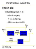
the outside pins. The picture below shows what a microcontroller looks like inside.
Physical configuration of the interior of a microcontroller
Thin lines which lead from the center towards the sides of the microcontroller
represent wires connecting inner blocks with the pins on the housing of the
microcontroller so called bonding lines. Chart on the following page represents the
center section of a microcontroller.
Microcontroller outline with its basic elements and internal connections
For a real application, a microcontroller alone is not enough. Beside a
microcontroller, we need a program that would be executed, and a few more
elements which make up a interface logic towards the elements of regulation (which
will be discussed in later chapters).
1.9 Program
Program writing is a special field of work with microcontrollers and is called
"programming". Try to write a small program in a language that we will make up
ourselves first and then would be understood by anyone.
START
REGISTER1=MEMORY LOCATION_A
REGISTER2=MEMORY LOCATION_B
PORTA=REGISTER1 + REGISTER2
END
The program adds the contents of two memory locations, and views their sum on
port A. The first line of the program stands for moving the contents of memory
location "A" into one of the registers of central processing unit. As we need the other
data as well, we will also move it into the other register of the central processing
unit. The next instruction instructs the central processing unit to add the contents of
those two registers and send a result to port A, so that sum of that addition would
be visible to the outside world. For a more complex problem, program that works on
its solution will be bigger.
Programming can be done in several languages such as Assembler, C and Basic
which are most commonly used languages. Assembler belongs to lower level
languages that are programmed slowly, but take up the least amount of space in
memory and gives the best results where the speed of program execution is
concerned. As it is the most commonly used language in programming
microcontrollers it will be discussed in a later chapter. Programs in C language are
easier to be written, easier to be understood, but are slower in executing from
assembler programs. Basic is the easiest one to learn, and its instructions are
nearest a man's way of reasoning, but like C programming language it is also slower
than assembler. In any case, before you make up your mind about one of these
languages you need to consider carefully the demands for execution speed, for the
size of memory and for the amount of time available for its assembly.
After the program is written, we would install the microcontroller into a device and
run it. In order to do this we need to add a few more external components necessary
for its work. First we must give life to a microcontroller by connecting it to a power
supply (power needed for operation of all electronic instruments) and oscillator
whose role is similar to the role that heart plays in a human body. Based on its
clocks microcontroller executes instructions of a program. As it receives supply
microcontroller will perform a small check up on itself, look up the beginning of the
program and start executing it. How the device will work depends on many
parameters, the most important of which is the skillfulness of the developer of
hardware, and on programmer's expertise in getting the maximum out of the device
with his program.