Formal Models of Operating System Kernels phần 2 pps
Bạn đang xem bản rút gọn của tài liệu. Xem và tải ngay bản đầy đủ của tài liệu tại đây (398.08 KB, 54 trang )
28 2 Standard and Generic Components
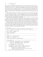
The hardware process is defined as:
HW = start.HW
1
HW
1
=(i
1
.saveregs + HW
1
+setregs.HW
1
+getregs.HW
1
+restoreregs.HW
1
) \ saveregs
The following pair of processes are intended to model the behaviour of
hardware when an interrupt occurs. The process Int
i
represents the ith in-
terrupt. When it receives its internal interrupt signal, i
i
, it signals that the
Interrupt Service Routine (ISR) corresponding to this interrupt should be ex-
ecuted; this is done by sending the
runisr
i
message. The interrupt process
then recurs, ready to accept another interrupt signal. The second process,
ISR
i
, is intended roughly to model the actions of the ISR corresponding to
interrupt i. When the ISR receives the signal to execute (runisr
i
), it performs
the service action and then instructs the hardware to restore the register set
to the way it was before the interrupt occurred. The ISR process then recurs,
so that it can accept another interrupt.
Int
i
= i
1
.runisr
1
.Int
i
ISR
i
= runisr.service.restoreregs.ISR
i
The hardware and interrupt subsystem can be thought of as the following
(parallel) composition of processes:
H = HW | Π
i∈I
(Int
i
| ISR
i
)
The next process models the interrupt mask. The interrupt mask deter-
mines whether interrupts are signalled or not (it is modelled in this book by
the Lock Object-Z class).
IntMask = on.IntMask(1)
IntMask(v)=off .IntMask(0)
+on.IntMask(1)
+stat.
istat(n).IntMask(n)
The interrupt mask enables the hardware model to be extended so that inter-
rupts can be enabled and disabled under programmer control. Integration of
the interrupt mask and the process P is left as an exercise for the interested
reader.
Themodelworksasfollows.Initially,theIntMask accepts an on event to
initialise the mask. Initialisation enables interrupts and takes the state of the
mask as its parameter (the value in parentheses). After this, the mask offers
three possible actions: off to disable interrupts, on to enable them and stat to
enquire about the state of the mask. When IntMask engages in an off action, it
disables interrupts (denoted by the 0 parameter). Alternatively, it can engage
in an on action. If interrupts are currently disabled, the on action re-enables
2.4 Hardware Model 29
them; otherwise, it does nothing. Finally, some other component (say, some
software) can enquire as to the state of the interrupt mask by engaging in
the third possible action, stat (status). The IntMask process then returns the
current status (denoted by n) via an
istat (interrupt status) action; enquiry
does not affect the state of the mask. This is indicated by the recursion on
the same value as that communicated by the
istat action.
This is a single-level interrupt scheme. Some processors have a multi-level
one. At the level of detail required in this book, the differences between single-
and multi-level interrupt schemes are not significant, so a single-level scheme
is assumed for simplicity.
Purely for interest, a multi-level interrupt mask, MLIMask, can be defined
as follows. First, the mask is initialised by participating in an allon (all on)
action:
MLIMask = allon.MLIMask(S )
Here, the parameter S denotes the set of all interrupt levels. The mask now
behavesasfollows:
MLIMask(S )=off (i).MLIMask(S \{i})
+on(i).MLIMask(S ∪{i})
+ison(i).
istat(i ∈ S ).MLIMask(S )
+offm(I ).MLIMask(S \ I )
+onm(I ).MLIMask(S ∪ I )
where I denotes a set of interrupt levels and i is an individual level.
2.4.2 Registers
The processor contains a set of general-purpose registersas well as a set of
more specialised ones: stack register, instruction pointer and status register
(sometimes called the “status word”). It is assumed that each register is one
PSU wide.
The model of the registers is rather minimal. There is not a lot that can
be proved about it.
It is assumed that the hardware is not a stack machine (i.e., a single-
address machine, that is). If a stack machine were the target, the registers
would not strictly be required. Actually, many stack machines do have the
odd off-stack register just as an optimisation.
The number of general-purpose registers is given by:
numregs : N
1
Note that no value is given. This is a partial specification (it is, in any case,
impossible to assign a value to numregs without knowing which processor is
being used).
The register names form the following set:
30 2 Standard and Generic Components
GENREG == {r
0
, ,r
numregs
−1
}
The contents of this set are of no further interest to us because the register
set will be manipulated as a complete entity.
The register set is defined as a function from register (index) to the value
it contains:
GENREGSET == GENREG → PSU
The status register contains a value. That value is of the following type.
It is assumed to be of the same size (in bits) as an element of PSU .
[STATUSWD]
This will be an enumeration, for example: overflow, division by zero, carry set.
The register state is defined by the following schema:
HWREGISTERS
hwregset : GENREGSET
hwstack : PSTACK
hwip : N
hwstatwd : STATUSWD
The general register set is hwregset,thestackisinhwstack, the instruction
pointer (program counter) is hwip and the status word is denoted by hwstatwd .
The following defines the zero elements for PSU and STATUSWD:
0
PSU
: PSU
clear : STATUSWD
The registers are initialised when the hardware starts up. This initialisation
is modelled by the following operation:
InitHWREGISTERS
HWREGISTERS
(∀ r : GENREGSET •
r ∈ hwregset
⇒ hwregset
(r)=0
PSU
)
hwip
=0
hwstack
= EmptyStack
hwstatwd
= clear
This schema does not appear in any of the kernels because it will have been
referenced (executed) before any kernel initialisation operations are executed.
It is included for completeness.
2.4 Hardware Model 31
2.4.3 Interrupt Flag
The interrupt flag is of crucial importance in the models that follow. The
flag is of a type containing two values (they could be true and false or 0 and
1—symbolic values are used instead for easier interpretation of often complex
schemata):
INTERRUPTSTATUS ::= inton | intoff
The value inton represents the hardware state in which interrupts are enabled.
The value intoff denotes the fact that interrupts have been disabled.
The interrupt flag itself is defined as:
INTERRUPTFLAG
iflag : INTERRUPTSTATUS
When the hardware starts up, it will execute an operation similar to that
denoted by the following schema:
InitINTERRUPTFLAG
INTERRUPTFLAG
iflag
= inton
This schema is similar to the register-initialisation schema. It is assumed that
the hardware executes it before the kernel bootstrap starts executing. This
will be the only time we see this schema.
There are three operations associated with the interrupt flag. Two are
under program control: one disables and one enables interrupts. The remaining
operation raises the interrupt and performs operations such as saving the
current register state and transferring control to an ISR.
Theoperationtodisableinterruptsismodelledhereas:
DisableInterrupts
∆INTERRUPTFLAG
iflag
= intoff
The operation to enable interrupts is:
EnableInterrupts
∆INTERRUPTFLAG
iflag
= inton
Interrupts are disabled and then enabled again to ensure that no interrupts
occur during the execution of a piece of code. They are used as a kind of low-
level mutual exclusion mechanism.
32 2 Standard and Generic Components
It is usual to define a couple of operations, named Lock and Unlock,to
perform the disabling and enabling of interrupts. These operations are usually
defined as assembly language macros. The names are used because they are
better mnemonics. They are defined as:
Lock = DisableInterrupts
and:
Unlock = EnableInterrupts
2.4.4 Timer Interrupts
Most processors have a hardware clock that generates interrupts at a regular
rate (e.g., typically 60Hz, the US mains supply frequency). Timer interrupts
are used to implement process alarms (sleep periods—the term “alarm” is used
in this book by analogy with “alarm clock”). A process suspends itself for a
specified period of time. When that time, as measured by the hardware clock,
has expired, the process is resumed (by giving it an “alarm call”). A piece
of code, which will be called the clock driver in this book, is responsible for
(among other things) suspending processes requesting alarms and for resuming
them when the timer has expired.
This subsection is concerned with the general operation of the clock driver
and with clock interrupts. The clock will be used in a number of places in the
kernels that follow and it will be re-modelled in various forms. The purpose
of the current section is just to orient the reader and to show that such a
low-level model can be produced in Z (later in Object-Z) in a fashion that is
relatively clear and, what is more, in a form that allows a number of properties
to be proved.
The hardware clock is associated with the interrupt number:
clockintno : INTNO
Time is modelled as a subset of the naturals:
TIMEVAL == N
Here, time is expressed in terms of uninterpreted units called “ticks” (assumed
to occur at regular intervals, say every 1/60 second).
The clock is just a register that contains the current time, expressed in
some units:
CLOCK
timenow : TIMEVAL
The hardware initialises the clock on startup. (The clock can also be reset
on some processors.)
2.4 Hardware Model 33
InitCLOCK
CLOCK
timenow
=0
The length of the clock tick often needs to be converted into some other
unit. For example, a 60Hz “tick” might be converted into seconds.
ticklength : TIMEVAL
The clock updates itself on every hardware “tick”:
UpdateCLOCKOnTick
∆CLOCK
timenow
= timenow + ticklength
When the current time is required, the following operation is used:
TimeNow
ΞCLOCK
now!:TIMEVAL
now!=timenow
When a process needs to set an alarm, it sends the clock driver a message
of the following type:
TIMERRQ == PREF × TIMEVAL
The message contains the identifier of the requesting process (here, of type
PREF , the most general process reference type) plus the time by which it
expects to receive the alarm.
The following axioms define functions to access elements of TIMERRQ
(which are obvious and merit no comment):
timerrq pid : TIMERRQ → PREF
timerrq time : TIMERRQ → TIMEVAL
∀ t : TIMERRQ •
timerrq pid(t)=fst t
timerrq time(t)=snd t
The queue is represented as a finite set of requests. An instance of
QUEUE[X ] could be used but, as will be seen, searching might have to be
performed to find the process to wake and the actual arrival time of requests
in the queue is not of any particular importance, so a more abstract view of
the queue, as a collection, is used instead.
34 2 Standard and Generic Components
The request queue is defined as:
TIMERRQQUEUE
telts : F TIMERRQ
The request queue is initialised by the following operation. It can be called
at any time the kernel is running, say on a warm reboot.
InitTIMERRQQUEUE
TIMERRQQUEUE
telts
= ∅
The following schema defines a predicate that is true when the request
queueisempty:
EmptyTIMERRQQUEUE
ΞTIMERRQQUEUE
telts = ∅
The following three schemata define operations that add and remove re-
quests:
EnqueueTIMERRQ
∆TIMERRQQUEUE
tr?:TIMERRQ
telts
= telts ∪{tr?}
RemoveFirstTIMERRQ
∆TIMERRQQUEUE
tr!:TIMERRQ
{tr!}∪telts
= telts
This operation removes the first element of the queue. It is a non-deterministic
operation.
RemoveTIMERRQQueueElt
∆TIMERRQQUEUE
tr?:TIMERRQ
tr? ∈ telts
telts
= telts \{tr?}
2.4 Hardware Model 35
This schema defines an operation that removes an arbitrary element of the
request queue.
The following schema defines a combination of a clock and a request queue.
The instance of CLOCK is intended to be a register holding a copy of the
hardware clock’s current value. The idea is that the clock driver copies the
hardware clock’s value so that the driver can refer to it without needing to
access the hardware.
TIMER = TIMERRQQUEUE ∧ CLOCK
This expands into:
telts : F TIMERRQ
timenow : TIMEVAL
The timer is initialised by the obvious operation:
TIMERInit =
InitCLOCK ∧
TIMERInit
This expands into:
TIMER
CLOCK
timenow
=0
telts
= ∅
The following condition must always hold:
Proposition 11. At any time, now:
∀ tr : TIMERRQ •
tr ∈ telts ⇒ timerrq
time(tr) > now
Proposition 12. At any time, now:
¬∃tr : TIMERRQ •
tr ∈ telts ∧ timerrq
time(tr) ≤ now
Both of these propositions are consequences of Proposition 92 (p. 173).
Their proofs are omitted.
In order to unblock those processes whose alarms have gone off, the follow-
ing schema is used. It returns a set of requests whose time component specifies
atimethatisnowinthepast:
36 2 Standard and Generic Components
TimerRequestsNowActive
∆TIMER
trqset!:F TIMERRQ
trqset!={trq : TIMERRQ | trq ∈ telts ∧ timerrq time(trq) ≤ timenow • trq}
telts
= telts \ trqset!
This is the basis of a CLOCK process:
OnTimerInterrupt =
(UpdateCLOCKOnTick
o
9
((TimerRequestsNowActive[trqset/trqset!] ∧
(∀ trq : TIMERRQ | trq ∈ trqset ∧ timerrq
pid(trq) ∈ known procs •
(∃ p : PREF; | p = timerrq
pid(trq) •
MakeReadypq[p/pid?])))
\ {trqset}))
The operation works as follows. First, the clock is updated by one tick. Then,
those processes whose alarms have gone off (expired) are found in and removed
from the set of waiting processes. Each one of these processes is put into the
ready queue (MakeReadypq[p/pid?]).
The basic operation executed by a process when requesting an alarm is
the following:
WaitForTimerInterrupt
=
(([CURRENTPROCESS; time?:TIMEVAL; trq : TIMERRQ |
trq =(currentp, time?)] ∧
Lock ∧ EnqueueTIMERRQ[trq/tr?])
\ {trq}∧
MakeUnready[currentp/pid?] ∧
SwitchFullContextOut[currentp/pid?] ∧
SCHEDULENEXT )
o
9
Unlock
In Chapter 4, some properties of the clock process and its alarm mechanism
will be proved.
2.4.5 Process Time Quanta
In some of the kernels to follow, user processes are scheduled using a pre-
emptive method. Pre-emption is implemented in part using time quanta. Each
user process (system processes are not allocated time quanta and cannot be
pre-empted) is allocated a time quantum, a value of type TIMEVAL.On
each hardware clock “tick”, the time quantum is decremented. When the
quantum reaches some threshold value, the process is suspended. When that
same process is executed the next time, it is assigned a new quantum.
To begin, the type of time
quantum is defined:
time quantum : TIMEVAL
2.4 Hardware Model 37
For the purpose of this book, every user process uses the same values for
initialisation and threshold.
The following schema retrieves the value of a process’ time quantum from
the process table.
ProcessQuantum
ΞPROCESSES
pid?:PREF
timeq!:TIMEVAL
timeq!=pquants(pid?)
The next schema defines an operation that sets the initial value for its
time quantum:
SetInitialProcessQuantum
∆PROCESSES
pid?:PREF
time quant?:TIMEVAL
pquants
= pquants ∪{pid? → time quant?}
When a process’ time quantum is to be reset, the following operation does
the work:
ResetProcessTimeQuantum =
(∃ q : TIMEVAL | q = time
quantum •
UpdateProcessQuantum[time
quantum/timeq?])
The following schema models an operation that sets the current value of
its time quantum in its process descriptor:
UpdateProcessQuantum
∆PROCESSES
pid?:PREF
timeq?:TIMEVAL
pquants
= pquants ⊕{pid? → timeq?}
This operation can be used when the process is interrupted or when a higher-
priority process must be scheduled.
There is a storage location that holds the current process’ time quantum
while it executes:
SetCurrentProcessQuantum
∆CURRENTPROCESSpq
timequant?:TIMEVAL
tq
= timequant?
38 2 Standard and Generic Components
The quantum is updated by:
UpdateCurrentProcessQuantum
∆CURRENTPROCESSpq
now?:TIMEVAL
tq
= tq − now?
This schema defines a predicate that is satisfied when the current process’
time quantum has expired:
CurrentProcessQuantumHasExpired
ΞCURRENTPROCESSpq
tq ≤ 0
The current process quantum is read from the storage location by the next
schema:
CurrentProcessQuantum
ΞCURRENTPROCESSpq
tquant!:TIMEVAL
tquant!=tq
On each hardware clock tick, the current process’ time quantum is updated
by the following operation:
UpdateCurrentQuantumOnTimerClick =
(TimeNow[now/now !] ∧
UpdateCurrentProcessQuantum[now/now?])
\ {now}
This operation is already represented in the last line of OnTimerInterrupt.
When a process is blocked, the following are required:
SaveCurrentProcessQuantum =
(CurrentProcessQuantum[tquant/tquant!] ∧
UpdateProcessQuantum[tquant/timeq?])
\ {tquant}
This expands into:
ΞCURRENTPROCESSpq
∆PROCESSES
(∃ tquant : TIMEVAL •
tquant = tq ∧
pquants
= pquants ⊕{pid? → tquant?})
2.5 Processes and the Process Table 39
On each clock tick, the CLOCK process executes the following operation:
SuspendOnExhaustedQuantum =
(CurrentProcessQuantumHasExpired ∧
ResetProcessTimeQuantum ∧
(SuspendCurrent
o
9
SCHEDULENEXTn))
∨ (UpdateCurrentProcessQuantum ∧
ContinueCurrent)
SetNewCurrentProcessQuantum
=
(ProcessQuantum[tquant/timeq!] ∧
SetCurrentProcessQuantum[tquant/timequant?])
\ {tquant}
This expands into:
ΞPROCESSES
∆CURRENTPROCESSpq
pid?:PREF
(∃ tquant : TIMEVAL •
tquant = pquants(pid?) ∧
tq
= tquant)
It simplifies to tq
= pquants(pid?).
2.5 Processes and the Process Table
This section deals with a representation of processes and the process table.
Each process is represented by an entry in the process table; the entry is a
process descriptor. The process descriptor contains a large amount of infor-
mation about the state of the process it represents; the actual contents of the
process descriptor depend upon the kernel, its design and its purpose (e.g.,
a real-time kernel might contain more information about priorities and time
than one for an interactive system as well as the hardware).
The purpose of this section is not to define the canonical process descriptor
and process table for the kernels in this book (which, in any case, differ among
themselves), nor to define the canonical structure for the process table (the one
here is somewhat different from those that follow). Instead, it is intended as a
general definition of these structures and as a place where general properties
can be identified and proved.
As will become clear from the kernel models that follow, the process table
in this section differs somewhat from the others in this book. In particular, the
process table here is modelled as a collection of mappings, while the others
are more obviously “tables”. The reasons for this difference are many. The
most important, for present purposes, are:
40 2 Standard and Generic Components
• The current model is at a higher level than the others.
• The current model separates the different attributes of the process descrip-
tor into individual mappings.
Some kernels (e.g., some versions of Unix) use the representation used here.
The representation of this section has a slight advantage over the standard
table representation: for fast real time, it is possible to access components of
the process descriptor simultaneously—this might also be of utility in a kernel
running on a multi-processor system.
The section begins with a set of definitions required to support the defini-
tion of the process descriptor and the process table.
In particular, there is a limit to the number of processes that can be
present in the system. There is one process descriptor for each process, so this
represents the size of the process table.
maxprocs : N
1
A type for referring to processes must be defined:
PREF == 0 maxprocs
The null and idle processes must be defined:
IdleProcRef : PREF
NullProcRef : PREF
NullProcRef =0
IdleProcRef = maxprocs
where NullProcRef is the “name” of no process and IdleProcRef is the “name”
of the idle process.
It is possible to define a set of “real” process names, that is process iden-
tifiers that represent actual processes. An “actual” process can be defined as
a process associated with code that does something useful. The null process
has no code. The idle process consists of a empty infinite loop.
Given this definition, the set, REALPROCS can be defined as:
REALPROCS == PREF \{NullProcRef , IdleProcRef }
That is, REALPROCS == 1 (maxprocs − 1). Another, but less useful, set
of identifiers can also be defined:
IREALPROCS == PREF \{NullProcRef }
Writing out the definitions, this is IREALPROCS == 1 maxprocs. These
additional types will not be used in this specification but might be of some
use in refinement.
Hardware devices are assigned an identifying number:
2.5 Processes and the Process Table 41
DEVICEID == N
Each process has a state in addition to that denoted by the PSW.
PROCSTATUS ::= pstnew
|
pstrunning
| pstready
| pstwaiting
|
pstswappedout
| pstzombie
| pstterm
Processes come in three kinds:
PROCESSKIND ::= ptsysproc
| ptuserproc
| ptdevproc
These kinds are system, user and device processes.
The code and data areas of a process’ main-store image need to be repre-
sented:
[PCODE, PDATA]
For the time being, we can ignore PCODE and PDATA. Their elements are
structured in a way that will only be relevant during refinement; similarly, the
PSTACK type also has elements whose structures can, for the most part, be
ignored. (The structure of elements of type PSTACK is only really of relevance
to interrupt service routines and the mechanisms that invoke them—typically
they push a subset of the current register set onto the stack.)
The process descriptor (sometimes called the process record) is defined
by the following schema; together all process descriptors in the system form
the process table. It is the primary data structure for recording important
information about processes. The information includes a representation of
the process’ state, which is retained while the process is not executing. On
a context switch, the state (primarily, hardware registers, IP and stack) is
copied into the process descriptor for storage until the process is next ex-
ecuted. When next selected to run, the state is copied back into registers.
The process descriptor does hold other information about the process: data
about the storage areas it occupies, message queues, priority information and
a symbolic representation of its current state (in this book, an element of type
PROCSTATUS).
In this chapter, process descriptors are represented as sets of mappings
from process identifiers to the various attribute types. This representation
finds a natural representation as a collection of arrays. An alternative that
is commonly encountered in working systems, is to collect the information
42 2 Standard and Generic Components
about each process into a record or structure; all process descriptors are then
implemented as an array of these records. The record implementation has the
advantage that all relevant information about a process is held in one data
structure. The main disadvantage is that the record has to be accessed as an
entity. In the array-based implementation (the one adopted in this chapter,
i.e.), individual components are accessed separately. The advantage to the
separate-access approach is seen when locking is considered: when one com-
ponent array is being accessed under a lock, the others remain available to be
locked.
In this representation, the process table is implicitly defined as the map-
ping from process reference (PREF ) to attribute value:
PROCESSES
pstatus : PREF → PROCSTATUS
pkinds : PREF → PROCESSKIND
pprios : PREF → PRIO
pregs : PREF → GENREGSET
pstacks : PREF → PSTACK
pstatwds : PREF → STATUSWD
pcode : PREF → PCODE
pdata : PREF → PDATA
pips : PREF → N
known procs : F PREF
NullProcRef ∈ known procs
known procs = dom pstatus
dom pstatus = dom pkinds
dom pkinds = dom pprios
dom pprios = dom pregs
dom pregs = dom pstacks
dom pstacks = dom pstackwds
dom pstackwds = dom pcode
dom pcode = dom pdata
dom pdata = dom pips
known uids = ran pips
The conjunct, NullProcRef , is added to the predicate because it is required
that NullProcRef actually refer to the null process. It should never be the
case that the null process appears in the process table.
It is possible to exclude IdleProcRef from the process table in a manner
identical to NullProcRef . In the case of IdleProcRef , matters are less clear.
The idle process is a real process: it has code but probably no data or stack
areas. It is quite possible to have an idle process without representing it in
the process table. The idle process is only executed whenever the ready queue
is empty, so a small piece of code can do all the necessary work. To some,
this will appear an ad hoc solution; to others, it will appear totally natural.
2.5 Processes and the Process Table 43
At the moment, the idle process will be represented in the process table, even
though it requires an additional slot (this is, after all, a specification, not an
implementation).
When refinement is performed, the inclusion of IdleProcRef and the ex-
clusion of NullProcRef are of some importance. They determine the range of
possible values for the domains of the components of process descriptors. In
other words, their inclusion and exclusion determine what a “real process”
can be; this is reflected in the type to which PREF refines: REALPROCS
or IREALPROCS. (A hidden goal of the refinement process is to represent
NullProcRef as, for example, a null pointer.)
Proposition 13. NullProcRef does not refer to a “real” process.
Definition 1 . A “real” process must be interpreted as one that has code and
other attributes (stack, data, status, instruction pointer and so on). Alterna-
tively, a “real” process is one that can be allocated either by the kernel or as
a user process.
More technically, a “real” process is one whose parameters are represented
in the process table and, hence, whose identifier is an element of known
procs.
Note that this definition is neutral with respect to the idle process. Some
systems might regard it as “real” and include an operation to create the idle
process. Other systems, MINIX [30] for example, regard the idle process as
a pseudo-process that is implemented as just a piece of kernel code that is
executed when there is nothing else to do; as in other systems built using
this assumption, the idle process is not represented by an entry in the process
table.
The above definition could be extended to include the idle process, of
course.
Proof. The components of the process description, pstate, pkind, pstack,
pregs, etc., all have identical domains by the first part of the invariant of
PROCESSES.Thatis:
dom pstatus = dom pkind ∧
dom pkinds = dom pprios ∧
dom pprios = dom pregs ∧
dom pregs = dom pstacks ∧
dom pstacks = dom pips ∧
dom pcode = dom pstacks ∧
dom pdata = dom pcode ∧
dom pips = dom pstatus
Furthermore, the domains are all identical to known procs since dom pstatus =
known
procs.SinceNullProcRef ∈ known procs, it follows that NullProcRef ∈
dom pregs (for example). By Definition 1, the null process is not a “real” pro-
cess. ✷
44 2 Standard and Generic Components
The process table is initialised by the following operation:
InitPROCESSES
PROCESSES
known procs
= ∅
A process is removed from the process table by the operation modelled by
the following schema:
DelProcess
∆PROCESSES
pid?:PREF
pstatus
= {pid?}
−
pstatus
pkinds
= {pid?}
−
pkinds
pprios
= {pid?}
−
pprios
pregs
= {pid?}
−
pregs
pstacks
= {pid?}
−
pstacks
pips
= {pid?}
−
pips
or, more simply: pid? ∈ known procs
.
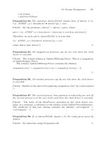
Proposition 14. DelProcess[p/pid?] implies that p ∈ known prcs
.
Proof. Since all domains are identical, take, for example, the case of pregs:
pregs
= {p}
−
pregs
Taking domains and using the identity dom pregs = known
procs:
dom pregs
= known
procs
= dom({p}
−
pregs)
= dom(pregs \{p})
Therefore, p ∈ known
procs
.
The same reasoning can be applied to all similar functions in PROCESSES. ✷
A process is added to the process table by the AddProcess operation:
AddProcess
∆PROCESSES
pid?:PREF
knd?:PROCESSKIND
status?:PROCSTATUS
stat?:STATUSWD
regs ?:GENREGSET
2.5 Processes and the Process Table 45
stk?:PSTACK
prio?:PRIO
ip?:N
pstatus
= pstatus ∪{pid? → status?}
pkinds
= pkinds ∪{pid? → knd?}
pprios
= pprios ∪{pid? → prio?}
pregs
= pregs ∪{pid? → regs ?}
pstatwds
= pstatwds ∪{pid? → stat?}
pips
= pips ∪{pid? → ip?}
pstacks
= pstacks ∪{pid? → stk?}
Proposition 15. (AddProcess[p/pid?, ]
o
9
DelProcess[p/pid?]) is the iden-
tity on the process table.
Proof. This proposition states that the effect of adding a process and im-
mediately deleting it leaves the process table invariant.
Since PROCESSES is rather large, only a part will be considered in detail.
The composition can be written as:
∃ pstacks
: PREF → PSTACK •
pstacks
= pstacks ∪{p? → stk}∧
pstacks
= {p?}
−
pstacks
which simplifies to:
pstacks
= {p?}
−
(pstacks ∪{p? → stk})
So:
dom({p?}
−
(pstacks ∪{p? → stk}))
= (dom pstacks ∪ dom{p? → stk}) \{p?}
= ((dom pstacks) ∪{p?}) \{p?}
Therefore:
dom pstacks
= dom(pstacks ∪{p?}) \{p?}
= dom pstacks
✷
The priority of a process is returned by the following operation:
ProcessPriority
ΞPROCESSES
pid?:PREF
prio!:PRIO
prio!=pprios(pid?)
46 2 Standard and Generic Components
The kind of process is returned by:
KindOfProcess
ΞPROCESSES
pid?:PREF
knd!:PROCESSKIND
knd!=pkinds(pid?)
A process’ current status is retrieved from the process table by the follow-
ing operation:
StatusOfProcess
PROCESSES
pid?:PREF
ps!:PROCSTATUS
ps!=pstatus(pid?)
InitialiseProcessStatus
∆PROCESSES
pid?:PREF
pstat?:PROCSTATUS
pstatus
= pstatus ∪{pid? → pstat?}
Process status changes frequently during its execution. The following op-
eration alters the status:
UpdateProcessStatus
∆PROCESSES
pid?:PREF
pstat?:PROCSTATUS
pstatus
= pstatus ⊕{pid? → pstat}
The following operations set the process status to designated values as and
when required:
SetProcessStatusToNew =
([pstat : PROCSTATUS | pstat = pstnew] ∧
UpdateProcessStatus[pstat/pstat?])
\ {pstat}
This operation is called when a process has been created but not added to
the ready queue.
When a process enters the ready queue, the following operation changes
its status to reflect the fact:
2.5 Processes and the Process Table 47
SetProcessStatusToReady
=
([pstat : PROCSTATUS | pstat = pstready] ∧
UpdateProcessStatus[pstat/pstat?])
\ {pstat}
The SetProcessStatusToRunning operation should be called when a pro-
cess begins execution:
SetProcessStatusToRunning =
([pstat : PROCSTATUS | pstat = pstrunning] ∧
UpdateProcessStatus[pstat/pstat?])
\ {pstat}
When a process is suspended for whatever reason, the following operation
is called to set its status to pstwaiting:
SetProcessStatusToWaiting =
([pstat : PROCSTATUS | pstat = pstwaiting] ∧
UpdateProcessStatus[pstat/pstat?])
\ {pstat}
In the second kernel below (Chapter 4), processes can be swapped out to
disk space. The status of such a process is set by the following schema. As
with all of these schemata, the variable pstat represents the new state.
SetProcessStatusToZombie =
([pstat : PROCSTATUS | pstat = pstzombie] ∧
UpdateProcessStatus[pstat/pstat?])
\ {pstat}
This schema is used when a process terminates but has not yet released
its resources:
SetProcessStatusToTerminated =
([pstat : PROCSTATUS | pstat = pstterm] ∧
UpdateProcessStatus[pstat/pstat?])
\ {pstat}
For many purposes, it is necessary to know whether a given process ref-
erence denotes a process that is in the process table. The following schema
defines that test:
KnownProcess
ΞPROCESSES
pid?:PREF
pid? ∈ known procs
It is not possible to allocate processes indefinitely. The following operation
determines whether new processes can be allocated.
CanAllocateProcess
PROCESSES
known procs ⊂ PREF
48 2 Standard and Generic Components
The identifier of the next new process is generated by the following (rela-
tively abstract) schema.
NextPREF
PROCESSES
pid!:PREF
(∃ p : PREF | p ∈ (PREF \ known procs) •
p = NullProcRef ∧ p = IdleProcRef ∧
pid!=p)
or:
pid! ∈{p : PREF • p ∈ known procs}
The way names are allocated to new processes is as follows. There is a set
of all possible process references, PREF . If a process’ identifier is not in
known
procs, the set of known processes (i.e., the names of all processes
that are currently in the system—the domain of all attribute mappings), it
can be allocated. Allocation is, here, the addition of a process reference to
known
procs.
If all processes have been allocated, the following schema’s predicate is
satisfied.
ProcessesFullyAllocated
PROCESSES
known procs = PREF \{NullProcRef , IdleProcRef }
Note that neither IdleProcRef,norNullProcRef represent real processes that
can be allocated and deallocated in the usual way. Indeed, IdleProcRef denotes
the idle process that runs whenever there is nothing else to do; it is already
defined within the kernel. The constant NullProcRef denotes the null process
and is only used for initialisation or in cases of error.
The following is just a useful synonym:
CannotAllocateProcess = ProcessesFullyAllocated
Proposition 16. For any process, p, such that p ∈ known
procs:
DelProcess ⇒¬ProcessesFullyAllocated
Proof. By Proposition 14, the operation DelProcess applied to a process,
p, implies that p ∈ known
procs
.
Note, first of all, that p cannot be one of NullProcRef or IdleProcRef.
The definition of CanAllocatePREF is known
procs ⊂ PREF ,whichim-
plies that there is some subset S : F PREF s.t., known
procs ∪ S = PREF;
(strictly speaking:
2.5 Processes and the Process Table 49
known procs ∪ S = PREF \{NullProcRef , IdleProcRef }
so CanAllocatePREF implies that if S = ∅,thenp ∈ S will be the next
PREF to be allocated, so known
procs ∪{p}∪(S \{p})=PREF .IfS = ∅,
clearly known
procs = PREF . Therefore PREF \ S = known procs.
In the case of deletion, known
procs
= known procs \{p?},so:
known procs
= known procs \{p}
=(PREF \ S) ∪{p}
= PREF \ (S ∪{p})
For PREF = known procs,itisimpossiblethatp ∈ S. Therefore, it can be
concluded that the predicate of ¬ ProcessesFullyAllocated
does not hold. ✷
It might be useful to know whether there are any processes in the system.
The following schema provides that ability:
NoProcessesInSystem
ΞPROCESSES
known procs = ∅
Proposition 17. AddProcess ⇒ pid ∈ known procs
.
Proof. For AddProcess, consider the case pstacks
= pstacks ∪{p? → stk}.
Since dom pstacks = known
procs and dom pstacks
= known procs
, it fol-
lows that: dom pstacks = known
procs and:
dom pstacs = dom(pstacks ∪{p? → stk})
= (dom pstacks) ∪ (dom{p? → stk})
= dom pstacks ∪{p?}
= known
procs
✷
Proposition 18.
¬ NoProcessesInSystem ∧ (NextPREF ∧ AddProcess)
n
∧ 0 < n ≤ maxprocs ⇒
¬ ProcessesFullyAllocated
Proof. The proposition statement expands to:
known procs = ∅ ∧
(NextPref ∧ AddProcess)
n
∧
0 < n ≤ maxprocs
50 2 Standard and Generic Components
It has already been established (Proposition 17) that
AddProcess[p/pid?, ] ⇒ p ∈ known
procs
(2.1)
so:
(NextPref [p/pid!] ∧ AddProcess[p/pid?]) ⇒ p ∈ known procs
Writing the available identifiers as:
A =(PREF \{NullProcRef , IdleProcRef }) \ known
procs
We write A for the set of available identifiers before NextPREF ∧ AddProcess and
A
for that afterwards. Then #A is the cardinality of A, and so #A
=#A −1. This
is justified by:
A
=(PREF \{NullProcRef , IdleProcRef }) \ known procs
=(PREF \{NullProcRef , IdleProcRef }) \ (known procs ∪{p})
where p is the newly allocated identifier.
Consequently, for (NextPREF [p
m
] ∧ AddProcess[p
m
/pid?, ])
m
and for some
m, 0 < m < maxprocs − 1
A
=(PREF \{NullProcRef , IdleProcRef }) \ known procs
=(PREF \{NullProcRef , IdleProcRef }) \ (known
procs ∪{p
1
, ,p
m−1
})
Therefore, for m = maxprocs,
A
=(PREF \{NullProcRef , IdleProcRef }) \ known procs
=(PREF \{NullProcRef , IdleProcRef }) \ known
procs ∪{p
1
, ,p
m
}
Since the interval 1 maxprocs contains exactly m elements:
(PREF \{NullProcRef , IdleProcRef }) \ known
procs
= ∅
✷
It should be noted that if the idle process is not regarded as a “real” process,
the statement of the proposition should be restricted to ∧ 0 < n < maxprocs.
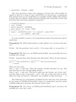
Proposition 19. The operations AddProcess and DelProcess are inverse op-
erations. That is, for any p, AddProcess[p/pid?]
o
9
DelProcess[p/pid?] implies
that #known
procs =#known procs
.
Proof. This follows immediately by induction from Proposition 15. ✷
2.6 Context Switch 51
2.6 Context Switch
Context switches occur when a process is swapped on or off the processor.
This section outlines a scheme for modelling context switching.
Basically, a context switch involves the transfer of hardware and other state
information from or to the process descriptor. Of the registers, the most impor-
tant is the instruction pointer. Context switches are expensive because they
copy the contents of all hardware registers into the current process descrip-
tor. They occur when the scheduler determines that another process should
be allocated to the processor. They are also required for the specification of
semaphores.
There are two main operations involved in context switching: one to copy
state data from the process descriptor to the hardware and one to copy data
in the opposite direction. The schemata defined in this section are included as
an illustration. They will be redefined with slight variations when required.
The SaveAllHWRegisters operation copies the contents of the registers
used by a process into its process descriptor. The operation is complemented
by RestoreAllHWRegisters, which reads the process descriptor and copies
items from it to the hardware’s general-purpose registers. In the represen-
tation below, the instruction pointer is the last register to be set from the
process descriptor.
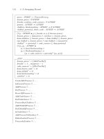
SaveAllHWRegisters
∆PROCESSES
HWREGISTERS
pid?:PREF
(∀ r : GENREG •
pregs
(pid?)(r)=hwregset(r))
pstacks
(pid?) = hwstack
pstatwds
(pid?) = hwstatwd
pips
(pid?) = hwip
SwitchContextOut = SaveAllHWRegisters
RestoreAllHWRegisters
PROCESSES
HWREGISTERS
pid?:PREF
hwstack
= pstacks(pid?)
hwstatwd
= pstatwds(pid?)
hwip
= pips(pid?)
(∀ r : GENREG •
hwregset
(r)=pregs(pid?)(r ))
52 2 Standard and Generic Components
SwitchContextIn
= RestoreAllHWRegisters
Sometimes, for example when an interrupt occurs, a partial context switch
can occur. Partial context switches only save part of the data normally
switched by a context switch. Although the detailed workings of the hard-
ware interrupt subsystem are mostly ignored in this book, it is interesting,
just as an orienting exercise, to include the following schemata.
A partial context switch is described by the following two schemata:
SaveHWGeneralRegisters
∆PROCESSES
HWREGISTERS
pid?:PREF
(∀ r : GENREG •
pregs
(pid?)(r)=hwregset(r))
SavePartialContext
= SaveHWGeneralRegisters
RestoreHWGeneralRegisters
∆PROCESSES
ΞHWREGISTERS
pid?:PREF
∀ r : GENREG •
hwregset(r)=pregs
(pid?)(r)
RestorePartialContext
= RestoreHWGeneralRegisters
2.7 Current Process and Ready Queue
This section presents a simple model of the operation of the kernel’s scheduler.
It uses a simple FIFO queue to hold the processes that are ready to execute;
this is readyq. The identifier of the process currently executing is stored in
currentp.
CURRENTPROCESS
currentp : PREF
readyq : ProcQueue
Here, ProcQueue can either be regarded as an instantiation of the generic
QUEUE type or of a new type.


