Thiết kế và thực hiện hệ thống VLSI - 02 pot
Bạn đang xem bản rút gọn của tài liệu. Xem và tải ngay bản đầy đủ của tài liệu tại đây (730.08 KB, 35 trang )
Design and Implementation of
VLSI Systems
Lecture 02
Thuan Nguyen
Faculty of Electronics and Telecommunications,
University of Science, VNU HCMUS
Spring 2011
1
LECTURE 2: CMOS CIRCUIT
2
MOS Transistor
1
CMOS Logic
2
LECTURE 2: CMOS CIRCUIT
3
MOS Transistor
1
CMOS Logic
2
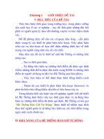
IMPACT OF DOPING ON
SILICON RESISTIVITY
dope with
phosphorous
or arsenic
n-type
dope with
boron
p-type
silicon
4.99510
22
atoms in cm
3
Resistivity 3.2 10
5
Ωcm
1 atom in billion 88.6 Ωcm
1 atom in million 0.114 Ωcm
1 atom in thousand 0.00174 Ωcm
1 atom in billion 266.14 Ωcm
1 atom in million 0.344 Ωcm
1 atom in thousand 0.00233 Ωcm
Electrons are more mobile/faster than holes
MOS TRANSISTOR
4
WHAT HAPPENS IF WE SANDWICH P & N TYPES?
n
p
A
B
Al
One-dimensional
representation
In equilibrium, the drift and diffusion components of current
are balanced; therefore the net current flowing across the
junction is zero.
5
WHAT HAPPENS IF WE SANDWICH P & N TYPES?
6
PN-JUNCTION REGIONS OF OPERATION
In reverse bias, the width
of the depletion region
increases. The diode acts
as voltage-controlled
capacitor.
A forward bias
decreases the potential
drop across the
junction. As a result,
the magnitude of the
electric field decreases
and the width of the
depletion region
narrows.
7
NMOS AND PMOS TRANSISTORS
nMOS transistor
pMOS transistor
Each transistor consists of a stack of a conducting gate, an insulating
layer of silicon dioxide and a semiconductor substrate (body or bulk)
Body is typically grounded Body is typically at supply voltage
8
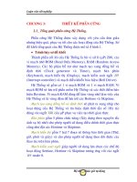
NMOS TRANSISTOR
n+
p
GateSource Drain
bulk Si
SiO
2
Polysilicon
n+
g=0: When the gate is at a low voltage (V
GS
< V
TN
):
p-type body is at low voltage
source and drain-junctions diodes are OFF
transistor is OFF, no current flows
g=1: When the gate is at a high voltage (V
GS
≥ V
TN
):
negative charge attracted to body
inverts a channel under gate to n-type
transistor ON, current flows, transistor
can be viewed as a resistor
9
NMOS PASS ‘0’ MORE STRONGLY THAN ‘1’
n+
p
GateSource Drain
bulk Si
SiO
2
Polysilicon
n+
• Why does ‘1’ pass degraded?
10
PMOS TRANSISTOR
SiO
2
n
GateSource Drain
bulk Si
Polysilicon
p+ p+
g=0: When the gate is at a low voltage (V
GS
< V
TP
):
positive charge attracted to body
inverts a channel under gate to p-type
transistor ON, current flows
g=1: When the gate is at a high voltage (V
GS
≥ V
TP
):
negative charge attracted to body
source and drain junctions are OFF
transistor OFF, no current flows
11
PMOS PASS ‘1’ MORE STRONGLY THAN ‘0’
SiO
2
n
GateSource Drain
bulk Si
Polysilicon
p+ p+
• Why does ‘0’ pass degraded?
12
LECTURE 2: CMOS CIRCUIT
13
MOS Transistor
1
CMOS Logic
2
pMOS + nMOS = CMOS
CMOS LOGIC
14
V
DD
A Y
GND
A Y
An nMOS and pMOS make up an inverter
MORE CMOS GATES
What is this gate function?
15
A
B
Y
3-INPUT NANDS
What are the advantages of CMOS circuit style?
16
pMOS
pull-up
network
output
inputs
nMOS
pull-down
network
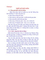
SERIES-PARALLEL COMBINATIONS
17
nMOS: 1 = ON
pMOS: 0 = ON
Series: both must be ON
Parallel: either can be ON
(a)
a
b
a
b
g1
g2
0
0
a
b
0
1
a
b
1
0
a
b
1
1
OFF OFF OFF ON
(b)
a
b
a
b
g1
g2
0
0
a
b
0
1
a
b
1
0
a
b
1
1
ON OFF OFF OFF
(c)
a
b
a
b
g1 g2
0
0
OFF ON ON ON
(d) ON ON ON OFF
a
b
0
a
b
1
a
b
11 0 1
a
b
0
0
a
b
0
a
b
1
a
b
11 0 1
a
b
g1 g2
WHAT ARE THE TRANSISTOR SCHEMATICS OF
THE NOR GATE?
2:00 1:59 1:58 1:57 1:56 1:55 1:54 1:53 1:52 1:51 1:50 1:49 1:48 1:47 1:46 1:45 1:44 1:43 1:42 1:41 1:40 1:39 1:38 1:37 1:36 1:35 1:34 1:33 1:32 1:31 1:30 1:29 1:28 1:27 1:26 1:25 1:24 1:23 1:22 1:21 1:20 1:19 1:18 1:17 1:16 1:15 1:14 1:13 1:12 1:11 1:10 1:09 1:08 1:07 1:06 1:05 1:04 1:03 1:02 1:01 1:00 0:59 0:58 0:57 0:56 0:55 0:54 0:53 0:52 0:51 0:50 0:49 0:48 0:47 0:46 0:45 0:44 0:43 0:42 0:41 0:40 0:39 0:38 0:37 0:36 0:35 0:34 0:33 0:32 0:31 0:30 0:29 0:28 0:27 0:26 0:25 0:24 0:23 0:22 0:21 0:20 0:19 0:18 0:17 0:16 0:15 0:14 0:13 0:12 0:11 0:10 0:09 0:08 0:07 0:06 0:05 0:04 0:03 0:02 0:01 End
18
A
B
Y
n+
p
GateSource Drain
bulk Si
SiO
2
Polysilicon
n+
SiO
2
n
GateSource Drain
bulk Si
Polysilicon
p+ p+
nMOS
pMOS
pMOS strong ‘1’, weak ‘0’ VDD
nMOS strong ‘0’, weak ‘1’ VSS
SUMMARY
19
SUMMARY
NOT:
pMOS + pull up
nMOS + pull down
NAND2:
pMOS + parallel + pull up
nMOS + serial + pull down
NOR2:
pMOS + serial + pull up
nMOS + parallel + pull down
20
WHAT ARE THE TRANSISTOR SCHEMATICS OF
THE NOR GATE?
21
AND-OR-INVERTER (AOI) GATE
22
A
B
C
D
A
B
C
D
A B C D
A B
C D
B
D
Y
A
C
A
C
A
B
C
D
B
D
Y
(a)
(c)
(e)
(b)
(d)
(f)
TRANSMISSION GATE
g = 0, gb = 1
a b
g = 1, gb = 0
a b
0 strong 0
Input
Output
1
strong 1
g
gb
a
b
a b
g
gb
a b
g
gb
a b
g
gb
g = 1, gb = 0
g = 1, gb = 0
23
TRI-STATE INVERTER
A
Y
EN
A
Y
EN = 0
Y = 'Z'
Y
EN = 1
Y = A
A
EN
24
2:1 MULTIPLEXER (2:1 MUX)
25
0
1
S
D0
D1
Y
S
S
D0
D1
Y
S