Bai giảng thực hành Môn Điện Cơ bản pptx
Bạn đang xem bản rút gọn của tài liệu. Xem và tải ngay bản đầy đủ của tài liệu tại đây (1.15 MB, 36 trang )
Company
LOGO
electrical - electronic
Electronic Report of Basic Subjects
Group 2
Students:
Content
I.The Electric Map and
Circuits on family
I.The Electric Map and
Circuits on family
III. Motor 3 phase and motor 1 phase
III. Motor 3 phase and motor 1 phase
VI. Control circuit
VI. Control circuit
II. Power supply cord connection and
V.O.M
II. Power supply cord connection and
V.O.M
V. Measurement And Control Fan
V. Measurement And Control Fan
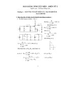
I.The Electric Map
1.Layout diagram
1.Layout diagram
2.Schematic diagram
2.Schematic diagram
3.Wiring Diagram
3.Wiring Diagram
1.Layout diagram
Funtion:Locate loads
2.Schematic diagram
Includes circuit:
-
Three Phase Transformer
6KVA/0.38KV
-
Single phase electric meters
-
CB
-
2 Fuses
-
2 Switch
-
2 Light,2 socket (10A,20A)
10KVA
6KV
0,38KV
10KVA
3 4
KWh
KWh
CB
30A
R
R
R
R
R
K1
K2
K3
10A
20A
1~40
3.Wiring Diagram
6KV/ 0,38KV
10A
20A
KWh
1~40
-
4 light
-
2 switch
-
2 socket
-
Single phase electric meters
-
5 Fuse
- System have wire mass
- Wire on plastic pipe
- Socket distance land 1.3m
- Pile resistance < or = 4 om
Note
Circuits on family
Includes circuit:
- 1 light
-
1 switch
-
2 socket
-
1 Fuses
-
CB
Includes circuit:
- 1 light
-
1 switch
-
1 Fuses
-
CB
-
Socket
II. Power supply cord connection and V.O.M
1.Power supply cord connection
a. direct connection (communication connection head)
- Crossed the wire 2 A and B (already broaching the shell and cleaned)
should join together
- A wire wound on the body B (close to around 10 rounds each)
- B winding wire on the body A (close to each other about 10 rounds)
Use pliers to tighten connections.
b. Branch connections (T-connector):
- Place the wire A wire is perpendicular to the body B (the shell has
been grooming and cleaning).
- Wrap the wire A wire around the body behind the head string B of A,
the first wire wrap
- A round wire A to the front lines A and B wire wound on the body for
about 7 to
10 ring-side.
- Use pliers to tighten connections again
c. Lead solder
- Plug the burner to reach maximum temperature.
- Clean the surface with sandpaper connection.
- Resin dots on the burner (the burner cleaned by acid in the resin).
- Place the burner at an angle of 45 joints dovoi about 3 to 5 minutes
(depending on the type of burner 40W or 60W) for connection to heat up.
- How to put lead solder burner 1 to 2 mm for lead free flowing around the
joints.
- Connect the burner to reach maximum temperature.
- Rats need to shell the string si.
- Clean the surface of the wire.
- Resin dots on the burner (the burner cleaned by acid in the resin).
- Place the burner at an angle of 45 dovoi the wire about 3 to 5 minutes
(depending on the type of burner 40W or 60W) for the wire to heat up.
- How to put lead solder burner 1 to 2 mm for lead free flowing around the
wire.
- Meters VOM meter is called universal because it does much
use.
- VOM meter can measure currents, voltages, resistance. In addition, the
- VOM can be used for Testing Transistor, determine the polarity of the
diode
-
Elevator (A): Calibration for Ohm (Ω-0 from right to left as the Ω-∞).
- Elevator (B) and (C) dividing the Volt, Ampere DC, AC
(DC.VA & AC.V) left to right, the maximum number of 0.
- Scale (D) read Trasistor amplification factor (HFE = Ic / Ib).
-
Elevator (E) and uterus (F): read current polarization upon or against
(leakage) of
Diode.
- Scale (G): one is to read the leaked ICEO of transistors
** Practices
1.Voltage measurements:
- When you want to measure voltage alternating current (AC) or DC
(DC), we adjust
switch on the meter of the measuring period is denoted AC.V or DC.V
- Select appropriate measurement period (larger) with a voltage to be
measured.
- Install parallel to the clock source to be measured.
-
Read the voltage value measured on this scale.
+ 10 volt scale: each bar is 0.2 units.
+ 50 volt scale: each bar unit LA1.
+ 250 volt scale: each bar is 5 units.
For example: choose period, we measured 250 index on the scale read 250
AC.V.
Note: - When measuring AC voltage, attention select appropriate
measurement range, avoiding
-
choose smaller voltage range to be measured or choose another
measurement range
voltage measurement.
2. DC current measurement:
-
- When you want to measure DC DC (DC), we adjust the switch on
clock period of measurement is denoted DC.mA
- Select the period to match the measured current to be measured.
- Install with the serial clock source to be measured.
- Read the voltage value measured on the scale corresponds to the range
measured.
3. Testers
- When you want to measure the electrical resistance R, we adjust the
switch on the measuring range is denoted
Ω.
- Choose a suitable measuring range resistor to be measured.
- Chap 2 measuring stick together and adjust the knob for the needle 0Ω
standards.
- Put the rod 2 measured in the first two resistors to be measured.
- Read the index measured on the scale corresponds to the range
measured.
III Motor 3 phase and motor 1 phase
1. Testers heat engine
Step 1: Measure R insulation (check for shells being touched or not)> 1 mg
- If the first measure in turn the AX, BY, CZ with shell insulation resistance> 1 mg
shall meet the requirements => do not touch the shell => machine operating
conditions
Step 2: Measure R (coil resistance) AX, BY, CZ are equal
- Measure the pairs AX and determine the resistance of the coil day.Sau it shall be
the same for the pair BY, CZ
- Case 1:
1. Voltage coil 3 is measured at several volts, the coil (I, II) will have the
following: A_X_B_Y
2.Neu measuring coil 3 is the U = 0V (X_Y) first rolled coil connecting the
2nd strategy was as follows: A_X_Y_B
-Case 2: After measuring the change determined before the 3rd roll to roll 1 or roll
2 rolls to determine the remainder of the 3rd roll
* Experimental:
Scroll I: 1-4
Scroll II :2-5
Scroll III :3-6
U = 0v
V
V
2.3-phase motor conector
Motor 3 phase Xung shun
Picture of motor 3 phase
Y 90
0
A 105
0
E 120
0
B 130
0
F 155
0
H 180
0
C >180
0
*INS:insclass
*S.F: service factor
*Frame:- structural parameters, such
as structure height of the motor shaft
from the floor, the distance of the axis
of the fixed point the base installation.
- example:Engine Frame: 215, then
we get the first two numbers divided 4
so 5 * 1 / 4, this is the height of the
shaft from the floor and 5 are set
distance from a fixed point on the axis
of the base (inch )
* U
1
U
2
=W
1
W
2
=V
1
V
2
*
3. 1-phase phase motor conector
S. W : stort winding
R. W: run winding
R
R. W
> R
S. W
Experimental: R
R. W
= 50V, R
S. W
=20V
Picture of motor 1 phase