Engineering Tribology Episode 2 Part 6 ppt
Bạn đang xem bản rút gọn của tài liệu. Xem và tải ngay bản đầy đủ của tài liệu tại đây (621.19 KB, 25 trang )
350 ENGINEERING TRIBOLOGY
temperature [56] and this characteristic cannot be neglected in any model of EHL with sliding
present.
EHL Between Meshing Gear Wheels
From the view point of practical engineering an important EHL contact takes place between
the lubricated teeth of opposing gears. As is the case with rolling bearings, it is essential to
maintain an adequate EHL film thickness to prevent wear and pitting of the gear teeth. The
same fundamental equations for EHL film thickness described for a simple Hertzian contact
also apply for gears. However, before applying the formulae for contact parameters and
minimum film thickness it is necessary to define reduced radius of curvature, contact load
and surface velocity for a specific gear. The contact geometry is illustrated in Figure 7.42.
ω
A
ω
B
ω
a
ω
B
ω
A
ψ
ψ
O
B
O
A
C
1
P
S
C
C
2
R
B
R
A
R
A
sinψ +
S
R
B
sinψ − S
Locus of contact
Pitch circle
Base circle
Base circle
Pitch circle
W
W
h
B
h
A
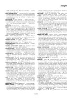
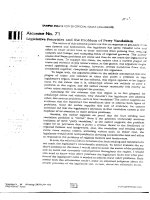
FIGURE 7.42 Contact geometry of meshing involute gear teeth.
The surface contact velocity is expressed as:
U =
U
A
+ U
B
2
=
ω
A
R
A
sinψ+ω
B
R
B
sinψ
2
where:
R
A
, R
B
are the pitch circle radii of the driver and follower respectively [m];
ψ is the pressure angle (acute angle between contact normal and the common
tangent to the pitch circles);
ω
A
, ω
B
are the angular velocities of the driver and follower respectively [rad/s].
Since:
R
A
R
B
=
ω
B
ω
A
Then the contact surface velocity is:
TEAM LRN
ELASTOHYDRODYNAMIC LUBRICATION 351
U = ω
A
R
A
sinψ = ω
B
R
B
sinψ
(7.53)
Assuming that the total load is carried by one tooth only then, from Figure 7.42, the contact
load in terms of the torque exerted is given by:
W =
T
B
h
B
=
T
B
R
B
cosψ
(7.54)
where:
W is the total load on the tooth [N];
h
B
is the distance from the centre of the follower to interception of the locus of the
contact with its base circle, i.e. h
B
= R
B
cosψ [m];
T
B
is the torque exerted on the follower [Nm].
The torque exerted on the driver and the follower expressed in terms of the transmitted
power is calculated from:
T
A
=
H
ω
A
= 9.55
H
N
A
T
B
=
H
ω
B
= 9.55
H
N
B
where:
N
A
, N
B
are the rotational speeds of the driver and follower respectively [rps];
H is the transmitted power [kW].
Substituting into (7.54) yields the contact load. The minimum and central EHL film
thicknesses can then be calculated from formulae (7.26) and (7.27).
The line from ‘C
1
’ to ‘C
2
’ (Figure 7.42) is the locus of the contact and it can be seen that the
distance ‘S’ between the gear teeth contact and the pitch line is continuously changing with
the contact position during the meshing cycle of the gears. It is thus possible to model any
specific contact position on the tooth surface of an involute gear by two rotating circular discs
of radii (R
A
sinΨ + S) and (R
B
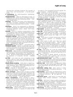
sin Ψ - S) as shown in Figure 7.42. This idea is applied in a
testing apparatus generally known as a ‘twin disc’ or ‘two disc‘ machine shown schematically
in Figure 7.43. Since the gear tooth contact is closely simulated by the two rotating discs, these
machines are widely used to model gear lubrication and wear and in selecting lubricants or
materials for gears. It is much cheaper and more convenient experimentally to use metal
discs instead of actual gears for friction and wear testing. The wear testing virtually ensures
the destruction of the test specimens and it is far easier to inspect and analyse a worn disc
surface than the recessed surface of a gear wheel.
It may also be apparent that the fixed dimensions of the discs only allow modelling of one
particular position in the contact cycle. Of particular importance to friction and wear studies
is the increasing amount of sliding as the contact between opposing gear teeth moves away
from the line of shaft centres. The radii of curvature also vary with position of gear teeth so
that the ‘two-disc’ test rig is not entirely satisfactory and another model gear apparatus such
as the ‘Ryder gear tester’ may be necessary for some studies. A recently developed test-
apparatus where two contacting discs are supplied with additional movement of their
corresponding shafts allows a much closer, more realistic simulation of the entire gear tooth
contact cycle [68].
TEAM LRN
352 ENGINEERING TRIBOLOGY
ω
A
ω
B
R
B
sinψ − S
W
R
A
sinψ + S
W
FIGURE 7.43 Schematic diagram of a ‘two disc‘ machine used to simulate rolling/sliding
contact in meshing gears, i.e.: for S = 0 pure rolling and for S ≠ 0 rolling/sliding
in EHL contact; S is the distance between the pitch line and the gear teeth
contact [m].
7.8 SUMMARY
A fundamental lubrication mechanism involved in highly loaded concentrated contacts was
discussed in this chapter. The remarkable efficiency of elastohydrodynamic lubrication in
preventing solid to solid contact even under extreme contact stresses prevents the rapid
destruction of many basic mechanical components such as rolling bearings or gears. EHL is,
however, mostly confined to mineral or synthetic oils since it is essential that the lubricant is
piezo-viscous. The mechanism of EHL involves a rapid change in the lubricant from a
nearly ideal liquid state outside of the contact to an extremely viscous or semi-solid state
within the contact. This transformation allows the lubricant to be drawn into the contact by
viscous drag while generating sufficient contact stress within the contact to separate the
opposing surfaces. If a simple solid, i.e. a fine powder, is supplied instead, there is no viscous
drag to entrain the powder and consequently only poor lubrication results. A non-piezo-
viscous lubricant simply does not achieve the required high viscosity within the contact
necessary for the formation of the lubricating film. The formulae for the calculation of the
EHL film thickness are relatively simple and are based on load, velocity, dimensions and
elastic modulus of the contacting materials. As well as providing lubrication of concentrated
contacts, the EHL mechanism can be used to generate traction, i.e. where frictional forces
enable power transmission. A unique combination of high tractive force with minimal wear,
reduced noise levels, infinitely variable output speed and an almost constant torque over the
speed range can be obtained by this means.
REFERENCES
1 A.N. Grubin, Fundamentals of the Hydrodynamic Theory of Lubrication of Heavily Loaded Cylindrical
Surfaces, in Investigation of the Contact Machine Components, Kh.F. Ketova, ed. Translation of Russian Book
No. 30, Central Scientific Institute for Technology and Mechanical Engineering, Moscow, 1949.
2 H.M. Martin, Lubrication of Gear Teeth, Engineering, London, Vol. 102, 1916, pp. 119-121.
3 D. Dowson and G.R. Higginson, Elastohydrodynamic Lubrication, Pergamon Press, Oxford, 1977.
4 A.W. Crook, Elastohydrodynamic Lubrication of Rollers, Nature, Vol. 190, 1961, pp. 1182.
5 A. Cameron and R. Gohar, Optical Measurement of Oil Film Thickness under Elasto-hydrodynamic
Lubrication, Nature, Vol. 200, 1963, pp. 458-459.
TEAM LRN
ELASTOHYDRODYNAMIC LUBRICATION 353
6 H. Hertz, Uber die Beruhrung Fester Elastischer Korper, (On the Contact of Elastic Solids), J. Reine und
Angewandte Mathematik, Vol. 92, 1881, pp. 156-171.
7 B.J. Hamrock and D. Dowson, Ball Bearing Lubrication, The Elastohydrodynamics of Elliptical Contacts,
John Willey & Sons, 1981.
8 H. Hertz, Miscellaneous Papers by H. Hertz, Jones & Schott (eds), Macmillan, London, 1986.
9 K.L. Johnson, Contact Mechanics, Cambridge University Press, 1985.
10 B.J. Hamrock and W.J. Anderson, Analysis of an Arched Outer-Race Ball Bearing Considering Centrifugal
Forces, Transactions ASME, Journal of Lubrication Technology, Vol. 95, 1973, pp. 265-276.
11 R. Gohar, Elastohydrodynamics, Ellis Horwood Limited, 1988.
12 D.E. Brewe and B.J. Hamrock, Simplified Solution for Elliptical Contact Deformation Between Two Elastic
Solids, Transactions ASME, Journal of Lubrication Technology, Vol. 99, 1977, pp. 485-487.
13 F.T. Barwell, Bearing Systems, Principles and Practice, Oxford University Press, 1979.
14 Engineering Sciences Data Unit, Stress and Strength Sub-Series, Contact Stresses, Vol. 9, No. 78035, 1985.
15 H. Christensen, The Oil Film in a Closing Gap, Proc. Roy. Soc., London, Series A, Vol. 266, 1962, pp. 312-328.
16 B.J. Hamrock and D. Dowson, Isothermal Elastohydrodynamic Lubrication of Point Contacts, Part III - Fully
Flooded Results, Transactions ASME, Journal of Lubrication Technology, Vol. 99, 1977, pp. 264-276.
17 K.A. Kaye and W.O. Winer, An Experimental Evaluation of the Hamrock and Dowson Minimum Film
Thickness Equation for Fully Flooded EHD Point Contact, Transactions ASME, Journal of Lubrication
Technology, Vol. 103, 1981, pp. 284-294.
18 D. Dowson and A.V. Whitaker, A Numerical Procedure for the Solution of the Elastohydrodynamic Problems
of Rolling and Sliding Contacts Lubricated by Newtonian Fluid, Proc. Inst. Mech. Engrs., London, Vol. 180, Pt.
3B, 1965-1966, pp. 57-71.
19 B.J. Hamrock and D. Dowson, Minimum Film Thickness in Elliptical Contacts for Different Regimes of Fluid-
Film Lubrication, Proc. 5th Leeds-Lyon Symp. on Tribology, Elastohydrodynamics and Related Topics,
editors: D. Dowson, C.M. Taylor, M. Godet and D. Berthe, Sept. 1978, Inst. Mech. Engrs. Publ., London, 1979,
pp. 22-27.
20 A.W. Crook, The Lubrication of Rollers, Part I, Phil. Trans. Roy. Soc., London, Series A, Vol. 250, 1958, pp.
387-409.
21 A. Dyson, H. Naylor and A.R. Wilson, The Measurement of Oil Film Thickness in Elastohydrodynamic
Contacts, Proc. Inst. Mech. Engrs., Vol. 180, Pt. 3B, 1965, pp. 119-134.
22 L.B. Sibley, J.C. Bell, F.K. Orcutt and C.M. Allen, A Study of the Influence of Lubricant Properties on the
Performance of Aircraft Gas Engine Rolling Contact Bearings, WADD Technical Report, 1960, pp. 60-189.
23 L.B. Sibley and A.E. Austin, An X-Ray Method for Measuring Thin Lubricant Films Between Rollers, ISA
Transactions, Vol. 3, 1962, pp. 237-243.
24 D.R. Meyer and C.C. Wilson, Measurement of Elastohydrodynamic Oil Film Thickness and Wear in Ball
Bearings by the Strain Gage Method, Transactions ASME, Journal of Lubrication Technology, Vol. 93, 1971,
pp. 224-230.
25 A.T. Kirk, Hydrodynamic Lubrication of Perspex, Nature, Vol. 194, 1962, pp. 965-966.
26 A. Cameron and R. Gohar, Theoretical and Experimental Studies of the Oil Film in Lubricated Point
Contacts, Proc. Roy. Soc., London, Series A, Vol. 291, 1966, pp. 520-536.
27 N. Thorp and R. Gohar, Oil Film Thickness and Shape for Ball Sliding in a Grooved Raceway, Transactions
ASME, Journal of Lubrication Technology, Vol. 94, 1972, pp. 199-210.
28 D. Dowson, Recent Developments in Studies of Fluid Film Lubrication, Proc. Int. Tribology Conference,
Melbourne, The Institution of Engineers, Australia, National Conference Publication No. 87/18, December,
1987, pp. 353-359.
29 T.E. Tallian, On Competing Failure Modes in Rolling Contact, ASLE Transactions, Vol. 10, 1967, pp. 418-439.
30 K.L. Johnson, J.A. Greenwood and S.Y. Poon, A Simple Theory of Asperity Contact in Elastohydrodynamic
Lubrication, Wear, Vol. 19, 1972, pp. 91-108.
31 J.A. Greenwood and J.B.P. Williamson, Contact of Nominally Flat Surfaces, Proc. Roy. Soc., London, Series A,
Vol. 295, 1966, pp. 300-319.
32 T.E. Tallian and J.I. McCool, An Engineering Model of Spalling Fatigue Failure in Rolling Contact, II. The
Surface Model, Wear, Vol. 17, 1971, pp. 447-461.
TEAM LRN
354 ENGINEERING TRIBOLOGY
33 R.S. Sayles, G.M.S. deSilva, J.A. Leather, J.C. Anderson and P.B. Macpherson, Elastic Conformity in
Hertzian Contacts, Tribology International, Vol. 14, 1981, pp. 315-322.
34 G.M.S. De Silva, J.A. Leather and R.S. Sayles, The Influence of Surface Topography on Lubricant Film
Thickness in EHD Point Contact, Proc. 12th Leeds-Lyon Symp. on Tribology, Mechanisms and Surface Distress:
Global Studies of Mechanisms and Local Analyses of Surface Distress Phenomena, editors: D. Dowson, C.M.
Taylor, M. Godet and D. Berthe, Sept. 1985, Inst. Mech. Engrs. Publ., London, 1986, pp. 258-272.
35 N. Patir and H.S. Cheng, Effect of Surface Roughness Orientation on the Central Film Thickness in EHD
Contacts, Proc. 5th Leeds-Lyon Symp. on Tribology, Elastohydrodynamics and Related Topics, editors: D.
Dowson, C.M. Taylor, M. Godet and D. Berthe, Sept. 1978, Inst. Mech. Engrs. Publ., London, 1979, pp. 15-21.
36 H.S. Cheng, On Aspects of Microelastohydrodynamic Lubrication, Proc. 4th Leeds-Lyon Symp. on Tribology,
Surface Roughness Effects in Lubrication, editors: D. Dowson, C.M. Taylor, M. Godet and D. Berthe, Sept.
1977, Inst. Mech. Engrs. Publ., London, 1978, pp. 71-79.
37 X. Ai and L. Zheng, A General Model for Microelastohydrodynamic Lubrication and its Full Numerical
Solution, Transactions ASME, Journal of Tribology, Vol. 111, 1989, pp. 569-576.
38 P. Goglia, T.F. Conry and C. Cusano, The Effects of Surface Irregularities on the Elastohydrodynamic
Lubrication of Sliding Line Contacts, Parts 1 and 2, Transactions ASME, Journal of Tribology, Vol. 106, 1984,
Part 1, pp. 104-112, Part 2, pp. 113-119.
39 C.C. Kweh, H.P. Evans and R.W. Snidle, Micro-Elastohydrodynamic Lubrication of an Elliptical Contact
With Transverse and 3-D Sinusoidal Roughness, Transactions ASME, Journal of Tribology, Vol. 111, 1989, pp.
577-584.
40 L. Chang and M.N. Webster, A Study of Elastohydrodynamic Lubrication of Rough Surfaces, Transactions
ASME, Journal of Tribology, Vol. 113, 1991, pp. 110-115.
41 L.G. Houpert and B.J. Hamrock, EHD Lubrication Calculation Used as a Tool to Study Scuffing, Proc. 12th
Leeds-Lyon Symp. on Tribology, Mechanisms and Surface Distress: Global Studies of Mechanisms and Local
Analyses of Surface Distress Phenomena, editors: D. Dowson, C.M. Taylor, M. Godet and D. Berthe, Sept.
1985, Inst. Mech. Engrs. Publ., London, 1986, pp. 146-155.
42 K.P. Baglin, EHD Pressure Rippling in Cylinders Finished With a Circumferential Lay, Proc. Inst. Mech.
Engrs, Vol. 200, 1986, pp. 335-347.
43 B. Michau, D. Berthe and M. Godet, Influence of Pressure Modulation in Line Hertzian Contact on the Internal
Stress Field, Wear, Vol. 28, 1974, pp. 187-195.
44 J.F. Archard and R.A. Rowntree, The Temperature of Rubbing Bodies, Part 2, The Distribution of Temperature,
Wear, Vol. 128, 1988, pp. 1-17.
45 F.P. Bowden and D. Tabor, Friction and Lubricating Wear of Solids, Part 1, Oxford: Clarendon Press, 1964.
46 H. Blok, Theoretical Study of Temperature Rise at Surfaces of Actual Contact Under Oiliness Lubricating
Conditions, General Discussion on Lubrication, Inst. Mech. Engrs, London, Vol. 2, 1937, pp. 222-235.
47 J.C. Jaeger, Moving Sources of Heat and the Temperature at Sliding Contacts, Proc. Roy. Soc., N.S.W., Vol. 76,
1943, pp. 203-224.
48 J.F. Archard, The Temperature of Rubbing Surfaces, Wear, Vol. 2, 1958/59, pp. 438-455.
49 F.E. Kennedy, Thermal and Thermomechanical Effects in Dry Sliding, Wear, Vol. 100, 1984, pp. 453-476.
50 H. Blok, The Postulate About the Constancy of Scoring Temperature, Interdisciplinary Approach to
Lubrication of Concentrated Contacts, P.M. Ku (ed.), Washington DC, Scientific and Technical Information
Division, NASA, 1970, pp. 153-248.
51 T.A. Stolarski, Tribology in Machine Design, Heineman Newnes, 1990.
52 V.K. Ausherman, H.S. Nagaraj, D.M. Sanborn and W.O. Winer, Infrared Temperature Mapping in
Elastohydrodynamic Lubrication, Transactions ASME, Journal of Lubrication Technology, Vol. 98, 1976, pp.
236-243.
53 V.W. King and J.L. Lauer, Temperature Gradients Through EHD Films and Molecular Alignment Evidenced
by Infrared Spectroscopy, Transactions ASME, Journal of Lubrication Technology, Vol. 103, 1981, pp. 65-73.
54 A.R. Wilson, An Experimental Thermal Correction for Predicted Oil Film Thickness in Elastohydrodynamic
Contacts, Proc. 6th Leeds-Lyon Symp. on Tribology, Thermal Effects in Tribology, Sept. 1979, editors: D.
Dowson, C.M. Taylor, M. Godet and D. Berthe, Inst. Mech. Engrs. Publ., London, 1980, pp. 179-190.
55 J.L. Tevaarwerk, Traction Calculations Using the Shear Plane Hypothesis, Proc. 6th Leeds-Lyon Symp. on
Tribology, Thermal Effects in Tribology, Sept. 1979, editors: D. Dowson, C.M. Taylor, M. Godet and D. Berthe,
Inst. Mech. Engrs. Publ., London, 1980, pp. 201-215.
TEAM LRN
ELASTOHYDRODYNAMIC LUBRICATION 355
56 H.A. Spikes and P.M. Cann, The Influence of Sliding Speed and Lubricant Shear Stress on EHD Contact
Temperatures, Tribology Transactions, Vol. 33, 1990, pp. 355-362.
57 W.O. Winer and E.H. Kool, Simultaneous Temperature Mapping and Traction Measurements in EHD
Contacts, Proc. 6th Leeds-Lyon Symp. on Tribology, Thermal Effects in Tribology, Sept. 1979, editors: D.
Dowson, C.M. Taylor, M. Godet and D. Berthe, Inst. Mech. Engrs. Publ., London, 1980, pp. 191-200.
58 T.A. Dow and W. Kannel, Evaluation of Rolling/Sliding EHD Temperatures, Proc. 6th Leeds-Lyon Symp. on
Tribology, Thermal Effects in Tribology, Sept. 1979, editors: D. Dowson, C.M. Taylor, M. Godet and D. Berthe,
Inst. Mech. Engrs. Publ., London, 1980, pp. 228-240.
59 K.L. Johnson and J.A. Greenwood, Thermal Analysis of an Eyring Fluid in Elastohydrodynamic Traction,
Wear, Vol. 61, 1980, pp. 353-374.
60 J.L. Lauer and Y-J. Ahn, Lubricants and Lubricant Additives Under Shear Studied Under Operating
Conditions by Optical and Infra Red Spectroscopic Methods, Tribology Transactions, Vol. 31, 1988, pp. 120-
127.
61 P.M. Cann and H.A. Spikes, In Lubro Studies of Lubricants in EHD Contacts Using FITR Absorption
Spectroscopy, Tribology Transactions, Vol. 34, 1991, pp. 248-256.
62 F.L. Snyder, J. L. Tevaarwerk and J. A. Schey, Effects of Oil Additives on Lubricant Film Thickness and
Traction, SAE Tech. Paper No. 840263, 1984.
64 M. Alsaad, S. Bair, D.M. Sanborn and W.O. Winer, Glass Transitions in Lubricants: Its Relation to
Elastohydrodynamic Lubrication (EHD), Transactions ASME, Journal of Lubrication Technology, Vol. 100,
1978, pp. 404-417.
63 S. Bair and W.O. Winer, Some Observations in High Pressure Rheology of Lubricants, Transactions ASME,
Journal of Lubrication Technology, Vol. 104, 1982, pp. 357-364.
65 M. Kaneta, H. Nishikawa and K. Kameishi, Observation of Wall Slip in Elastohydrodynamic Lubrication,
Transactions ASME, Journal of Tribology, Vol. 112, 1990, pp. 447-452.
66 K.L. Johnson and J.G. Higginson, A Non-Newtonian Effect of Sliding in Micro-EHL, Wear, Vol. 128, 1988, pp.
249-264.
67 K.L. Johnson and J.L. Tevaarwerk, Shear Behaviour of Elastohydrodynamic Oil Films, Proc. Roy. Soc.,
London, Series A, Vol. 356, 1977, pp. 215-236.
68 E. Van Damme, Surface Engineering, Gear Wear Simulations, Proc. International Tribology Conference,
Melbourne, 1987, The Institution of Engineers, Australia, National Conference Publication No. 87/18,
December, 1987, pp. 391-396.
69 C.A. Foord, W.C. Hammann and A. Cameron, Evaluation of Lubricants Using Optical Elastohydrodynamics,
ASLE Transactions, Vol. 11, 1968, pp. 31-43.
70 P.L. Wong, P.Huang, W. Wang and Z. Zhang, Effect of Geometry Change of Rough Point Contact Due to
Lubricated Sliding Wear on Lubrication, Tribology Letters, Vol. 5, 1998, pp. 265-274.
71 C. Bovington, Elastohydrodynamic Lubrication: a Lubricant Industry Perspective, Proc. Inst. Mech. Eng., Part
J, Journal of Engineering Tribology, Vol. 213, 1999, pp. 417-426.
TEAM LRN
356 ENGINEERING TRIBOLOGY
TEAM LRN
EXTREMEBOUNDARY
8
PRESSURE LUBRICATION
AND
8.1 INTRODUCTION
In many practical applications there are cases where the operating conditions are such that
neither hydrodynamic nor EHL lubrication is effective. The question then is: how are the
interacting machine components lubricated and what is the lubrication mechanism
involved? The models of lubrication which are thought to operate under such conditions are
discussed in this chapter. The traditional name for this type of lubrication is ‘boundary
lubrication’ or ‘boundary and extreme-pressure lubrication’. Neither of these terms describe
accurately the processes at work since they were conceived long before any fundamental
understanding of the mechanisms was available. Several specialized modes of lubrication
such as adsorption, surface localized viscosity enhancement, amorphous layers and sacrificial
films are commonly involved in this lubrication regime to ensure the smooth-functioning
and reliability of machinery. The imprecise nature of present knowledge about these modes
or mechanisms of lubrication contrasts with their practical importance. Many vital items of
engineering equipment such as steel gears, piston-rings and metal-working tools depend on
one or more of these lubrication modes to prevent severe wear or high coefficients of friction
and seizure.
Boundary and E.P. lubrication is a complex phenomenon. The lubrication mechanisms
involved can be classified in terms of relative load capacity and limiting frictional
temperature as shown in Table 8.1, and they will be described in this chapter.
These lubrication mechanisms are usually controlled by additives present in the oil. Since
the cost of a lubricant additive is usually negligible compared to the value of the mechanical
equipment, the commercial benefits involved in this type of lubrication can be quite large.
In general, boundary and E.P. lubrication involves the formation of low friction, protective
layers on the wearing surfaces. One exception is when the surface-localized viscosity
enhancement takes place. The occurrence of surface-localized viscosity enhancement,
however, is extremely limited as is explained in the next section.
The operating principle of the boundary lubrication regime can perhaps be best illustrated by
considering the coefficient of friction. In simple terms the coefficient of friction ‘µ’ is defined
as the ratio of frictional force ‘F’ and the load applied normal to the surface ‘W’, i.e.:
µ = F/W (8.1)
TEAM LRN
358 ENGINEERING TRIBOLOGY
TABLE 8.1 Categories of boundary and E.P. lubrication.
Temperature Load Lubrication mechanisms
Low
Low
High
High
Medium
High
Viscosity enhancement close to contacting surface, not specific to
lubricant.
Friction minimization by coverage of contacting surfaces with
adsorbed mono-molecular layers of surfactants.
Irreversible formation of soap layers and other viscous materials on
worn surface by chemical reaction between lubricant additives and
metal surface.
Surface-localized viscosity enhancement specific to lubricant additive
and basestock.
Formation of amorphous layers of finely divided debris from reaction
between additives and substrate metal surface.
Reaction between lubricant additives and metal surface.
Formation of sacrificial films of inorganic material on the worn
surface preventing metallic contact and severe wear.
Since the contacting surfaces are covered by asperities, ‘dry’ contact is established between the
individual asperities and the ‘true’ total contact area is the sum of the individual contact
areas between the asperities. Assuming that the major component of the frictional force is
due to adhesion between the asperities (other effects, e.g. ploughing, are negligible), then the
expression for frictional force ‘F’ can be written as:
F = A
t
τ
where:
F is the frictional force [N];
A
t
is the true contact area [m
2
];
τ is the effective shear stress of the material [Pa].
Applied load can be expressed in terms of contact area, i.e.:
W = A
t
p
y
where:
p
y
is the plastic flow stress of the material (close in value to the indentation
hardness) [Pa].
Substituting for ‘F’ and ‘W’ to (8.1) yields:
µ = τ/p
y
(8.2)
This simple model explains the rationale behind boundary lubrication. It can be seen from
equation (8.2) that in order to obtain a low coefficient of friction, material of low shear
strength and high hardness is required. These requirements are clearly incompatible.
However, if a low shear-strength layer can be formed on a hard substrate then low
coefficients of friction can be achieved. Thus, in general terms, the fundamental principles
behind boundary and E.P. lubrication involve the formation of low shear-strength
lubricating layers on hard substrates. It is evident that, since with most materials the ratio of
‘τ’ and ‘p
y
’ does not vary greatly, changing the material type has little effect on friction.
TEAM LRN
BOUNDARY AND EXTREME PRESSURE LUBRICATION 359
8.2 LOW TEMPERATURE - LOW LOAD LUBRICATION MECHANISMS
For a very large range of sliding speeds and loads, classical hydrodynamic lubrication prevails
in a lubricated contact. As the sliding speed is reduced, hydrodynamic lubrication reaches its
limit where the hydrodynamic film thickness declines until eventually the asperities of the
opposing surfaces interact. This process was originally investigated by Stribeck and has
already been discussed in Chapter 4.
At low speeds, under certain conditions, contact between opposing surfaces can be prevented
by the mechanism involving surface-localized viscosity enhancement. In other words, a thin
layer of liquid with an anomalously high viscosity can form on the contacting surfaces.
Hydrodynamic lubrication or quasi-hydrodynamic lubrication then persists to prevent solid
contact and severe wear. In such cases linear molecules of a hydrocarbon align themselves
normally to the contacting surfaces to form a lubricating, protective layer as shown in Figure
8.1. Since the molecules are polar the opposite ends are attracted to form pairs of molecules
which are subsequently incorporated into the viscous surface layer. At the interface with the
metallic substrate the attractive force of the free end of the molecules to the substrate is
sufficient to firmly bond the entire layer.
FIGURE 8.1 Low-temperature, low-load mechanism of lubrication [1].
It has been found that linear molecules are more effective than other hydrocarbons in
preventing solid contact. The variation in film thickness between parallel discs as a function
of the square root of squeeze time for paraffinic oil and cyclohexane is shown in Figure 8.2 [2].
According to the theory of hydrodynamic lubrication described in Chapter 4, there is a linear
decline in film thickness with square root of squeeze time but as can be seen from Figure 8.2
this linearity is soon lost. The MS-20 oil contains paraffinic molecules which are
approximately linear and this allows for the formation and persistence of a thicker film than
for cyclohexane. Cyclohexane is a non-linear molecule which impedes the linear alignment
of molecules and therefore the resulting film is less effective in preventing solid contact.
The effectiveness of this mechanism of lubrication is limited to low temperatures and low
loads. The data shown in Figure 8.2 was obtained at contact pressures of 0.4 [MPa], and further
work revealed that at contact pressures beyond 2 [MPa] the residual film thickness is very
small [2]. Since in many contacts pressures in the range of 1 [GPa] are quite common, the
TEAM LRN
360 ENGINEERING TRIBOLOGY
disadvantages of this lubrication mechanism are obvious. The temperature also has a
pronounced effect on these films. It was found that even relatively low operating
temperatures of about 50°C can result in severe decline in the film thickness [2]. Since the
practical applications in which this mode of boundary lubrication occurs are extremely
limited, the topic does not incite much technological interest and has consequently been
neglected by most researchers.
0
0.1
0.2
0.3
0.4
Minimum film thickness [µm]
0 102030405060708090100
t [s
0.5
]
0.25 0.5 1 1.5 2 2.5
Time [h]
0
Paraffinic oil MS-20
Cyclohexane
Measured at a contact
pressure of 0.4 MPa
FIGURE 8.2 Detection of permanent films formation as evidence of a surface-proximal layer
of aligned molecules [2].
8.3 LOW TEMPERATURE - HIGH LOAD LUBRICATION MECHANISMS
The lubrication mechanism acting at low temperature and high load is of considerable
practical importance. It is generally known as ‘adsorption lubrication’. This mechanism of
lubrication is quite effective with contact pressures up to 1 [GPa] and relatively low surface
temperatures between 100 - 150°C. Adsorption lubrication is different from either
hydrodynamic, EHL or even the viscous layer described in the previous section in that the
opposing contact surfaces are not separated by a thick layer of fluid. A mono-molecular layer
separates the contacting surfaces and this layer is so thin that the mechanics of asperity
contact are identical to that of dry surfaces in contact. This mono-molecular layer is formed
by adsorption of the lubricant or, more precisely, lubricant additives on the worn surface. The
lubricating effect or friction reduction is caused by the formation of a low shear strength
interface between the opposing surfaces.
It can be seen from equation (8.2) that the role of adsorption lubrication is to reduce the
effective shear stress ‘τ’ at the interface without affecting the plastic flow stress ‘p
y
’ of the
substrate. This is achieved by the formation of an adsorbed film on the surface which
introduces a plane of weakness parallel to the plane of sliding. This principle is illustrated in
Figure 8.3 which shows a schematic comparison of contact between dry unlubricated solids
and solids with a lubricant film on asperity peaks.
If the film is thin, then any structural weakness in the direction of the contact load will be
compensated by the substrate. The shear stress anisotropy or low shear stress in the plane of
sliding is obtained by inducing a discontinuity in intermolecular bonding between opposite
TEAM LRN
BOUNDARY AND EXTREME PRESSURE LUBRICATION 361
sides of the sliding interface. At all locations other than the interface, bonding between atoms
even of different substances, e.g. film material and substrate, is relatively strong. The
characteristics of adsorbed layers, in particular of polar organic substances, allow this system
to form on metallic surfaces. The reasons for this are discussed next.
Ιnterfacial shear strength
of the surface layer
Small shear stress at interfaces
Contact stresses remain unaffected
Interfacial shear strength
same as substrate
material
Direct contact between
clean (dry) surfaces
Surfaces with low interfacial shear stress
FIGURE 8.3 Lubrication by a low shear strength layer formed at asperity peaks.
Model of Adsorption on Sliding Surfaces
Organic polar molecules such as fatty acids and alcohols adsorb on to metallic surfaces and
are not easily removed. Speculation about the role of these substances in lubrication has a
long history [3]. Effective adsorption is the reason why a metallic surface still feels greasy or
slippery after being wetted by a fatty substance and will remain greasy even after vigorous
wiping of the surface by a dry cloth. Adsorption on a metallic surface of organic polar
molecules produces a low friction, mono-molecular layer on the surface as shown in Figure
8.4. The polarity of the adsorbate is essential to the lubrication mechanism. Polarity means
that a molecule is asymmetrical with a different chemical affinity at either end of the
molecule. For example, one end of a molecule which is the carboxyl group of a fatty acid,
‘-COOH’, is strongly attracted to the metallic surface while the other end which is an alkyl
group, ‘-CH
3
’, is repellant to almost any other substance.
Strong adsorption ensures that almost every available surface site is occupied by the fatty acid
to produce a dense and robust film. The repulsion or weak bonding between the contacting
alkyl groups ensures that the shear strength of the interface is relatively low. The ratio of τ/p
y
and therefore the friction coefficient is low compared to bare metallic surfaces in contact. This
is the adsorption model of lubrication first postulated by Hardy and Doubleday [4,5] and later
developed by Bowden and Tabor [6]. The fatty acids are particularly effective because of their
strong polarity, but other organic compounds such as alcohols and amines have sufficient
polarity to be of practical use.
TEAM LRN
362 ENGINEERING TRIBOLOGY
Intermolecular contact
and load support
Carboxyl group
(i.e. −COOH)
Alkyl tail
(i.e. −CH
3
)
Fatty
acid
molecule
Weak bonding or repulsion between
opposing −CH
3
groups provides low
interfacial shear stress
Strong bonding between carboxyl
group and substrate
2 nm approximately
FIGURE 8.4 Low friction mono-molecular layer of adsorbed organic polar molecules on
metallic surfaces.
From the view point of lubrication, adsorption can be divided into two basic categories:
‘physisorption’ and ‘chemisorption’. The latter generally occurs at higher temperatures than
the former and is consequently more useful as a lubrication mechanism in practical
applications.
· Physisorption
Physisorption or ‘physical adsorption’ is the classical form of adsorption. Molecules of
adsorbate may attach or detach from a surface without any irreversible changes to the surface
or the adsorbate. Most liquids and gases physisorb to most solid surfaces, but there is almost
always an upper temperature limit to this process. In physisorption van der Waals or
dispersion forces provide the bonding between substrate and adsorbate as illustrated in
Figure 8.5.
Adsorbate
Van der Waals, dispersion
forces, or other low-energy
bonding mechanism
Substrate
FIGURE 8.5 Schematic illustration of physisorption.
Physisorption is effective in reducing friction provided that temperatures do not rise much
above ambient temperature. This effect is illustrated in Figure 8.6 where the results from
friction experiments with a steel ball traversing a platinum or a copper surface covered with
a paraffin (docosane) or a fatty acid (lauric) are shown [6]. Docosane is a straight hydrocarbon
TEAM LRN
BOUNDARY AND EXTREME PRESSURE LUBRICATION 363
without any carboxyl groups, while lauric acid is a fatty acid similar to stearic acid but has a
shorter chain length. The shorter chain length usually results in poorer lubricating capacity
for the same conditions.
0 100 200
Temperature [°C]
0
0.1
0.2
0.3
0.4
0.5
µ
max
AB CD
A Paraffin (docosane)
lubricating platinum
B Fatty acid (lauric)
lubricating platinum
C Copper laurate
lubricating platinum
D Fatty acid (lauric)
lubricating copper
FIGURE 8.6 Effect of temperature on friction of platinum and copper surfaces lubricated by
docosane and lauric acid [6].
It can be seen from Figure 8.6 that there is a sharp rise in friction at some ‘transition
temperature’ which is about 45°C for the platinum surfaces lubricated by docosane and about
70°C for the platinum surfaces lubricated with lauric acid. A similar sharp increase in friction
is observed for copper laurate applied to platinum and lauric acid applied to copper but the
transition temperatures are much higher, about 95°C. The difference in performance between
copper and platinum is that the former has sufficient reactivity to induce chemisorption and
to produce a mono-molecular layer of copper laurate. Similar friction characteristics are
achieved when copper laurate is directly applied to platinum. The friction transition
temperatures manifested by sharp rises in friction for docosane and lauric acid lubricating
platinum occurred at temperatures close to the melting points of docosane (44°C) and stearic
acid (69°C). This proximity is not coincidental and relates to the phenomenon of surface
melting of the monomolecular layer of adsorbate [7]. An ordered layer of adsorbate is critical
to the effectiveness of adsorption lubrication. When the melting point is exceeded this order
is lost and the adsorbed film ceases to function as a lubricating layer, as illustrated
schematically in Figure 8.7.
Where physisorbed films are well established, there is strong evidence that the adsorbate
molecules form a close-packed normally aligned layer. Early studies revealed that the average
area per molecule of n-octadecylamine on platinum was 0.3 [nm
2
] [8]. In a later more accurate
study using radio-actively labelled stearic acid, a packing density of 0.189 [nm
2
] per molecule
was found [9]. This is very close to the theoretical maximum packing density of 0.185 [nm
2
]
per molecule.
Breakdown in the structure of a physisorbed film with increasing temperature was also
studied by X-ray diffraction methods [10-13]. The X-ray diffraction pattern from the adsorbed
TEAM LRN
364 ENGINEERING TRIBOLOGY
film was observed only at low temperatures. As the temperature increased, this pattern
gradually faded to reveal the pattern of the underlying metal. In a separate study it was also
demonstrated that breakdown of the low temperature crystalline structure of fatty acids
occurred on platinum at a temperature close to the melting point of each acid [14].
Below critical temperature
Substrate
Ordered film analogous to solid
Above critical temperature
Substrate
Disordered film analogous to liquid
FIGURE 8.7 Surface melting of adsorbed film.
· Chemisorption
Chemisorption or ‘chemical adsorption’ is an irreversible or partially irreversible form of
adsorption which involves some degree of chemical bonding between adsorbate and
substrate as illustrated schematically in Figure 8.8.
Since most common metals, e.g. iron, are reactive, this form of adsorption has practical
significance. The strength of chemical bonding between the adsorbate and substrate which
affects the friction transition temperature depends on the reactivity of the substrate material
as shown in Table 8.2 [15]. All the materials listed in Table 8.2 were lubricated with lauric acid
and the friction transition temperature was determined. The fraction of lauric acid reacting
with the metallic surface expressed in terms of the percentage of a retained monolayer after
washing was also measured by radio-tracers.
Adsorbate
Strong bonding via electron
exchange with substrate atoms
Substrate
e
-
e
-
e
-
e
-
e
-
e
-
e
-
e
-
e
-
e
-
FIGURE 8.8 Mechanism of chemisorption.
It can be seen from Table 8.2 that zinc, cadmium, copper and magnesium are comparatively
well lubricated by lauric acid with low coefficients of friction and high transition
temperatures. The common characteristic of all these metals is that some of the lauric acid
has been irreversibly adsorbed onto the metallic surface, even though magnesium shows
anomalously low reactivity. On the other hand the inert metals such as platinum and silver
show high friction coefficients and low transition temperatures. Glass, which is virtually
inert, is also poorly lubricated by lauric acid. No permanent retention of lauric acid is found
on platinum, silver or glass. Other metals such as nickel, aluminium and chromium also
conform to the pattern of high friction coefficient and poor retention of lauric acid. The
reasons for the low reactivity of these metals are, however, still unclear.
TEAM LRN
BOUNDARY AND EXTREME PRESSURE LUBRICATION 365
T
ABLE 8.2 Frictional data for lauric acid lubricating metals of varying reactivity [15].
Zinc 0.04 94 10.0 Smooth
Cadmium 0.05 103 9.3 Smooth
Copper 0.08 97 4.6 Smooth
Magnesium 0.08 80 Trace Smooth
Platinum 0.25 20 0.0 Intermittent
Nickel 0.28 20 0.0 Intermittent
Aluminium 0.30 20 0.0 Intermittent
Chromium 20 Trace Intermittent
Glass 20 0.0 Intermittent (irregular)
Silver 0.55 20 0.0 Intermittent (marked)
0.34
0.3 − 0.4
Material
Coefficient of
friction at 20°C
Transition
temperature [°C]
% acid*
reacting
Type of sliding
at 20°C
* Estimated amount of acid involved in the reaction assuming formation of a normal salt.
A major difference between chemisorption and physisorption is that chemisorbed films are,
at least in part, irreversibly bound to the substrate surface. Even washing by strong solvents,
which removes physisorbed films, does not remove chemisorbed films. It was found
experimentally, for example, that while some stearic acid was removed by strong solvents a
certain minimum quantity equal to 38% of a close packed monolayer always remained [9].
However, not all adsorbates are sufficiently reactive to initiate chemisorption. A long-chain
alcohol did not show any retention even on the base metals [16] while stearic acid showed
permanent retention on base metals such as zinc and cadmium but not on noble metals such
as platinum and gold.
Although chemisorption has the irreversible characteristics of a chemical reaction it does not
generally proceed to the stage where the original molecule is destroyed. In some
environments, however, e.g. vacuum, the complete destruction of a molecule can take place.
If, for example, fatty acids were applied as a dilute vapour in a vacuum to a clean iron surface
then they would completely decompose to simple gases such as methane, carbon monoxide
and hydrogen [17]. This process is an example of catalytic decomposition of organic
compounds on clean metallic surfaces. The process may take place in practical wear
situations, for example, when a nascent surface is produced under severe load. The nascent
surfaces produced during the wear process are usually hot and very catalytic during their
short life-time. Since a strongly adsorbed monolayer is not formed a high coefficient of
friction results.
· Influence of the Molecular Structure of the Lubricant on Adsorption Lubrication
The molecular structure or shape of the adsorbate has a very strong influence on the
effectiveness of lubrication. In addition to the basic requirement that the adsorbing molecules
be polar, preferably with an acidic end group for attraction to a metallic surface, the shape of
the molecule must also facilitate the formation of close packed monolayers. This latter
requirement virtually ensures that only linear molecules are suitable for this purpose.
Although the molecules can be of different sizes as shown in Figure 8.9, the size of the
molecule is critical. It was found, for example, that the friction transition temperature for
fatty acids increased when their molecular weight was raised [6]. More importantly, there is a
critical minimum chain length of fatty acids required in order to provide effective
lubrication.
It was found that the minimum chain length for effective lubrication is n = 9 (pelargonic
acid) [6]. An increase in ‘n’ from 9 to 18 (stearic acid) raises the friction transition temperature
TEAM LRN
366 ENGINEERING TRIBOLOGY
by about 40°C. Short chain fatty acids with n ≤ 8 do not show any useful lubricating
properties.
The effect of chain length on lubrication may be explained in terms of the relatively weak
bonding between CH
2
groups of adjacent fatty acid molecules compared to the bonding at the
base of the film as illustrated in Figure 8.10. It seems that a sufficiently large number of paired
CH
2
is required to ensure the strength of the adsorbed monolayer.
Substrate
O
OH
C
HCH
HCH
O
OH
C
HCH
HCH
HCH
HCH
H
HCH
H
Pelargonic acid
minimum effective
chain length
n = 9
3
2
1
Stearic acid
(popular additive)
chain length n = 18
3
2
1
17
FIGURE 8.9 Chain length of a fatty acid.
The effect of chain length is quite strong. For example, n = 18 alcohol provides a lower
coefficient of friction when used with steel than n = 12 fatty acid, despite the far stronger
attraction fatty acids have to metals [18].
Numerous
weak bonds
to adjacent
molecules
Substrate
Strong bond to substrate
One strong bond
to substrate
Collective strength
of weak bonds
between adjacent
molecules to
enhance durability
of film
FIGURE 8.10 Bonding between fatty acid molecules to ensure the strength of the adsorbed
monolayer.
Deviations from the ideal linear molecular shape can severely degrade the lubricating
properties of an adsorbate. For example, the differences in friction characteristics become
clearly visible for various isomers of octadecanol which include linear and branched
molecular configurations [19]. This effect is illustrated in Figure 8.11 where the friction
coefficients of a steel ball on a steel plate lubricated by varying concentrations of stearic and
isostearic acid in paraffinic oil are shown [20].
TEAM LRN
BOUNDARY AND EXTREME PRESSURE LUBRICATION 367
0
0.1
0.2
0.3
0.4
0.5
0.6
0.7
0.8
0.9
1.0
µ
0 0.01 0.02 0.03 0.04 0.05 0.06 0.07
Concentration [Moles/litre]
Stearic acid
Isostearic acid
FIGURE 8.11 Effect of varying concentrations of stearic and isostearic acid in paraffinic oil on
the coefficient of friction [20].
The difference between the molecular shape of stearic and isostearic acid is that in the latter
there are 17 main chain carbon atoms with one branching to the side as opposed to 18 main
chain carbon atoms in the former. As can be seen from Figure 8.11 this small difference
causes the coefficient of friction between steel surfaces to almost triple. The possible effect of
the branched isomerism is illustrated in Figure 8.12.
Substrate
Optimal linear molecules
Thin interaction zone
Adsorbate
Boundary of strong repulsive
forces smooth on molecular
scale: good shear stress
anisotropy
Strong cohesive bonding
to resist shear forces
Straight molecule
(e.g. stearic acid)
Substrate
Thick interaction zone
Irregular profile of molecular
repulsion and deep interaction
zone resulting in high friction
with opposing surface
Weak cohesive forces
vulnerable to shear
Branched molecule
(e.g. isostearic acid)
Adsorbate
FIGURE 8.12 Disruption of adsorbate film structure by branched molecule.
The branched molecular shape results in two detrimental effects:
· complete surface coverage is difficult to achieve so that the probability of metallic
contact is increased,
· there is a deeper interaction zone between opposing adsorbate surfaces allowing
stronger bonding between adsorbate films resulting in higher coefficients of
friction.
Although it is often assumed that fatty acids are among the most effective adsorption
lubricants available, other organic compounds such as amines are also fairly effective and are
TEAM LRN
368 ENGINEERING TRIBOLOGY
used as lubricant additives to reduce friction. However, the range of commonly cited
compounds is fairly narrow.
Hydrocarbons containing silicon and oxygen groups have also been tried. These compounds
are generally referred to in the literature as ‘silanes’ (note that this can easily be confused
with an entirely different group of compounds). It was found that under repeated sliding the
durability of monolayers formed by silanes was far superior to other adsorption lubricants
[21]. The structure of a monolayer of the typical silane compound is shown in Figure 8.13.
O
Si
O
O
Si
O
O
Si
O
O
Si
O
O
Si
O
FIGURE 8.13 Structure of the monolayer of a silane compound, an adsorption lubricant with
durability superior to fatty acids [21].
The critical difference between the silane and the fatty acid monolayers is the lateral
anchoring between silane molecules caused by bonding between adjacent oxygen and silicon
atoms. Removal of individual molecules which creates holes in the film is effectively
prevented by the strong lateral bonds, so the monolayer can sustain at least 10,000 cycles of
sliding without any increase in friction. In contrast, a monolayer of stearic acid fails after 100
cycles under the same conditions.
It has also been found that an additional hydroxyl group on the fatty acid chain enables cross
polymerization of the adsorbate film at high additive concentrations resulting in a significant
reduction in friction [22]. An adsorbate with its modified structure is shown in Figure 8.14.
Much of the knowledge of adsorbate films is still provisional. Although effective forms of
adsorption are known, these can always be superseded by newly developed adsorbates.
a) b)
Stearic acid α-Hydroxy palmitic acid
CH
3
(CH
2
)
13
CHCOOH
OH
CH
3
(CH
2
)
16
COOH
F
IGURE 8.14 Diagram of a fatty acid (a) and a polymerized derivative (b) [22].
TEAM LRN
BOUNDARY AND EXTREME PRESSURE LUBRICATION 369
· Influence of Oxygen and Water
Atmospheric oxygen and water are always present in lubricated systems unless actively
excluded. These two substances are found to have a strong influence on adsorption
lubrication since chemically active metals such as iron react with oxygen and water. A surface
film of oxide is formed on the metallic surface immediately after contact is made with
oxygen. This oxide film is later hydrated by water. Unless the conditions of wear are severe,
the oxide film usually survives sliding damage and forms a substrate for adsorbates. The
removal of these oxide films by severe wear, however, can result in the failure of adsorption
lubrication.
An early study of this phenomenon performed by Tingle involved the temporary removal of
the oxide film from a metallic surface by a cutting tool as illustrated in Figure 8.15 [23].
Substrate
Oxide
layer
Contaminants
Tool
Nascent or
unoxidized
surface
FIGURE 8.15 Removal of oxide films from metallic surfaces by a cutting tool.
A surface layer of the material of thickness about 50 - 100 [µm] is removed. This ensures the
complete removal of the surface oxide film which is in fact less than 1 [µm] thick. Unless a
high vacuum is maintained, the oxide film rapidly reforms [24]. On the other hand if the
surface is covered by a lubricant then a virtually unoxidized surface may persist for perhaps
as long as a few seconds [25]. Placing the slider directly behind the tool on the steel surface
covered with oil enables the measurement of the frictional characteristics of a virtually
unoxidized surface. Some information about the effectiveness of adsorption lubrication
under severe conditions when metal oxide films become disrupted by wear can be obtained
in this manner. The schematic diagram of the apparatus is shown in Figure 8.16 [23].
Cutting tool
Force
transducer
Load
Surface movement
Friction characteristic
of nascent surface found
Lubricant
FIGURE 8.16 Schematic diagram of an apparatus for the evaluation of lubricant frictional
characteristics with clean metallic surfaces (adapted from [23]).
The frictional characteristics of some chemically active and noble metals are shown in Figure
8.17. The friction tests were performed on uncut metallic surfaces which have previously
TEAM LRN
370 ENGINEERING TRIBOLOGY
been polished and cleaned by abrasion underwater, on cut metallic surfaces under a layer of
lubricant and on surfaces previously cut in air and washed with water. In this manner the
effects of an aged oxide film, nascent surface and recently formed oxide film on friction were
assessed. The lubricant used was a solution of lauric acid (a fatty acid) in purified paraffinic
oil [23].
It can be seen from Figure 8.17 that all the metals except platinum and silver exhibit a
significant rise in coefficient of friction when the surface is unoxidized. Platinum and other
noble metals are lubricated by the mechanism of physisorption which is insensitive to
substrate chemistry and therefore unaffected by the presence of any oxide or contaminant
films. For other metals, some of which are commonly used as bearing materials (e.g. iron,
copper and zinc), the unoxidized surface has very strong effect on coefficient of friction. This
means that if the oxide film covering these metals is removed, e.g. by severe wear, then a
lubrication functioning by adsorption will fail. The similarity in friction data obtained for the
‘aged‘ and ‘freshly formed’ oxide film indicates that the ageing or maturing of an oxide film is
not particularly important.
The reason why nascent surfaces do not allow the establishment of adsorbed films may be
due to their extreme reactivity. As discussed earlier, fatty acids decompose to form gaseous
hydrocarbons in the presence of clean surfaces [17]. The formation of gas in minute quantities
on a surface is clearly entirely unfavourable to lubrication. In contrast, the surfaces covered
by oxides only allow a very limited reaction with the fatty acids in the form of chemisorption,
which is in fact fundamental to lubrication [26,27].
0
0.1
0.2
0.3
0.4
0.5
0.6
0.7
0.8
0.9
Mg Cd Zn Cu Fe Al Pt Ag
Noble metals: no oxide film
Surface previously
abraded under water
Surface cut under
lubricant
Surface previously cut
in air and wetted with
water
µ
FIGURE 8.17 Friction data for metals with clean and oxidized surfaces [23].
This indicates a fundamental weakness of adsorption lubrication. If during wear, asperity
contact is sufficiently severe to remove not only adsorbed layers but also the underlying
oxide film, then areas of bare metallic surface can form and persist on the worn surfaces as
illustrated in Figure 8.18. Bare metallic surfaces are prone to seizure or severe wear and this
problem is discussed further in the chapter on ‘Adhesion and Adhesive Wear’.
Despite the importance of this work, Tingle's contribution has largely been ignored in the
literature and his experiments have never been repeated. The effect of ambient oxygen and
water on friction and wear has also been studied. It has been found that lubricating oil is
TEAM LRN
BOUNDARY AND EXTREME PRESSURE LUBRICATION 371
ineffective in preventing severe wear in a steel-on-steel sliding contact without oxygen and
water [28]. It has also been found that oxygen alone gives more favourable results than water
without oxygen but the combination of oxygen and water provides the lowest friction and
wear. Studies of a range of lubricants and lubricant additives revealed that ambient oxygen
and water enhance the functioning of most lubricants except certain phosphorous additives
for which water has a harmful effect [29-31].
Substrate
Surface hydration
of iron oxide
Fe
2
O
3
Fe
Adsorption films absent
on oxide-free asperity peaks
FIGURE 8.18 Formation of bare metallic surface, unfavourable for adsorption lubrication, by
removal of oxide films.
· Dynamic Nature of Adsorption Under Sliding Conditions
Almost all of the fundamental research on adsorption lubrication is devoted to mono-
molecular films of adsorbate which have been allowed to reach chemical and thermal
equilibrium. As more recently observed, however, it is extremely unlikely that adsorbate
films can equilibriate under sliding conditions [32]. Most of the data available on adsorption
films has been obtained under rigorously controlled conditions during which cleaning of the
specimen surfaces and deposition of the lubricant films take many hours. The friction tests
themselves are performed at extremely slow sliding speeds with several minutes between
successive sliding contacts. In modern equipment, however, such as high speed gears, the
repetition rate of frictional contacts may reach several hundred cycles per minute. The
differences between a dynamic form of adsorption lubrication and the classic equilibrium
model remain poorly understood.
An experiment designed to find whether friction is determined by the balance between
adsorption and removal of the monolayer by friction under dynamic conditions was
conducted on a steel-on-steel contact based on a ball and cylinder apparatus [33]. The
coefficient of friction was measured as a function of concentration of various surfactants
(adsorbing agents) in pure hexadecane (inert neutral carrier fluid). Surfactants studied were
fatty acids, i.e. lauric, myristic, palmitic, stearic and behenic of varying chain length ‘n’ from
11 to 21. A transition concentration was found for all lubricants tested where the friction
coefficient declined sharply from a value characteristic of hexadecane to a level dictated by
the additive or surfactant as shown in Figure 8.19.
The ‘transition concentration’, where the rate of decline of friction coefficient with increasing
concentration of fatty acid decelerates, has a value close to 0.5 [mol/m
3
] for most of the fatty
acids. This concentration is modelled as the minimum concentration where the fatty acids
will replenish a friction-damaged adsorbate film under the conditions of repetitive sliding
contact. It is also assumed that adsorption lubrication is not effective unless the adsorbate
film is in near-perfect condition, i.e. has very few holes or vacant sites in it. In the case where
equilibrium adsorption prevails a simple linear dependence of friction with fatty acid
concentration would be expected. The rate-limiting step in the formation of an adsorbate film
under sliding conditions is believed to be re-adsorption and a minimum concentration of
fatty acid is required for this process to occur within the time available between successive
sliding contacts. This model is illustrated schematically in Figure 8.20.
TEAM LRN
372 ENGINEERING TRIBOLOGY
0.4µ
0.3
0.2
0.1
Concentration of additive [Moles/m
3
]
0.01 0.02 0.05 0.1 0.2 0.5 1 2 5 10 20 50 100
Lauric acid
Myristic acid
Palmitic acid
Stearic acid
Behenic acid
FIGURE 8.19 Effect of solute fatty acid concentration on friction coefficients [33].
Some models of adsorption under dynamic conditions suggest that the rapidity of processes
in high speed wearing contacts can in fact provide favourable as opposed to destructive
effects on lubrication. A phenomenon known as the ‘Borsoff effect’, where the apparent
limiting temperature for adsorption lubrication is raised by increasing the speed of a rotary
sliding mechanism, has been modelled in terms of the suppression of desorption of an
adsorbed film [34,35]. In this model, it is hypothesized that if the pulses of frictional heat
become shorter than the average residence time of an adsorbed molecule then the activation
energy of desorption becomes significant. The adsorbed film would have a greater chance of
survival at high sliding speeds where pulses of frictional heat become very short and also
usually more intense. This idea, however, did not persist in the literature and it has to be
concluded that dynamic effects comprise another poorly understood aspect of lubrication by
adsorbates.
Substrate
Film damage after one sliding contact
Substrate
Restoration of the adsorbate film
Gaps in film after friction
Re-adsorption after friction
Rate limiting
process
FIGURE 8.20 Model of adsorption kinetics under sliding conditions.
· Mixed Lubrication and Scuffing
Most sliding contacts of practical importance, e.g. high speed gearing, are not lubricated by
either purely hydrodynamic, elastohydrodynamic or by classical adsorption lubrication.
Usually two lubrication mechanisms act simultaneously and both are essential for lowering
friction and wear in the contact. In many cases most of the applied load is supported by
hydrodynamic or EHL lubrication. However, some additional lubrication mechanism is
TEAM LRN
BOUNDARY AND EXTREME PRESSURE LUBRICATION 373
required to reduce friction and wear in contacts between large asperities from opposing
surfaces. Even if the fraction of load supported by non-hydrodynamic means is small, severe
wear and perhaps seizure can occur if this additional component of lubrication is not
available. This particular lubrication regime where several mechanisms act simultaneously
is termed ‘mixed lubrication’. The current model of this lubrication regime is illustrated
schematically in Figure 8.21.
EHL film pressure profile
Perturbation due to asperity contact
Asperity
collision
Asperity
collision
Substrate
Substrate
EHL film shape for perfectly smooth contact
EHL film Adsorbed film
Inter-
molecular
contact
between
adsorbates
FIGURE 8.21 Model of mixed lubrication.
Mixed lubrication allows much smaller film thicknesses than pure hydrodynamic
lubrication or EHL. Reduced film thickness coincides with increased load and contact
pressure, if other factors remain unchanged, and this characteristic is the basic reason for the
importance of ‘mixed lubrication’.
Although in most cases when this lubrication regime is active the collisions between
asperities are prevented from inducing any severe forms of wear, a sudden and severe mode
of lubrication failure known as ‘scuffing’ or ‘scoring’ in the U.S.A can occur. This can cause
serious industrial problems since scuffing can occur precipitately in an apparently well
lubricated contact. Scuffing often takes place in heavily loaded gears.
An example of changes in the oil film thickness for the root and pitch line of the gear teeth
versus applied load is shown in Figure 8.22. The film thickness is shown as the voltage drop
across the contact. It can be seen that the film is thicker at the pitch line where there is almost
pure rolling between contacting surfaces while at the root of the gear tooth where a
significant amount of sliding is present the film is thinner.
At a certain load level a rapid collapse in oil film thickness at the root of the gear tooth
occurred. This was also manifested by a sharp rise in friction and destruction of the wearing
surfaces. It can be seen from Figure 8.22 that there is no gradual decline in film thickness to a
zero value and there is no pre-indicator of film collapse. These characteristics constitute a
major limitation in the application of lubricated gears.
TEAM LRN
374 ENGINEERING TRIBOLOGY
0
0.1
0.2
0.3
0 0.1 0.2 0.3 0.4 0.5 0.6 0.7 0.8 0.9 1.0
Pitch line load [MN/m]
Voltage drop across contact [V]
Pitch line
Base of gear teeth
Scuffing
Incipient Final
FIGURE 8.22 Experimental observation of oil film collapse and initiation of scuffing in
heavily loaded gears [36].
The rapidity of scuffing and the destruction of the original surfaces greatly impede any
investigations into the original causes of scuffing. In fact, in cases of severe scuffing, the oil
may burn and the steel teeth may sustain metallurgical modification as well as plastic
deformation. A generalized view of events leading to severe scuffing is illustrated in Figure
8.23.
It is possible for systems to recover from a mild scuffing which further demonstrates the
complexity of the problem. A comprehensive review of scuffing models can be found in
[37,118].
In simple terms, it can be reasoned that the desorption of an adsorbed film sets in motion a
train of events leading to the complete destruction of a mechanical component. This view,
however attractive, is only part of the description of scuffing and there are many other
influences occurring which make scuffing an almost intractable problem. The best known
theory of scuffing, particularly in gears, is the Blok limiting frictional temperature theory
[38,39]. It was postulated by Blok that when a critical temperature is reached on the sliding
surfaces, scuffing will be initiated. The temperature on a sliding surface is the sum of
ambient temperature, steady state frictional heating and transient friction temperature which
is a function of load and sliding speed. The critical temperature was observed to be in the
region of 150°C. The theory unfortunately lacks a specific explanation as to why there should
be a critical temperature. It has often been assumed that this temperature relates to the
desorption temperature but experimental studies suggest that this is only a crude
approximation. The concept of steady state and transient temperatures in a mixed lubrication
sliding contact are illustrated in Figure 8.24.
The concept of temperature under mixed lubrication shown in Figure 8.24 is far from simple.
Exactly which temperatures contribute to scuffing has rarely been discussed in detail partly
because of the difficulty in measuring transient temperatures only occurring on the surface of
a moving object and attained for about 10 [ms]. Blok's critical temperature criterion is not
particularly reliable since, although a critical temperature does exist, it varies in a complex
and unpredictable manner [40] and the criterion usually underestimates the scuffing
TEAM LRN