Gear Noise and Vibration Episode 2 Part 4 pot
Bạn đang xem bản rút gọn của tài liệu. Xem và tải ngay bản đầy đủ của tài liệu tại đây (819.33 KB, 20 trang )
200
Chapter
11
Reference
1.
Romax Ltd.,
67
Newgate, Newark NG24
1HD.
www.romaxtech.com
12
Planetary
and
Split Drives
12.1
Design
philosophies
The
conventional parallel
shaft
gear drive works well
for
most
purposes
and is
easily
the
most economical method
of
reducing speeds
and
increasing torques
(or
vice versa).
The
approach starts running into problems
when
size
and
weight
are
critical
or
when wheels start
to
become
too
large
for
easy manufacture.
If we
take
the
torques
of the
order
of 1
MN
m
(750000
Ibf
ft)
that
are
needed
for
6000
kW
(8000
HP) at 60
rpm
we can
estimate
the
wheel
size
for a 5 to 1 final
reduction.
The
standard rule
of
thumb allows
us
about
100 N
mm"
1
per mm
module
so
assuming
20 mm
module (1.25
DP)
gives
us a
wheel
face
width
of
about
450 mm and
diameter
of
2.25
m.
This
is
not
a
problem
but if the
torque
increases
we
rapidly reach
the
point where
sizes
are too
large
for
manufacture
and
satisfactory heat treatment especially
as
the
carburised
case required thickness also increases.
The
solution
is to
split
the
power between
two
pinions
so
that
loadings
per
unit
facewidth
remain
the
same
but the
torque
is
doubled.
The
further
stage
in
this approach
is to
split
the
power between
four
pinions
to
give roughly quadruple
increase
in
torque without significant
increase
in
size.
This
fits in
well
if
there
is a
double turbine power drive which
is
often
wanted
for
reliability.
The
design
is as
sketched
in
Fig.
12.1.
Power comes
in via the
two
pinions labelled
IP,
splits
four
ways
to the
four
intermediate wheels
(IW)
which
in
turn drive
the
four
final
pinions which mesh with
the final
bull
wheel.
The
resulting design
is
accessible
and
reasonably compact though
at
the
expense
of
extra complexity
in
shafts
and
bearings.
To
achieve
the
gains
desired
with power splitting
it is
absolutely
essential that equal power
flows
through each mesh
in
parallel
so as
there
are
inevitable manufacturing
tolerances,
eccentricities
and
casing distortions
some
form
of
load sharing
is
needed. This
is
usually conveniently
and
easily
provided
by
having
the
drive
shafts
between intermediate wheels
and final
pinions
acting
as
relatively
soft
torsional
springs.
If the
accumulated position
errors
at a
mesh
sum to 100
um
and we do not
want
the
load
on a
given
pinion
to
vary more than
10% the
torsional
shaft
flexibility
must allow
at
least
1 mm flexure
under load.
201
202
Chapter
12
intermediate
wheel
intermediate
wheel
intermediate
wheel
right
input
pinion
intermediate
wheel
Fig
12.1 Multiple path high power
drive,
annulus
Fig
12.2 Typical planetary drive showing forces
on
planets.
Planetary
and
Split Drives
203
The
logical extension
of the
multiple path principle
is the
planetary
gear
as
sketched
in
Fig. 12.2 where
to
reduce size (and weight)
further
the
final
drive pinions
are
moved inside
the
wheel which becomes
an
annular
gear.
The
further
asset
of the
planetary approach
is
that
a
single
sun
gear
can
drive
all the
planets
and
with
3
planets
the
reduction ratio
can be as
high
as
10
: 1.
Planetary
designs
give
the
most compact
and
lightest possible drives
and
well designed ones
can be a
tenth
the
size
and
weight
of a
conventional
drive.
There
is a
corresponding penalty
in
terms
of
complexity
and
restricted
access
to the
components.
High
performance
is
again dependant
on
having equal load sharing
but
this
cannot
be
achieved
by
torsion
bar
drives
and so
there
are
many "best"
patented systems
for
introducing load sharing.
The
simplest
is to
allow
the
sun
wheel
to
float
freely
in
space
so
that
any
variations
in
meshing
can be
taken
up by
lateral movements
of the
sun. More commonly
in
high power
drives
especially
as
designed
by
Stoeklicht,
the
annulus, which
is
relatively
thin,
is
designed
to
flex
to
accommodate variations.
A
third variant
deliberately
designs
the
planet supporting pins
to be
flexible
to
absorb
any
manufacturing
variations.
Pedantically
the
term "planetary gear"
is
used
to
describe
all
such
gears
whereas
the
more commonly used
"epicyclic"
is
only correct
for a
stationary
annulus
and if the
planet carrier
is
stationary
it is a
star
gear.
When
a
gear
is
used
in an
infinitely
variable drive
as a
method
of
adding
speeds
then
all
three, sun, annulus
and
planet carrier
are
rotating.
12.2 Advantages
and
disadvantages
The
advantages
of
splitting
the
power
are
mentioned above
in
terms
of
reduction
of
weight
and
size
and frontal
area (for aeroplanes
and
water
turbines)
and the
corresponding disadvantages
of
increased complexity and,
in
the
case
of
planetary
gears,
poor accessibility.
Additional
factors
can be the
problems
of
bearing capabilities since
as
designs
are
scaled
up the
mesh forces
and
hence
the
bearing loads tend
to
rise proportional
to
size squared whereas
the
capacity
of
rolling bearings
goes
up
more slowly
and the
permitted
speeds
decrease.
This imposes
a
double
crimp
on
design
and
forces designers towards
the use of
plain bearings with
their additional complications. Splitting power delays
the
changeover
from
rolling
bearings
to
plain bearings
for the
pinions
and as the
pinions
can be
spread around
the
wheel
the
wheel bearing loads
can be
reduced
or in the
case
of
planetary gears
the
loads
from the
planets balance
for
annulus
and
planet
carrier completely.
The
planet
gears
are
very inaccessible
and are
highly loaded
so
they
present
the
most
difficult
problems
in
cooling.
For
high power gears
it is
204
Chapter
12
normal
to
have
the
planet carrier stationary
as
this makes introducing
the
large quantities
of
cooling
oil
required much easier.
There would appear
to be no
obvious limit
to
power splitting
but in
an
external drive
it is
complex
to
arrange
to
have more than
four
pinions
and
even this requires
two
input drives. Planetary
gears
can
have more than three
planets
and
five
are
occasionally used. However load sharing
is
still needed
and,
as the
system
is
redundant, cannot
be
achieved
by
floating
the sun so
either
the
planet pins must
be
flexible
or the
annulus must
flex.
There
is the
additional
restriction that with
five
planets
the
maximum reduction
(or
speed
increasing) ratio
is
limited
by the
geometry
to
slightly less than
five
if
used
as
a
star gear
or five if an
epicyclic. Design problems
can
arise with heavily
loaded planets
because
with most designs
it is
necessary
to
support
the
outboard ends
of the
planet pins
and the
space
available between
the
planets
for
support structure
is
very limited
as can be
seen
in
Fig. 12.3.
Fig
12.3
Maximum
reduction with
five
planets.
Planetary
and
Split Drives
205
Care must also
be
taken that
the
planet carrier
is
rigid
so
that
the
outboard support members
are not
allowed
to
pivot
at
their base when under
load.
Planetary gears automatically have input
and
output coaxial which
can
be
either
an
advantage
or
disadvantage according
to the
installation.
The
fact
that
the
reaction
at the
fixed
member, whether
annulus
or
carrier,
is
purely
torsional
can be a
great advantage
for
vibration isolation purposes
as a
very
soft
torsional restraint
can be
used
to
give good isolation without
fear
of
misalignment
problems.
12.3
Excitation
phasing
If
we
have
three,
four
or five
meshes running
in
parallel there
will
be
the
corresponding number
of
T.E. excitations forcing
the
gear system
and
attempting
to
produce vibrations
to
cause trouble.
It is
easiest
to
consider
a
particular
case
such
as the
common
three
planet star drive
and to
make
the
assumption that
the
design
is
conventional with
the
three planets spaced
exactly equally
and
that spur gears
are
used.
If we
then look
at the
vibrating
forces
on the sun we
have
the
three forces
as
shown
in
Fig. 12.4, spaced
at
120°
round
the sun and
inclined
at the
pressure
angle
to the
tangents.
Fig
12.4
Sun to
planet
force
directions.
206
Chapter
12
The
three meshes
will
probably have roughly
the
same levels
of
T.E.
and
so the
same vibration excitation
and
will
have
the
same phasing
of the
vibration
relative
to
each pitch contact.
The
three pitch contacts
can be
phased
differently
according
to the
number
of
teeth
on the
sun
wheel.
If the
number
of
teeth
on the sun is
divisible
by
three
the
three meshes
will
contact
at
the
pitch point simultaneously
and the
three
excitations will
be in
phase.
This
will
give
a
strong torsional excitation
to the sun but no net
sideways
forcing.
If
not,
the
three excitations
will
be
phased 120°
of
tooth
frequency
apart
in
time
and at
120°
in
direction
so
there
will
be no net
torsional
vibration excitation
on the
sunwheel
but a
vibrating force which
is
constant
in
amplitude
and
whose direction
rotates
at
tooth
frequency. The
direction
of
rotation
is
controlled
by
whether
the
number
of
teeth
is 1
more
or 1
less than
exactly
divisible
by 3.
The
same considerations apply
for the
three
mesh
contacts
between
the
planets
and the
annulus. Dependent
on
whether
the
number
of
annulus
teeth
is
exactly divisible
by
three
or not we can
choose
to
have predominantly
torsional vibration
or a
rotating lateral vibration excitation.
50
40 i
30
20
-20;
-30 !
-40
-50
-60
-40
-20
Fig
12.5
Nine-tooth
gear layout showing
how
contact occurs
at
pitch points
at
roughly
the
same time.
Planetary
and
Split Drives
207
When
there
are five
planets there
are
similar choices
as to
whether
the
excitations
are
phased
or not to
give predominantly torsional vibration
or
lateral vibration.
The
choice should depend
on
whether
the
installation
is
more
sensitive
to
torsional
or
lateral problems.
Similar
considerations apply
for the
planets where
the 2
meshing
excitations
on a
planet
can
either
be
chosen
to be in
phase
or out of
phase.
The
former
gives tangential
forcing on the
planet support,
the
carrier, while
the
latter gives rotational
forcing
on the
planet itself which being light
can
usually rotate easily.
As the
contact
is on the
opposite
flank it is not
immediately obvious whether
an odd or
even number
of
teeth
is
needed
on the
planet
but an odd
number
of
teeth
will
give simultaneous pitch point contact
to sun and
annulus
and an
even number
will
give 180° phasing
and so
less
torsional
excitation
on the
carrier. Fig. 12.5 shows
the
rather extreme case
of
a
nine-tooth
25°
pressure angle gear which
is
meshing
on
both sides
as in a
double rack drive
or as in a
planet (though
it
would
not be
normal
to use
less
than about eighteen teeth
in
practice).
The
pressure lines
are
shown tangential
to the
base circle
and it can
be
seen that contact (along
the
pressure lines) will occur
at the
(high) pitch
points
at
roughly
the
same instant
in
time
so
there
will
be low net
tangential
forces
on the
planet
but
sideways
forcing
on the
planet pin.
The
Matlab
program
to lay out the
pinion
is
%
profile
9
tooth
10 mm
module
25 deg
press angle
%
starting
from
root with radius
5
%
base
circle
45 cos 25 =
40.784 root centre
-5,
40.784
N
= 65; % no of
points
for
each
flank.
xl=zeros(18*N,l);
yl=zeros(18*N,l);
for
i =
1:15
%
root circle
xl(i)
= -5 +
5*cos(1.4488
-(i-l)*0.1);
yl(i)
-
40.784
-
5*sin(1.4488
-(i-l)*0.1);
end
fori=16:N;
%
involute
ra
=
(i-16)*0.02;
xl(i)=40.784*(sin(raHi-16)*0.02*cos(ra));
yl(i)=40.784*(cos(ra)+(i-16)*0.02*sin(ra));
end
for
i=(N+l):2*N
; %
Image
in
x=0
other
flank
x2(i)
=
-
xl(2*N+l-i);
y2(i)
-
yl(2*N+l-i);
rot
1=0.45413;
xl(i)
=x2(i)*cos(rotl)
+y2(i)*sin(rotl);
yl(i)
=
-x2(i)*sin(rotl)
+y2(i)*cos(rotl);
208
Chapter
12
end
for
th
=
1:8;
%
rotate
for
other
8
teeth
xl((th*2*N
+l):(th+l)*2*N)
=
xl(l:2*N)*cos(0.69813*th)+yl(l:2*N)*sin(0.69813*th);
yl((th*2*N
+l):(th+l)*2*N)
=-
xl(l:2*N)*sin(0.69813*th)+yl(l:2*N)*cos(0.69813*th);
end
saveteeth9
xl
yl
for
ang
=
1:44
%
plot base circle
xo(ang)
=
40.784*cos(ang*0.15);
yo(ang)
=
40.784*sin(ang*0.15);
end
xtl
=
[17.236
-17.236];
ytl
-
[36.963
53.037]
; %
tangent
xt2
=
[17.236
-17.236];
yt2
=
[-36.963 -53.037]
; %
tangent
axl
= [0 0] ; ax2 =
[-54
54];
%
vertical axis
phi
=
-0.05
; %
rotate gear
to
symmetrical position
u2
=
xl*cos(phi)+yl*sin(phi)
; v2
=
-xl*sin(phi)+yl*cos(phi);
figure
plot(u2,v2,
t
-k',xo,yo,
l
-k
t
,xtl,ytl,'-k',xt2,yt2,
1
-k',axl,ax2,'-k
1
)
axis([-58
58 -58
58])
axis('equal')
12.4 Excitation frequencies
For
simple parallel
shaft
gears
it is
easy
to see
what
the
meshing
frequencies
will
be as
they
are
rotational speed times
the
number
of
teeth.
In
a
planetary gear there
will
be at
least
two and
possibly three
out of the
sun,
planet
carrier
and
annulus
rotating
so the
tooth meshing
frequency is
less
obvious.
The
simplest case occurs with
a
star gear
as the
planets, though
rotating
are
stationary
in
space.
In
Fig. 12.6
with
S sun
teeth,
P
planet teeth
and A
annulus teeth,
the
ratio
will
be
A/S
and as 1
rotation
of the sun
will
involve
S
teeth,
the frequency
will
be S
times
n
where
n is the
input
speed
in
rev
s"
1
.
This
is the
same
as A
times
R
where
R is the
output speed
which
will
be in the
opposite direction
but
this does
not
alter
the
meshing
frequency.
When
the
planet carrier
is
rotating then both
the sun to
planet mesh
and the
planet
to
annulus mesh
are
moving
in
space
so
there
is not a
simple
relationship
and we
must
first
bring
the
carrier
to
rest.
As
before,
with
the
carrier
at
rest
the
tooth
frequency
will
be S
times
n
where
n is the
input
(sun)
speed relative
to the
(stationary) carrier.
On top of
this
we
impose
a
whole
body rotation
to
bring
the
carrier
up to the
actual speed
and the
other gears
will
also have this speed added
but the
meshing
frequency
will
not be
altered
as it is
controlled solely
by the
relative
sun to
carrier speed.
Planetary
and
Split Drives
209
Rrps
Fig
12.6 Sketch
of
planetary gear
for
meshing
frequencies.
The
general relation between speeds
is
determined relative
to a
'stationary'
carrier. Then
with
speeds
o
or
(G>
S
-
co
c
)
/
(«
a
-
co
c
)
=
-R
co
s
= (1
+R)oo
c
-
where
R = Na / Ns
In
general, whatever
the
speed
we
take
the
(algebraic)
difference
between
sun and
carrier speeds
and
multiply
by the
number
of
teeth
on the
sun
to get the
tooth meshing
frequency or the
corresponding
difference
between carrier
and
annulus
speeds
and
multiply
by the
number
of
teeth
on
the
annulus.
12.5 T.E. testing
Complications arise
if the
T.E.
of a
complete planetary
or
split drive
is
required
because
there
are
several drive paths
in
parallel under load.
If
the
drive
is as
sketched
in
Fig.
12.6
and
there
is an
error
in one of
the
three
sun-to-planet
meshes,
we
will
not
necessarily detect
a
relative
torsional movement between
sun and
planet.
The
error
may be
210
Chapter
12
accommodated
by
lateral movement
of the sun or
planet
(or
annulus
flexing
or
movement) since movements
are
deliberately allowed
in the
various
(patent) designs
to
even
out the
loads between
the
multiple planets.
The
most
successful
designs allow surprisingly large movements
of the
gear elements,
sometimes
a
hundred times larger than
the
I/tooth T.E.
To
obtain
the
T.E.
when
all
three planets
are in
contact would involve
not
only measuring
the
relative
torsional movement between
a sun and
planet (with
encoders),
but
also measuring
the
relative lateral movement between
sun and
planet axes
or
planet
and
annulus axes
in the
direction
of the
line
of
thrust.
When
there
are
more than three planets
or all the
gears
are
held
rigidly
the
system
is
redundant. Either
a
planet support
or an
annulus must
flex
or
a
planet lose contact
if
elastic deflections
at the
teeth
are
small.
In
planetary drives with
a flexible
annulus, measurement
of
T.E.
between
a
planet
and the
annulus involves taking
the
relative torsional
movement,
the
relative lateral movement
and the
local annulus
flexing.
Since
the
members
of a
planetary drive
are
often
rather inaccessible, this
instrumentation
is too
complex
and
difficult,
so it is
rare
to
attempt
to
measure T.E.
for a
complete drive under load.
A
single pair
of
gears,
whether
sun-to-planet
or
planet-to-annulus
must
be
checked
on a
separate
test
rig
with
fixed
centres. This
is not too
difficult
at low
torque
but the
problem
of
driving
a
large
planet
at
lull torque
against
an
annulus while maintaining
alignment
and
positions
yet
leaving
access
for
encoders
is
almost impossible.
Planets
on
large drives
do not
normally have provision
for
transmitting torque
as the
loads
on a
planet
are
balanced
and
driving torque
from one end is
likely
to
give spurious results
due to
planet windup which does
not
occur
in
position. When
the
planet
to
annulus mesh
is
loaded there
is the
additional
factor
of
(design)
annulus distortion
to
complicate
life.
Split
drives present similar problems though
access
is
usually much
easier
and
axes
are
held rigidly
so
that there
are not the
complications
of
lateral movements
but
unless
the
pinion drive torque
shafts
are flexible
there
is the
possibility
of
uneven load distribution between
the
pinions. Similar
considerations apply
for
testing double helical
gears
as
they
are
effectively
two
gears
working
in
parallel
and for
anti-backlash sprung drives
the
sections
of
the
gear must
be
tested separately
if the
combined
unit
shows errors.
12.6
Unexpected
frequencies
With
any
gear drive
we
normally expect
to
encounter noise trouble
from
tooth
frequency and its
harmonics with modulation sometimes giving
sidebands spaced
I/rev
either side
of the
tooth
frequency
harmonic.
There
may
also
be
phantom
or
ghost
frequencies
present
due to
manufacturing
imperfections
or
occasionally
in
high speed
gears
there
may be
pitch
effects
Planetary
and
Split Drives
211
(see section
9.10).
All
these
will
normally
be
picked
up
easily
by
conventional
T.E. testing which
can be
under
low
load
as
these
effects
are not
normally
altered
by
loading.
In
the
case
of
planetary
gears
there
is
also
the
possibility
of
amplitude
modulation
due to the
passing
frequency
of the
planets.
We can
consider
an
epicyclic gear
as in
Fig. 12.7
with
five
planets
and an
accelerometer
detecting vibration
on the
stationary (moderately
flexible)
annulus
or a
connection transmitting vibration
to the
rest
of the
installation
at
one
position
on the
annulus.
The
vibration observed will
be
highest when
the
excitation
from a
planet
is
near
the
accelerometer
and
will
reduce between planets
so
there
will
be
an
amplitude modulation
of the
signal
at 5
times
per
revolution
of the
carrier. This
will
appear
as
sidebands spaced either side
of the
tooth
frequency
and
should
be
relatively easy
to
identify.
There
is a
rather more subtle
effect
that
can
occur
due to the
variable
position
of the
accelerometer relative
to the
excitation
from the
planets. This
effect
can be
explained
in the frequency
domain
by
analysing
the
effect
of the
excitation
from the
mesh being multiplied
by the
time varying transmission
path
between
the
mesh
and the
accelerometer.
The
theory
is
given
by
McFadden
in
Ref.
[1].
accelerometer
Fig
12.7 Diagram
of five
planet epicyclic.
212
Chapter
12
50
100
150
200 250
degrees
rev of
carrier
300
350
400
Fig
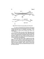
12.8 Vibration observed
at a
stationary
accelerometer.
There
is
simple explanation
in the
time domain
as
indicated
in
Fig.
12.8
which shows
the
vibration received
at the
accelerometer when there
are
three planets
and the
number
of
teeth
on the
annulus
is not
divisible
by
three
so
that
the
mesh phasing varies
by
120°
of
tooth frequency between
the
three
planets.
The
plot shows
two
cycles
of a
sine wave
at the
expected
frequency,
in
this example
12
times
per rev of the
planet
carrier,
in
phase
as the
1st
planet
is
near
the
detector.
For the
next
two
cycles
the
first
and 2nd
planet
are
equidistant
from the
accelerometer
so the
combined signal
will
have equal
amounts
of
in-phase
and
120°
phase
so
will
sum to 60°
phase.
The
next sixth
of
a rev
will
be
dominated
by the
vibration
from the 2nd
planet
and so
will
be
120°
phase.
Similarly
the
next sixth
will
average
2nd and 3rd
planet phases
and
so be at
180°
and the
next
at
240°
as the 3rd
planet dominates, while
the
final
sixth
will
average between 240°
and
360°
(or 0°) and so be at
300° phase.
The
next
rev
(not shown)
will
start back in-phase.
The
overall
effect
of
this
is
that although each section
of the
vibration
is
oscillating
at
exactly twelve
per rev of the
carrier,
the
phase
changes (technically
a
phase modulation) give
a
different
frequency.
Counting
up the
cycles shows that there
are 12 and
two-thirds
cycles
of
Planetary
and
Split
Drives
213
oscillation
in the
revolution
and as the
next sector vibration
will
be
exactly
back
in
phase
we
have gained
a foil
cycle. Frequency analysis
will
give
us 13
cycles
per
revolution instead
of the
expected
12 as if we had an
upper
sideband only.
The
above description assumed that
the
succeeding planets came
with
a
leading phase
but
equally well
the
planets could come with
a
lagging
phase
so
that
we
would lose
one
cycle
in
each
rev of the
carrier
and
observe
only
11
cycles
per
rev. Which
frequency we get
depends
on
whether there
is
1
less
or 1
more tooth than
the
exact divisible
by
three
number.
With
five
planets, similar arguments apply
and we can
observe
a
"sideband"
with
1
more
or 1
less cycle than
the
"correct" value. There
is
however
the
possibility
of
having
two
more
or two
less teeth than exactly
divisible
by five and we
would then
get the
result
of
apparently
a
single
frequency
at
two
cycles more
or
less
per
carrier
rev
than
the
expected
frequency.
The frequency
obtained when carrying
out a frequency
analysis with
a
large gear
will
depend
on the
length
of
time
of the
sample since
a
short
sample
may
effectively
be from one
planet
only
and so may be at
tooth
frequency
while
a
long sample
from a foil rev
will
be as
described above
Reference
McFadden,
P.D.
and
Smith, J.D.,
'An
Explanation
for the
Asymmetry
of
the
Modulation Sidebands about Tooth Meshing Frequency
in
Epicyclic
Gear
Vibration',
Proc.
Inst.
Mech.
Eng., 1985, Vol. 199,
No.
Cl,pp
65-70.
High
Contact
Ratio
Gears
13.1 Reasons
for
interest
We
normally
define
the
"geometrical"
contact ratio between
a
pair
of
gears
as the
length
of
line
of
contact, measured along
the
pressure line,
from
pinion
tip to
wheel tip, divided
by the
distance between
two
successive teeth
surfaces
also measured along
the
pressure line, i.e.,
the
base pitch.
From
a
glance
at
Figs.
2.7 and 2.8 it is
obvious that contact normally
does
not go
anywhere near
the tip of
either tooth
and
that real contact ratios
are
much lower than nominal contact ratios.
At low
loads
in
particular, there
is
only
one
pair
of
teeth
in
contact. More typically, under load,
a
nominal
contact ratio
of 1.7
might give double contact
for
only
15% of the
time
instead
of the
expected
40%
(0.7/1.7).
With
conventional proportion teeth neither
"short"
nor
"long"
relief
can
give
low
T.E.
at
both high
and low
load,
but if we can get the
true contact
ratio
up to
about 2.0, then
it is
possible
to
have quiet running
at
high
and low
loads.
It is not
possible
to get a
nominal contact ratio above
2.0
(and hence
a
true contact
ratio
of
about
2)
because
the
original standard tooth proportions
and
pressure angle were chosen rather arbitrarily
a
century
ago
well
before
gear meshing
was
investigated
and an
understanding gained
[1].
wheel
tip
limit
pressure
line
pitch
rack
tip
limit
Fig
13.1 Length
of
contact line with large tooth numbers
or
rack.
215
216
Chapter
13
Fig.
13.1
shows
the
limiting
case
for
standard teeth when
a
very
large gear mates with another large gear
or a
rack.
A
pressure angle
of 20°
and
an
addendum equal
to the
module gives
the
maximum length
of
approach
and
recess
as
m
cosec
<j)
and as the
base pitch
is m
n
cos
<j)
the
limiting
ratio
is
0.99
so the
contact ratio cannot exceed 1.98.
The
idea behind
high
contact ratio gears
is
that
for
high (design)
loads
we can
apply
the
standard Harris
map
approach
as in
Chapter
2 and
design
the tip
reliefs
so
that
the
elastic deflections
at
changeover
are
compensated
by the
shape
of the
relief.
At low
loads
the
contact
cannot
"drop" into
the
shape
left
by the tip
reliefs
as
there
is a
third pair
of
teeth
in
the
middle
of
their contact roughly
at
their pitch point
and so
maintaining
the
contact
on the
pure involute.
At the
changeover under load there
are two
pairs
of
teeth each taking half
of the
design force
and the
intermediate pair
of
teeth
is
taking
the
full
design force, which
is
half
of the
total contact load
directed along
the
pressure line.
We
thus have
the
possibility
of
very
low
T.E.
at
design load
and at
very
low
load with
a
relatively
low
T.E.
at
intermediate loads compared with
standard spur gears.
13.2 Design with Harris maps
Fig.
13.2 demonstrates
the
principle;
successive
teeth have been
staggered slightly
(a
pitch error)
for
clarity.
At low
load there
is
always
one
mating pair
of
teeth
on the
"pure
involute"
so
there
is
zero T.E.
At
high load
there
is
"long
relief
to
give
a
smooth changeover
from one
pair
to the
pair
two
teeth behind.
The
relief
is, in
practice,
a
rather small part
of the
profile.
Since
we
have
to
achieve
two
base pitches
from
changeover
to
changeover
and
allow
for
errors,
etc.,
the
nominal contact ratio must
be
above
2.0 and in
practice
about 2.25 minimum.
pure
no
load T.E.
for one
involute pair
\
-
\
pair
1
pair
2
pair
3
pair
4
deflected
position
under
full
load
Fig
13.2 Geometry
of tip
relief
and
deflections
for
contact ratio
of 2.
High Contact Ratio Gears
217
As
with standard gears
the
amount
of tip
relief
at the
tips must allow
for
elastic deflections under maximum loads, pitch
errors,
profile
errors
and
increased deflections
due to
overloads
or
misalignments.
The
amount
of
relief
at the
changeover points should
be
governed solely
by the
average
expected
elastic
deflection when there
are two
pairs
of
teeth
in
contact (away
from the
changeover)
and
should
be
half this value.
This type
of
spur gear design
will
give
low
noise under
a
range
of
loads
and is
reasonably insensitive
to
alignment errors though
it
requires
accurate manufacture.
The
ideas behind designing very quiet spur teeth
by
achieving
a
real
contact ratio
of 2.0
have been understood
in
principle since
the
detailed
dynamic
work
(by
Gregory, Harris
and
Munro)
was
published more than
40
years ago,
and in
industry work
was
done
as
long
ago as
1949
at
Wright Aero
[see chronology
in
Ref.
2].
Some
20
years later Boeing pursued
the
concepts,
but
it was
only recently that Munro
and his
student
Yildirim
at
Huddersfield
[3,4]
succeeded
in
measuring
the
actual unloaded
and
loaded T.E., quasi-
statically
and
dynamically
for
extremely accurately manufactured gears,
together with
the
corresponding vibration levels,
to
show that they
are
exceptionally
quiet
even
by
modern standards.
13.3
Two-stage
relief
Another slight modification
to the
philosophy involving high contact
ratio
and a
two-stage
tip
relief can,
in
theory, give zero T.E.
at not
only
full
load
but
also
at an
intermediate load. Work
by
Munro
and
Yildirim
investigated this possibility.
There
is a
corresponding disadvantage
in
that there
is
some T.E.
at
zero load
and
there
is a
stressing
penalty involved.
Another variant uses
a
two-stage
relief
to
ease
one of the
manufacturing
problems that
can
occur with
the
design shown
in
Fig.
13.2.
The
problem arises because
the tip
relief design
has to
give perhaps
50 um of
tip
relief
in a
short roll distance.
If the
base
pitch
of the
gear
is of the
order
of
10
mm
there
is
only about
1 mm of
roll distance
in
which
to
move
the 50 um
and
so a
sudden change
of
direction
is
needed
at the
join
between pure involute
and tip
relief.
Some manufacturing
processes
which generate
the
profile
cannot deal
with
this sudden
a
direction change
so the
design
has to be
altered.
A
possible
solution
is
indicated
in
Fig. 13.3 which shows
the
changeover area between
two
pairs
of
teeth.
The
dashed lines
are the
basic
tip
relief shape
and
involve
a
sharp change
of
direction
of
relief
at the
points labelled
E,
which
are the
ends
of
the
pure involute sections.
218
Chapter
13
crossover
position
1st
mesh
L
3rd
mesh
deflected
position
under
design
load
Tip
Fig
13.3 Sketch
of
basic
tip
relief design
and
modified
shape.
As
previously, there
is no
T.E.
at
light load because
the
intermediate
pair
of
meshing teeth
are in the
middle
of
their involute section.
It is not
possible
to
alter
the
amounts
of the tip
reliefs
or to
alter
the
deflection
at the
crossover point
C so
these points remain
fixed.
The
modification
to
ease manufacturing
is to
start
the tip
reliefs
at the
points
labelled
L,
roughly
1.5
times
as far as the E
points
from the
crossover.
The tip
relief then increases
at
about two-thirds
the
previous rate until
the M
points
are
reached
at
full
depth
of the
expected deflected position.
The tip
relief then continues
to the fixed tip
position.
The
angle change (formerly
at
E)
is
reduced
to
two-thirds
of
previous
and
there
is a
comparable angle change
at M
which
is
also
two-thirds
of the
previous
E
angle. Although
two
angle
changes
are now
involved,
the
second
one at M is in a
less critical part
of the
relief
and so
errors
of
shape
are
unimportant.
13.4
Comparisons
To get
2.2+ nominal contact ratio
we
need taller, thinner teeth
and the
pressure
angle must come down
to
below
16°
with large numbers
of
teeth,
or
the
teeth
must
be
taller, again pushing
up the
minimum number
of
teeth
to
prevent pointed teeth. This means
in
general more teeth, which involves using
a
lower module. There
is
thus
a
double root
stressing
penalty
as
there
is a
High Contact Ratio Gears
219
stressing penalty associated with slender teeth
and the
penalty associated with
finer
teeth. Contact
stresses
are
relatively
unaffected
as
they depend primarily
on
diameter rather than module. There
is a
stressing
bonus
from
always
(in
theory) having
two
pairs
of
teeth
in
contact
but
this depends
on
having
accurate manufacture
and
very
low
adjacent pitch errors.
The
other
factor
which
is
affected
by the use of
high contact ratios
is
the
contact
flexibility of the
mesh
as
tall slender teeth greatly reduce
the
mesh
stiffness.
This
will
have
a
negligible
effect
on the
lower resonance
frequencies
of
a
drive system
but
will reduce
the frequencies of
those vibration modes
which
are
controlled
by
tooth
stiffness.
These
frequencies are
usually
well
above
the
working range
for
most gears.
The
question
is
sometimes asked
as to
whether
it is
better
to go to
high
contact ratio (spur) gears
or to
helicals
if
noise
is
very critical. There
is
no
standard answer because
the
main
factor
controlling helical gear noise
is
the
accuracy
of
alignment, assuming well designed gears. This
is
very
difficult
to
control despite
its
dominating
effect
on
both noise
and
stresses.
The
"best" answer
in a
critical case
is to be
pessimistic
and
assume
there
will
be
some alignment errors
and to
make
the
drive helical with
a
high
(>2.0) contact ratio.
As
always, design
is a
trade-off
between noise
and
stress.
13.5
Measurement
of
T.E.
For
conventional gears measurement
of
T.E.
in the
metrology lab.
is
straightforward
as we
mount them
at the
correct centre distance. Although
we
only
see the
zero load T.E.
as in
Fig.
2.7 the
shape tells
us the
important
information
which
is how
large
the
T.E.
dip is at the
changeover point
and
whether
the tip
relief
has
started
the
correct roll distance
from the
pitch point.
If
these
are
correct
we can
reasonably
infer
that
the
part
of the
involutes
we
cannot
see
(dashed)
is
probably good enough.
High
contact ratio gears immediately present
a
problem since
if we
mount
them
at the
correct design centre distance then under
no
load
we
should
get
zero T.E. right through
the
meshing cycle
so we
cannot
see if the
crossover
under load
will
be
correct.
As the
starting position
of the tip
relief
is
important
to
ensure correct deflection
at
crossover,
we
need
a
test
which
can
measure
the
amount
of tip
relief without being masked
by the
meshing pair in-between
holding
the
pure involute.
An
answer
to
this masking problem
is to
increase
the
centre distance
greatly
so
that instead
of a
contact ratio slightly over
2 we
have
a
contact ratio
slightly
over
1.
This depends
on the
tolerant properties
of the
involute
and is
only
relevant
for
well designed
and
manufactured
gears
where most
of the
profile
follows
a
pure involute. Because
the
centres have been moved apart,
the
length
of
"pure" involute
has
been roughly halved.