Gear Noise and Vibration Episode 2 Part 7 potx
Bạn đang xem bản rút gọn của tài liệu. Xem và tải ngay bản đầy đủ của tài liệu tại đây (919.38 KB, 20 trang )
260
Chapter
16
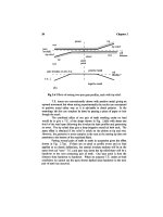
Fig
16.12 Sketch
of
vibration responses
and
paths.
In
practice, because measuring inside
the
gearbox
is
very
difficult,
it
is
probably better
to
rely
on
T.E. excitation when running
or to
estimate
the
internal resonances.
The
reciprocal theorem
is of
limited help since, although
it
may
help
for
cross
receptances
P
13
and
p
2
3,
it
does
not
assist
access
for
Pj
2
or the
local responses
Pn
and
P
2
2
which need access inside
the box in
zero
space.
In
some cases
the
wheel
is so
massive
and its
support
is so
stiff
that
wheel response
may be
ignored, simplifying
the
algebra considerably.
16.7 Coherence
Whichever method (b),
(c) or (d) is
used
for
measuring
a
transfer
function
with
a
transfer
function
analyser,
it is
worthwhile checking coherence
if
there
is any
possibility
of
background noise, whether mechanical
or
electrical.
The
idea
of
coherence
is
that
if we
take
a
single transfer
function
measurement
we can
deduce
a
transfer function. However,
we do not
know
how
much
of the
output
is
really
due to the
input
and how
much
is due to
random external
(or
internal) disturbances.
Repeating
the
test many times
and
getting exactly
the
same result
in
both amplitude
and
phase would suggest that there
is
little random
effect.
Any
variation would suggest randomness. Coherence analysis routines carry
out
this check
and
compare
how
much
of the
measured output power
(at a
Vibration
Testing
261
particular
frequency) can be
attributed
to the
consistent
transfer
function.
A
coherence
of 1
suggests that output
is
firmly
connected
to
input
but < 0.5
suggests that random noise
is
dominating
the
measurements.
Any
results with
coherence
< 0.8
should
be
viewed with suspicion.
Even
if
there
are two
vibrations
whose coherence
is 1 it is not
necessarily true
to say
that
the
output
is
"due
to" the
input since both vibrations
may
have been generated
by
another
unknown
input.
In
particular
a
panel vibration
may not be
caused
by the
vibration
at a
bearing housing because both
may
have been caused
by
vibration
from
another bearing
or
even
from a
separate slave drive.
To
carry
out a
coherence check
it is
necessary
to
take multiple
tests,
typically eight.
It is not
possible
to get a
meaningful
result
from a
single test because
it is
necessary
to
check whether
the
result
is
consistent over time.
Extra care should
be
taken when impact testing because even though
the
responses
may be
consistent
from
test
to
test there
is a
greater likelihood
of
non-linearity. This
in
turn will lead
to
false
deductions
since
a
high
response
at
one frequency may in
fact
be due to
excitation
at,
say, one-third
of the
frequency
encountering
a
non-linearity.
Couplings
17.1
Advantages
Couplings
in a
system
are
rarely
fitted
initially with
a
thought
to
their
effect
on
noise.
The
most common requirement
is
that
the
coupling must
accommodate
misalignments which
may be due to
manufacturing
or
assembly
errors
but are
often
due to the
effects
of
differential
thermal growth, which
can
be
surprisingly large.
A
temperature
difference
of
40°C
can
easily occur
between
a
turbine
casing
and a
gearbox
and if the
centre height
is 1
m
the
corresponding
differential
expansion
is 0.4 mm (16
mil). Axial growth
can
also present problems since
a
motor gearbox combination
in a
medium-sized
(400
kW)
installation with
a
distance
of 4 m
between
foundation
attachment
points
and a
temperature
rise
of
50°C
can
expand axially
by 2 mm.
As
far as
noise
is
concerned,
the use of a
coupling
is
usually
advantageous since those couplings which
use
rubber blocks
as the
torque
transmitting units have
flexibility for
both torsional
and
lateral vibrations.
The
steel diaphragm type
of
coupling, usually used
in
pairs with
a
short torque
shaft
in
between,
is
torsionally
stiff
but
laterally
flexible.
Toothed gear couplings
are
short
and
light
and
have lateral
flexibility
and,
in
theory, axial
flexiblity but
like diaphragm couplings have high
torsional
stiffness.
In
most
installations
the
transmission
of
gear noise along
the
input
or
output
shafts
is not
important
as
there
is
likely
to be a
large inertia
for
load
or
driver
and so
vibrations
will
be
absorbed
by the
inertia. Typically this occurs
on
a car
where
any
torsional vibrations
from the
gearbox encounter either
the
high inertia
of the
engine
or of the
wheels.
In
the
case
of the
wheels there
is
also
the filtering
effect
of the
propshaft
flexibility to
attenuate vibration.
The
exceptions
to
this occur when there
is a
large
propeller
or
turbine
which
can act as a
very
effective
radiator
of
noise.
On
naval ships
the
propeller
has a
large surface
and the
vibration
frequencies are
high
so
that
any
vibration will radiate
powerfully
and
betray
the
ships
position.
Under
these
circumstances
it is
critical
that some
form
of
very
flexible
coupling
is
used
for
isolation
of
both lateral
and
axial vibration.
A
similar requirement occurred recently with
the
installation
of
wind
turbines
for
"renewable energy" purposes. Early designs
did not
consider that
263
264
Chapter
17
noise
would
be a
problem
as the
installations were meant
to be
away
from
dwelling
houses. They made
the
mistake
of
connecting
the
propellor directly
to a
gearbox which
was
chosen
for low
cost rather than
low
vibration.
The
result
was
that
the
relatively large vibrations
at
1/tooth
and
harmonics were
transmitted straight through
to the
propellor. This acted
as a
remarkably
efficient
loudspeaker with
a
very large surface area
and
produced
a
gear whine
which
could
be
heard miles away.
The
eventual solution
was not
only
to use
high quality gears
and
reduce propellor dynamic
flexibility but to
isolate
the
propellor
from the
gearbox
with
a
soft
rubber torsional coupling.
In
addition,
of
course,
the
gearcase
had to be
effectively
isolated
from the
supporting tower
which
could also
act as a
noise radiator.
At the
other
end of the
drive there
was no
problem
as the
high inertia
of the
generator absorbed
all
vibration very
effectively.
17.2 Problems
The
problems associated with rubber couplings
are
usually
at low
frequencies
where either
the
torsional
flexibility
of the
coupling gives
a
torsional
resonance
at a frequency too
near
the
running speed
or the
mass
of
the
coupling brings whirl speeds down into
the
operating range. This
effect
on
whirl
speed
can of
course also occur with
diapraghm
couplings.
It
is
difficult
to
carry
out
accurate predictions
because
the
properties
of
rubber couplings
are not
well documented. This
is
partly
due to
production
variations
which give
a
surprising spread
of
rubber hardness which
can
vary
some
± 20% so
that
it is
possible
to find a
"soft"
unit which
is
stiffer
than
a
"hard" unit
of the
same
design,
hi
addition
the
characteristics
of the filled
natural
rubber which
is
usually used vary
at low
amplitudes both
in the
stiffness
and the
damping factor
as
well
as
varying with
frequency.
Typically
dynamic
stiffness
may be 40%
higher than
the figures
quoted
by the
manufacturer
(as
they
are
given
for low frequency
response).
Reliable information
can be
obtained
by
using
a
back-to-back
rig to
give
an
exact replica
of
operating conditions
as
indicated
in
Fig.
17.1.
High
drive
torque
is
applied statically, then
the
intermediate ring
is
oscillated
torsionally
at the
correct (low) level using
two
opposed
exciters
mounted
tangentially
and is
measured using
two
tangential accelerometers.
It
is
necessary
to
mass
correct
for the
moment
of
inertia
of the
intermediate ring.
Torsional couplings, like conventional vibration isolators,
may
also
have been designed
and
installed with
the
main objective being
to
isolate I/rev
and
2/rev vibration
and so may be
ineffective
for the
much
higher
frequencies
of
gear
noise.
Couplings
265
I
sandwich
plate
coupling
;
coupling
w,.
torque
arm
accelerometer
sandwich plate
I
accelerometer
Fig
17.1
Back-to-back
test
rig for
torsional
stiffness
under working torque.
The
high static torque
is
applied
by the
torque arm, which
is
then locked.
266
Chapter
17
reverse
drive block
working
block
reverse
drive block
Fig
17.2 Sketch
of
axial
view
of
coupling with axes
offset.
17.3
Vibration generation
Couplings
are
capable
of
producing unexpected results
by
injecting
torsional excitation
or
modulating existing gear noise.
The
most common problem occurs when
a
simple rubber block
coupling
is
used
to
connect
two
shafts
which
are
slightly
offset.
The
effect
is
shown
diagrammatically
in
Fig.
17.2.
If
there
are
four
rubber blocks
the
load should
be
taken
by two of the
blocks
in
each direction.
With
offset,
the
load
is not
taken evenly
by the two
blocks
and
with hard rubber
or low
loads,
one of the
blocks takes
all the
torque
and
there
is
clearance
on the
other block
for
half
of the rev
then
the
other block
drives
for the
other half
of the
rev.
The
resulting
error
is as
shown
in
Fig.
17.3
and
with
an
amplitude
peak-to-peak
equal
to the
offset
acting
at
block radius.
Alternatively
manufacturing
tolerances
can
give once
per rev
errors.
Couplings
267
1
revolution
Fig
17.3 Torsional transmission error
with
offset.
Assembly
of a
drive motor onto
a
worm
and
wheel gearbox with
conventional tolerances
can
easily involve
an
offset
and
runout
of
100
jam
and
this
can
appear
as
either
a
I/rev
or
2/rev
effect
according
to the
type
of
error.
Any
attempt
to
measure T.E. under
these
circumstances will give
(at
1/tooth
or
2/tooth)
an
apparent gear error
of the
order
of the
offset
and so
possibly
a
factor
of
10
larger than
the
true
gear
errors.
This
effect
can
occur
to
a
limited extent with higher numbers
of
blocks
but
will
be
small
if all the
blocks
are
under
sufficient
load
to be in
contact
all the
time
so
that
the
system
remains linear.
Diaphragm couplings
are
preferably radially symmetric
and so
will
not
inject torsional vibrations into
a
drive
but the
trailing link type
of
coupling
needs
to
have more than
two
links
to be
self centering
and so to be
satisfactory
when
used
at
each
end of a
torque
shaft.
Gear tooth couplings
can
produce some very unexpected results. They
are
radially symmetric
and so we
would expect
a
smooth drive with
no
injection
of
extra
frequencies.
They
will
in
practice
run
vibration
free
when
they
are
perfectly aligned
and
also when they
are
badly misaligned.
Vibration
problems
can
arise
when they
are
only slightly misaligned.
In
a
gear tooth coupling there
are friction
forces
as
sketched
in
Fig.
17.4
and
there will also
be
some bending elasticity
in the
drive
shafts.
There
are two
extreme
cases.
268
Chapter
17
Fig
17.4 Sketch
of
gear tooth coupling. Friction forces
are
controlled
by
axial
velocity
and
thus generate
a
couple
to
bend
the
drive
shafts
out of the
page.
Near perfect alignment allows
the
coupling
to
lock
up as the friction is
sufficient
to
bend
the
shafts
so
that there
is no
relative axial motion
at the
meshing gear teeth
and
there
is no
vibration excitation apart
from a
I/rev
bending
on the
shafts.
Significant
misalignment gives continuous sliding
at
the
coupling gear teeth
and
thus
no
significant vibration injection.
The
problem arises with small misalignments which
will
initially
bend
the
drive
shafts
because
there
is not
sufficient
force
to
overcome
the
axial
friction at the
teeth
but
after
perhaps one-third
of a
revolution
the friction
will
be
overcome
and
there
will
be an
axial slip
at the
teeth. This
effect
will
inject
a
disturbance
into
the
drive
at
3/rev, altering
the
shaft
bending
at
this
frequency and so
disturbing
any
neighbouring gear mesh
at
this
frequency.
This
can
lead
to the
modulation
of the
gear noise
frequency so
that noise occurs
at
tooth
frequency
plus
or
minus 3/rev. Deliberate alteration
of the
misalignment
may
change
the
slip
frequency
higher
or
lower
or it may
disappear completely.
As
far as
testing T.E.
is
concerned
it is
much
safer
to
test
the
gear
drive separately without
any
couplings
in
place
to get the
basic gear
information
then,
if the
couplings
are
suspect,
to
test
the
complete assembly.
Unfortunately
this must
be
done under load
as
otherwise
the friction
forces will
not
be
correct.
18
Failures
18.1
Introduction
Although
this book
is
predominantly about gear
noise,
it is of
interest
to
discuss
the
various
failure
mechanisms
to see
which might
be
connected
to
noise
and
which
are
not.
As may be
deduced
from the
comments
in
Chapter
15,
there
is in
general
not
much connection.
18.2
Pitting
Pitting
arises
from
traditional
Hertzian
contact
stresses
giving failure
as a
result
of a
fatigue
process.
The
standard theory
[1]
gives
the
results that
for
line
contact,
i.e., cylinder
to
cylinder with load P'/unit length,
the
maximum
contact pressure
p
0
,
and the
semi contact width
b,
will
be
1
_ 1 1
Effective
curvature
~R~~R~
+
~R~
where
Rj
and
R.2
are the
radii
of
curvature.
1
_
l
~
v
l
1
~
V
Contact modulus
~
p
+
~~£
E
1 2
moduli
and
Poisson's ratio,
and
suffixes
1, 2
refer
to the two
bodies
in
contact.
The
maximum shear
stress
is
then
t
m
ax
=
0.300
p
o
at x = 0, z =
0.79b
This leads
to a
maximum shear
stress
occuring
typically about
0.5 mm
below
the
surface
and
giving fatigue cracks which,
for
traditional pitting, travel
initially horizontally then curve upward toward
the
surface. When they reach
the
surface
a
hemisphere
of
steel breaks
out
leaving
the
classical
pit
which
is
typically
1 mm
diameter
and 0.5 mm
deep.
269
270
Chapter
18
tip
oo
o
5
root
Fig
18.1
View
of
tooth
flank
with
pitting.
The
simple static theory suggests that pitting
will
be at its
worst where
stresses
are
highest because
the
effective
radius
of
curvature
is
smallest, which
is
when
contact
is
toward
the
root
of the
pinion
but
this
is not
what happens.
The
pitting occurs initially very near
but not
exactly
on the
pitch line where sliding
velocities
are low and the
typical pattern
is
sketched
in
Fig.
18.1.
In
cases
where
a
gear pair
is
significantly
misaligned
the
pitting will concentrate
on the
highly
loaded areas.
The
result
is an
area
of
metal removal which
is
sometimes called
spalling
[2].
Whether
the
term spalling should
be
used
for
this localised heavy
pitting
is
debatable
as it was
formerly used
for the
rather
different
failure
when
the
"skin"
of an
inadequately
carburised
gear
peels
off, giving
an
effect
labelled
as
case/core
separation
in the
AGMA
1010.
The
flake
pitting [2], which
is
sometimes
encountered,
is
similar
and may
also
be
caused
by
faulty
carburising.
Pitting depends
on
fatigue
and so is a
relatively slow process which
in
most
cases stabilises. Occasionally
the
loadings
are too
high
for the
material
and
the
pitting
progresses
and
covers
the
whole gear surface
but
even this serious
deterioration
is
unlikely
to
produce "gear" noise because
as
mentioned
in
Chapter
15
the
frequencies
are
very high
and
tend
to be
reflected
or to be
absorbed before
reaching panels which could radiate noise.
18.3
Micropitting
Micropitting
(sometimes called gray staining)
has
become more
important recently, possibly
as a
result
of
greater
use of
case-hardened gears
and
changes
in
manufacturing techniques.
It has
similarities
to
conventional
pitting
but
occurs
on a
much smaller distance scale
and
occurs
at
slightly lower
loads
than pitting.
Unlike
conventional pitting,
it
tends
to
spread
and
progress
and may
start anywhere
on the flank.
Failures
271
The
initiation
is due to
asperity contacts generating local high
stresses
with
friction
forces
assisting
the
process.
It
differs
from
pitting
in
that because
asperities
are
small, with
sizes
of the
order
of
jim,
the
stress
fields
are
very
localised
so the
pits generated
are
comparable
in
size with
the
surface
finish
rather than
the
mm-sized
stress
fields of
pitting.
20
|jjn
is a
typical depth
of a
micropit
[2].
A
prime requirement
for
micropitting
to
occur
is
that
the
asperity
heights
are of the
order
of, or
greater than,
the oil film
thickness which
is
typically
1
jirn
or
slightly less.
The use of
synthetic oils
at
high temperatures
has
tended
to
reduce
oil film
thicknesses
and so
increases
the
likelihood
of
micropitting.
As far as
noise
is
concerned,
the
comments that apply
to
pitting
are
even more relevant.
The
scale
of the
micropits
is so
small that
at
normal
running
speeds
the frequency of the
pits
is
above
the
normal audible range
so
that
even
if the
vibrations were transmitted they could
not be
heard.
In
practice they
do not
transmit
out
through
the
bearings.
There
is
currently considerable interest
in
micropitting
but
tests
carried
out as
long
ago as
1987
[3]
indicated that using
a
mirror
finish so
that
the
surface roughness (about
0.1
\un)
was
less
than
the
lubrication
film
thickness (0.4
um)
gave increased resistance
to
micropitting. This would then
raise possible operating conditions
to the
normal pitting limit
as
dictated
by
Hertzian contact
stresses.
It is
unfortunate that
the
standard grinding
processes
tend
to
leave
a
rather rough surface
finish
which encourages micropitting.
18.4 Cracking
Traditionally
cracking
occurrs
at the
tooth root
as
sketched
in
Fig.
18.2.
The
crack starts
at a
surface stress raiser somewhere
in the
tooth root,
well
away
from the
working
flank
and
once started
it
spreads rapidly
so
that
the
complete section
of
tooth
falls
out.
On a
helical gear
it is not
usual
for a
complete tooth
to
fail
but
perhaps
one-third
of the
width
of the
tooth
may
crack
off.
This
form
of
failure
is
very rare
since
it is
liable
to be
rapid
and
disastrous. Because
it is so
serious, normally design
carefully
avoids
it and the
flank
pitting should occur
first.
Tooth root cracking
is
usually
an
indication
of
faulty
design
or
faulty
heat treatment.
The
surprising feature
is
that tooth breakage
can
occur
and may not be
noticed until
a
routine
stripdown
uncovers
it.
Noise generation
is
usually
not
noticeable
and
even monitoring equipment
may
miss
it. The
major
hazard
is if
the
broken tooth attempts
to go
through
the
mesh
and
jams
the
drive.
272
Chapter
18
tip
Fig
18.2 Crack positions.
Cracking
can
also give trouble starting
in the
middle
of the
working
flank,
often
near
the
pitch line.
The
initiation
in
this
case
appears
to be due to
the
cracks which (macro) pitting
and
micropitting
generate
and
which
may
branch downward into
the
main body
of the
tooth instead
of
branching
upwards
to
give
a
pit. Friction
at the
contact appears
to
play
a
significant part
and
this,
in
turn,
is
very dependant
on the
lubrication conditions.
As
with
conventional root cracking
there
is
likely
to be
little
or no
noise
generation.
18.5
Scuffing
Scuffing
involves breakdown
of the oil film so
that
metal-to-metal
contact
can
give welding
and
subsequent tearing
and flow of the
surfaces.
It
may
be
associated with
too
thin
an oil or
excessive loading
or
large sliding
velocities giving
too
much heat input
to the
oil.
The
curiosity
in
relation
to
scuffing
is
that
the
process
is
very similar
to
running
in of
gears. Both
are
associated
with asperity
contacts
which result
in
metal removal
and the
main difference
is one of
scale.
Running
in
removes
the
(small) asperities
and the
surfaces become smoother whereas with
scuffing
the
scale
is
larger
and
welding
occurs
so the
surface dragging gives rougher
surfaces.
The
borderline between
the two
processes
is not
clearly defined
and
can
only
be
followed
experimentally
by
monitoring with Smith shocks
[4].
A
downward trend
of the
shock level indicates successful running
in
whereas
an
upward trend shows
scuffing
and the
conditions should
be
altered immediately.
Failures
273
When
the
scuffing
is due to
lack
of
lubrication
it is
possible
not
only
to
halt
the
damage
by
restoring lubrication
but to
improve
the
surfaces
to
restore
their
full
load
carrying capacity.
On
some slow
but
very heavily loaded gears
the use of
a
good grease
can
heal surfaces that have previously been damaged
by
cold
scuffing.
As
far as
noise
is
concerned
the
initial
stages
of
scuffing
are
very
irregular
and
local
to a
single point
in a
gear
so
that there
is not a
regular
pattern
linked
to
1/tooth
or
other expected
frequencies in the
audible range.
The
I/rev impulses that
are
generated
are
short
and so
should give
a
noise
similar
to a
burr
or
isolated damage
on a
tooth. Once there
is a
significant
scuff
the
vibration
can be
detected
by
conventional
accelerometer
monitoring
but
the
deterioration
may be
very
fast
by
that
stage.
18.6
Bearings
The
normal pattern
of
design
for
gearbox bearings
has
been that only
very
high power gearboxes needed
to use
hydrodynamic
bearings
with
their
cost
and
complications
of
high
oil flow
rates needing hundreds
of
horsepower
to
achieve
the
cooling
rates
required. Hydrodynamic bearings might
be
needed
simply
because speeds were
too
high
or
because specific loadings were
too
high
for
rolling bearings.
Medium-sized
gearboxes
are now
encountering loading limitations
increasingly
due to
improvements
in
gear loadings
and to the
basic scaling
laws
for
gears
and
rolling bearings.
As a
very rough rule
the
load
on a
gear
may
be
increased proportional
to
size squared whereas
the
load
on a
bearing
may
increase less rapidly.
If we
take
figures for the
"heavy duty bearing",
a
spherical
roller bearing, then within
an O.D of 190 mm we get a C
rating
of
535 kN and an
infinite
life
rating
of 67
kN.
Doubling
the
O.D.
to 380 mm
allows
a C
rating
of
1730
kN and an
infinite
life
of 193 kN.
This seems
to
follow
a
rough rule that doubling
the
size
increases
capacity
by a
factor
of
three
whereas
on a
gear
we
would
expect
an
increase
by a
factor
of
four.
The
corresponding gear size
may be
estimated very roughly
by
using
the
100
N/mm/m rule.
20
teeth
of 20 mm
module
with
a
"square" pinion gives
a
load
of 100 x 20 x 400
which
is 800 kN. For any
long
life
installation such
as a
chemical works
or
sewage plant
it is
advisable
to use the
infinite
life
value
so we find
that
a
bearing
of
slightly less than
the
size
of the
pinion
will
only
take
one
quarter
of the
gear load.
The
situation
is
slightly
eased
if the
pinion
support
is
symmetrical
but the two
bearings
can
only take half
the
possible gear
tooth
load. Taking
the
full
load symmetrically with
two
bearings requires
an
O.D.
of 460 mm and an
asymmetric design with
600 kN
load
on one
side
would
need
520 mm
O.D. There would
be
enough radial space
for
this with
a
large wheel
but not
with
a low
reduction ratio.
274
Chapter
18
The
effect
of
this
is to
force
the
designers
to use
lower safety margins
and
hence increase
the
possibility
of
rolling bearing failures.
It is
unlikely that
incipient
failure
of a
rolling bearing will give audible noise problems
but it is
fortunate
that this type
of
damage
can
usually
be
picked
up
effectively
by
bearing housing monitoring.
Use of
high loads makes bearings much more
susceptible
to
dirt
or
debris
as the oil
films
are
thinner
and the
extra stresses
due
to the
particles
are
imposed
on
stresses
which
are
already high.
Other problems that
may
give bearing
failure
stem
from
there being
insufficient
load
on a
bearing.
The
manufacturers give
empirical
rules
for
estimating
the
minimum load
at
high speeds
but
these
are for
steady speeds
only.
Heavy torsional vibration
of the
sort associated with light loads
and
inaccurate gears (rattle)
can
demand high torsional accelerations
of the
rolling
elements
and if
loads
are
light then skidding
of the
rollers
can
occur
and
damage
the
bearing rapidly.
One
heavy duty drive
was
unwisely tested under
no-load
and
failed
in a
couple
of
hours
but
would have operated
for
many years
under
full
load.
Multistage gearboxes with high reduction ratios present severe design
problems since there
may be,
say,
100
to 1
variation
in
speed
so the
ideal
oil
viscosity
for the
high speed gears
and
bearings
is
totally unsuitable
for the low
speed gears
and
bearings.
It is
advisable
to
bias
the
choice toward
the low
speed bearings
and
increase
the
viscosity even though this will increase
the
lubrication
losses
and
thus increase heat generation.
18.7
Debris
detection
Traditionally
debris detection
is one of the
oldest techniques
for
giving
indication
of
trouble. Magnetic plugs were
of
limited
use
since they
were usually only inspected when
an oil
change
was
scheduled. Modern
particle counting techniques
are
very
effective
to
give
an
accurate quantitative
assessment
of the
state
of the oil and
must
be
used
if
bearings
are
heavily
loaded
and so are
very vulnerable
to
dirt
or
debris
in the
oil.
The
results
of
debris analyses
are in the
form
of the
number
of
particles counted
in 100 ml of oil and the
figures
are
surprisingly high.
Several
versions
can be
used but,
for
gears
and
rolling bearings,
the two
figures
which
are
usually quoted (and
are of
most interest)
are for the
number
of
particles above
5
um
and the
number
of
particles above
15
um
respectively.
The
numbers
are not
given directly
but are
classified
on an
approximately
binary
scale.
A
brand
new
clean
oil
might
be
naively
expected
to be
particle
free
but
in
practice
may
have
a
test
count
of
200000
/
7000
and so
would
be
classified
as
18/13.
There
are
sometimes three figures quoted
but
then
the first
figure is for the
particle count over
2 urn and is not of
interest
for
gearboxes.
Failures
275
It
is of
interest
to
compare
the
test sizes
of 5 and
15
urn
with
the
expected
oil
film
thicknesses, which range
from
less than
1
um
in a
rolling
bearing
to 3 to 4
pun
in a
medium-sized
but
lightly loaded
gear.
The
particle counts
are
classified into groups according
to ISO
4406
and
the figures are
Particles
per
100
ml
500000
250000
130000
64000
32000
16000
8000
4000
2000
1000
500
250
130
64
32
to
to
to
to
to
to
to
to
to
to
to
to
to
to
to
1000000
500000
250000
130000
64000
32000
16000
8000
4000
2000
1000
500
250
130
64
Group
20
19
18
17
16
15
14
13
12
11
10
9
8
7
6
Bearing manufacturers typically suggest that 18/14
is a
"normal"
cleanliness
for oil and so the
above
new oil
would
be
"normal".
Unfortunately,
to be
able
to use
rolling
bearings
to
their
full
capacity
"normal" cleanliness
is
nowhere near good enough
and the
requirement
is to
achieve
much
better.
FAG
suggest that
14/11
is
needed
but
better cleanliness
is
needed
if the
contaminants
are
abrasive (such
as
sand). Work done
at SKF
[5]
suggests
that
for
rolling bearings, debris
of the
expected high hardness will
give
raceway damage when
the
particle size exceeds
5
um.
Below this size
it
appears that
the
elastic
deformations
of the
surfaces
can
accommodate
the
particles without reducing
the
life.
SKF
suggest that
for
absolute
maximum
life
the
contaminants should
be
comparable
in
size
to the oil film
thickness
but
this means there should
be
very little debris above
1 um.
INA
also state that
for
"extreme cleanliness" particle
sizes
should
be
less than
the film
thickness.
Normal
industrial practice
is to
have what
the
bearing manufacturers would
classify
as
typical
contamination
with
a
heavy
life
penalty.
There
is a
further
problem
for the
gearbox user
in
that there
is no
direct connection between
the
specification
for the filter and the
corresponding
particle count
in the
gearbox. Filters
are
specified
in
terms
of
their reduction
276
Chapter
18
ratio
for
particles
of a
given
size
so
that
a
(5
6
^75
as
suggested
by FAG
would
reduce particle count
for
those above
6
urn
by a
factor
of 75 for a
single
pass
through
the
filter.
Whether
a
recirculation
of the filtered oil
will reduce
the
count
by
another
factor
of 75 is not
discussed.
The
resulting contamination
in
the oil
depends
on how
fast
the oil is
being circulated through
the filter
and,
more importantly,
how
fast
fresh
contamination
is
entering
the
system
(possibly
from the
gears?).
In
practice
the
only reliable solution
is to
monitor
the oil
particle
content.
After
a fresh
batch
of oil (at
18/13)
is
added
to the
system
the
particle
count
should drop
to
14/11
or
preferably better
and
should stabilise.
Any
subsequent increase requires
a
change
of filter and
probably
a
check
on the
source
of the
debris.
Gear
contact
oil
films are
thicker than rolling bearing
films so
should
be
less susceptible
to
dirt
but as
gears have some sliding rather than pure
rolling motion there
can be
tendency
to
give scratching
on the
tooth
flanks.
This means that
it is
sometimes easier
to
detect
debris
in a
gearbox
by
looking
at
scratching
on the
gear
flanks
than
by
attempting
to see the
inaccessible
roller tracks where
any
debris damage
will
be at a
point instead
of
producing
a
scratch.
When
there
are
thick
oilfilms
as
with plain bearings
or the
rolling
bearings
are
lightly loaded
it is not the
bearing which
is the
critical member
and
a
build
up of
debris
will
show
up as
abrasive wear
on the
tooth
flanks.
This
is
especially
so
with spiral bevel gears which have high sliding velocities
and
so are
very vulnerable
to
dirt.
Looking
at the
various
failure
mechanisms
and
their
likely
eifect
on
oil
debris
is not
encouraging. Tooth root cracking produces
one
large lump
which
with luck
will
drop
to the
bottom
of the
gearcase
and not
move
so
there
will
be no
indication
of
trouble
from
debris analysis whether chemical
or
particle counting. Pitting (macro) again produces
a few
relatively large
hemispheres which
will
not
show
up in a
particle count
and
will usually stay
at
the
bottom
of the oil
tank
or
sump.
Scuffing
should produce some
fine
debris
and so
should
be
detectable
but
only
micropitting
would produce large
quantities
of
relatively
fine
debris particles.
The
conclusion
is
that surface wear (due
to
debris)
or
micropitting
will
put up
particle counts
but
that
the
other
failure
mechanisms will have little
effect.
Any
connection between
debris
and
noise
is
unlikely
as
normal debris
is
small
so
gives pulses which
are at too
high
a frequency to
hear
and
which
occur intermittently.
As
mentioned previously
in
Chapter
15,
the
most sensitive debris
detection system
yet
encountered
for
small
particles
is
using Smith shocks
to
detect
the
particles passing through
the
mesh
but
this
is too
sensitive
for use in
Failures
277
normal
commercial gearboxes
and is
unlikely
to be
used
due to the
experimental complications involved.
18.8 Couplings
Couplings appear
to be an
unimportant part
of the
system
but can not
only
occasionally themselves
fail
but can
produce
failures
in
other parts
of the
drive.
Design
for the
steel
diaphragm
type
of
coupling
is
straightforward
as
the
coupling stiffnesses, axially
and in
bending, should
be
given
in the
sales
literature
and so it is
easy
to
predict what loadings
will
be
applied
to the
shafts
on
either side. Axial loadings need
to
allow
not
only
for
assembly errors
but
also
for
thermal
differential
expansions.
The
rubber block type
of
coupling
is
much used
in
small drives
as it
can
accommodate some
offset
of
axes
as
well
as
angular misalignment
so
only
one
coupling
is
needed instead
of two
with
the
diaphragm type.
The
corresponding disadvantage
is
that although
the
blocks
deform
to
take
the
offset
there
is a
significant sideways
force
which
may
fatigue
shafts
in
bending.
A
rather unusual problem
can
arise
due to
thermal
effects
if the
axial growth
is
sufficient
to
take
up the
clearance
in the
coupling.
The
metal
(or
plastic)
castings
can
then meet
and
impose severe axial forces
to
produce
failure
of
motor
or
gearbox input
bearings.
Gear tooth couplings
are
compact
and
light
and can
take
high
torques
so
they
are
popular
in
high power drives. They are, however, able
to
impose
considerable bending torques
on
their supporting
shafts
as
mentioned
in
Chapter
17.
Fig
18.3 Sketch
of
gear tooth coupling. Friction
forces
are
controlled
by
axial
velocity
and
thus generate
a
couple
to
bend
the
drive
shafts
out of the
page.
278
Chapter
18
In
Fig. 18.3 assume
a
drive torque
T,
gear radii
R and
gear spacing
2R,
then
the
tooth forces total
T/R and if we
make
the
pessimistic assumption
that
due to the
tilt
most
of the
forces
are
concentrated
as
shown
by the
double
ended arrows then
the
bending moment
at
each
end of the
coupling
is R x
(j,
T/R,
where
\i
is the
coefficient
of friction. At the
centre
of the
coupling
by
symmetry
there
is no
bending moment
so
there must
be
simply
a
shear force
of
u,
T/R. This shear force acts
to
bend
the
drive
shafts
and if the
overhang
of the
centre
of the
coupling
from the
centre
of the
supporting bearing
is 3R
then
the
resulting bending moment
on the
drive shafts
is 3
fj,
T.
Taking
a
value
for
u,
of
0.2
gives
0.6 T
bending moment
and
unfortunately this
is an
alternating
moment
which
will
attempt
to
fatigue
the
shaft
especially
if
there
are any
local
stress
raisers.
An
alternative
effect
is
that this bending moment
on the
shaft
may
cause trouble
by
misaligning
an
input pinion
or sun
wheel
of an
epicyclic
and
so
affecting
the
gear stressing
by
increasing
the
load distribution factors
C
m
and
K
m
.
If a
gear
is
tilted
by
this
effect
and the
load
is not
evenly distributed
along
the
facewidth
the
T.E.
may be
increased
and so
give more noise.
The
other problem that
can
occur with gear tooth couplings
is
when
alignment
is
good.
The
coupling then locks
up in the
same
way
that
a
spline
locks
up
when torque
is
applied
and can
give high axial forces which
may
reduce bearing
life.
A
gear tooth coupling with
a
gear diameter
of
about
100
mm
will
have
a
rated torque
of
about
3 kN m so the
tangential forces
at the
gear teeth
will
be of the
order
of 60 kN and if the
coefficient
of friction
after
lockup
is
0.16
there
will
be a
possible axial load
of 10 kN or 1
ton. This could
easily
destroy
a
gearbox input bearing.
18.9 Loadings
In
some
gear
designs
we
make
a
basic
assumption that where there
are
several power paths
in
parallel
the
load
is
evenly distributed between
the
various paths.
If
this assumption
is not
correct then
we can get
sufficient
increases
in
loading
to
give
failure.
A
final
drive with
a
single wheel
and
four
driving pinions will
balance
the
tooth loadings
by
having very torsionally
flexible
drive
shafts
to the
pinions.
The
same
effect
in a
planetary
gear
such
as an
epicyclic
is
achieved
by
allowing
the sun to
float
freely or
having
flexible
planet
pin
supports
or a
flexible
annulus.
The
assumption that
a
floating
sun
will give equal loads
on
the
gear meshes will only hold
if
there
is no
side restraint
on the sun so a
faulty
or
stiff coupling
may
increase
tooth
loadings.
Input
by a
gear
tooth coupling
or
stiff
coupling
as in the
above section
can
unbalance loads.
An
extreme
case
of
unequal loadings
can
occur
in
installations such
as oil
jacking rigs where there
can be 36 or 54
electric motors
all
working
in
Failures
279
parallel through reduction gearboxes
to
raise
or
lower 20,000 Tons
by
rotating
pinions
which mesh with vertical racks.
The
assumption
is
made that loads
are
equal when designing
the
gears
but
it is
relatively easy
to
imagine conditions where
due to
structure
effects
there
is
unbalance
so
that there
may be 50%
increase
in the
load
on a
single
drive.
It is
advisable
to
design
on the
basis that this
may
occur
and to
take care
in
selecting
the
drive motors
so
that they cannot give
too
high
a
torque.
Occasionally wiring errors occur
so
that
one
poor motor
is
attempting
to
drive
downwards
while
the
neighbouring seven
are
driving upwards.
This
tends
to
play
havoc with
the
stressing
but is
difficult
to
design against.
It is
unusual
for
unbalanced loadings
to
have
an
audible noise
effect
so
noise
is of
negligible
help
in
detecting unbalance.
In
general care
is
needed with unusual
or new
drives
to
ensure that
loads
are as
expected. Early wind turbine problems arose
due to frequent
overloads
of up to 70 or 80% due to
gusts
of
wind.
The
hydraulic controls
on
the
blade feathering could
not
respond
fast
enough
to
prevent these overloads
so the
drives
failed.
The
other relatively common problem
is
with
step-up
drives where there
is a
high speed rotor with
a
large inertia.
The
step-up
gearbox
is
subjected
to
full
starting motor torque
of
perhaps 250%
of
design
torque
for a
significant time each startup
and so
will
fail
unless designed
for
double
torque. Alternatively
a
soft
start motor control must
be
used although
this
carries
the
penalty
of
longer runup times.
18.10 Overheating
Cooling
of
gearboxes
is
rarely
a
problem
in
small sizes
as
surface area
relative
to
power
is
high
and in
very large sizes there
is
usually
an
external
cooling system
to
control
the oil
temperature.
Overheating
may
occur when natural convection
is
relied upon
but the
heat
generation
is
greater than
expected.
The
normal
single stage reduction
gearbox
of
about
5 to 1
ratio with 1450
rpm
input
will
have
the
wheel running
at
about
300 rpm so
that
oil
churning
is
restrained
as
only part
of the
wheel
dips into
the
coolant. Natural convection
can
dispose
of
about
1 kW per m
2
of
surface
and
this
is
usually adequate. Inserting
an
extra stage into
the
gearbox
will
not
cause
heat generation problems
if the
extra bearings
and
gears
are
running slowly
but if a
high
speed
shaft
is
added
the
churning
losses
will
increase
greatly
and may
give
oil
breakdown.
It is
then necessary
to
drop
the
oil
level
to
prevent churning
and add
spray cooling directed
at the
gear teeth.
Worst
of all is to
have
a
shaft
running
at
high speed with rolling bearings
and
gear meshes completely immersed
in
oil.
At
high
speeds
the use of
external spray cooling
will
reduce
the
heating
from the
gears
but
there
is a
danger
of the
rolling bearings overheating