Gear Noise and Vibration Episode 2 Part 8 potx
Bạn đang xem bản rút gọn của tài liệu. Xem và tải ngay bản đầy đủ của tài liệu tại đây (776.33 KB, 18 trang )
280
Chapter
18
unless they
are
well
drained
so
that they
are not
running
full
of oil as
this
causes
high heat production.
A
designer
may be so
concerned
to get
cooling
oil
into
a
bearing that
he has the oil
going
in
faster than
it can get
out.
In
critical
cases
it may be
necessary
to use oil
mist cooling
to get
sufficient
cooling without
too
much oil.
References
1.
Johnson, K.L., Contact Mechanics, C.U.P., 1985.
2.
ANSI/AGMA
National standard
1010-E95.
Appearance
of
gear teeth
-
terminology
of
wear
and
failure.
3.
Tanaka,
S.
Ishibashi,
A.,and Ezoe,
S.
Appreciable increases
in
surface
durability
of
gear pairs with mirror-like
finish.
Gear Technology,
March/April
1987,
pp
36-48.
4.
Smith, J.D.,
'Monitoring
the
running-in
of
gears
using Smith
shocks.',
Proc.
Inst.
Mech.
Eng., 1993,
vol
207 C, pp
315-323.
5.
loannides,
E.,
Beghini,
E.,
Jacobsen, B.,Bergling,
G. and
Goodall
Wuttkowski,
J.
Cleanliness
and its
importance
to
bearing performance.
Journal
of
Society
of
Tribologists
and
Lubrication Engineers, 1992,
pp
657-663.
19
Strength
versus Noise
19.1
The
connection between strength
and
noise
It
is
often
assumed, sometimes unconsciously, that
a
noisy gearbox
is
one
that
is
likely
to
break. This comes
from the
observation that
a
gearbox that
is
disintegrating (usually because
of
bearings
failing)
becomes noisy
(or
noisier)
and so
noise
is
associated with
failure.
Usually
there
is
little connection between noise
and
strength
and if a
system
keeps
the
gear teeth
in
contact
it is
rare
for
vibration
to
affect
the
gear
life.
The
time when noise
and
strength
are
directly connected
is
when
the
teeth
are
allowed
to
come
out of
contact
and
then produce high
forces
in the
following
impact. High noise
and
high
stresses
are
then both associated with
the
repetitive impacts
as
discussed
in
section
11.3.
The
extreme
cases
where noise
and
strength give rise
to
dramatically
different
designs
are:
(a)
Ultra
low
noise teeth with
a
nominal contact ratio above
2
where
the
minimum
number
of
tall slender teeth
is
above
25 and the
pressure
angle
is
lowered.
(b)
Ultra high strength gears
for
lifting
self-jacking
oil
drilling rigs where
7
tooth pinions mesh
with
racks
at a
pressure angle
of 25
degrees.
This lack
of
connection between noise
and
strength presents
difficulties
when
it
comes
to
testing
the
gears
on
production.
If we are
targeting
minimum
noise then
the
only worthwhile test
is a
T.E. test
but
this
is
of
no use for
assessing
strength. Conversely,
if the
requirement
is for
maximum
strength, especially
for low
speed
gears,
then
it is
essential
to
carry
out
a
bedding check
to
make sure that
the
major
part
of the
face
of the
gear
tooth
is
working
but a
bedding check
is not a
valid predictor
of
noise.
Production
is
left
with
the
problem that they need
to
know whether
noise
or
strength
is the
more important
and if
both
are
important, then both
tests must
be
carried out. This
is
unfortunate because bedding
is a
relatively
slow
and
expensive
test.
Skilled labour
is
required
and the
test
is
time
consuming
so
costs
rise. T.E. testing
is
very much less expensive
but is
rather
unknown
as yet in
general industry
so it is
viewed with great suspicion
and is
avoided wherever possible.
281
282
Chapter
19
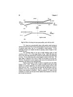
Fig
19.1 Desired loading pattern along contact line
for
maximum
strength.
Much
depends
on the
application since within
a
given gearbox (such
as the
previously mentioned
car
gearbox) there
may be
strength dominant
on
the two
lower
gears,
requiring bedding checks,
and
noise dominant
on the
three higher gears, requiring T.E. checks.
19.2 Design
for low
noise helicals
From
a
"philosophical" aspect
it is
relatively easy
to
design
for
maximum
strength.
If we
look
at a
helical gear
flank
as in
Fig.
19.1
we
need
to get the
maximum length
of
line
of
contact, compatible with reducing
the
load
to
zero
at the
ends
of a
line
of
contact. Within
the
line
of
contact,
the
objective
is to get the
loading
per
unit length constant over
the
length
of the
line.
This objective results ideally
in a
trapezoidal shape
to the
loading
distribution along
the
length
of the
line
of
contact. There
is
little choice
in the
resulting
"ideal"
design, apart
from how
fast
we
reduce
the
loading
at the
ends.
It
is
preferable
to use end
relief instead
of tip
relief
to
maximise
the
area
of
full
loading
or to use
"corner"
relief
if the
extra manufacturing cost
is
justified.
However,
to
achieve
a
good loading across
the
facewidth
the
helix alignments
must
be
extremely
good,
to
within, say,
20% of the
mean tooth deflection.
Strength versus Noise
283
effective
facewidth
Fig
19.2 Contact lines when
facewidth
is an
exact number
of
axial pitches.
In
designing
for low
noise there
are
more options available
and
much
depends
on
whether
or not
there
is a
good margin
of
strength
in the
design.
If we
could rely
on
perfect helix alignment,
life
would
be
fairly
simple
since,
apart
from tip
relief
and end
relief needed
to
prevent corner loading,
we
could
use
virtually
any
profile
at low
load.
At
high load,
if the
axial length
of the
gear
is an
exact number
of
axial
pitches then
the
contact lines
on the
pressure plane would always have
the
same total length. This
is
shown
in
Fig.
19.2
and
would give constant
mesh
stiffness,
hence constant elastic deflection
and a
smooth drive. Such
a
design
is, of
course, also
a
high strength design
if
there
is
negligible relief
at
the
tips
or
ends.
Unfortunately,
the
reality
is
that helix alignment
is
very rarely better
than
10
um
(0.4 mil)
and the
error
is
more likely
to be
much greater,
of the
same order
as the
theoretical elastic tooth deflection. This
end
loading
not
only puts
the
load concentration
factor
across
the
facewidth
(
C
m
or
K
ha
x
K},p)
up
above
2 or
even
3, but
prevents
the
helix
effects
from
averaging
out the
profile
effects.
We are
left
with
the
necessity
of
assuming that
the
helix
alignment will
be
poor
and
thus need
to
design accordingly.
284
Chapter
19
crowning
of
10
um
i
pinion
helix
shape
^**>
^
1
1
'
"^-^
\
nominal deflection
(20um)
\
X
deflected position with maximum
15^m
misalignment
^
.
^
facewidth
Fig
19.3 Helix matching
and
deflections
for a
compromise design.
One
approach
to the
problem, which
can be
used
if the
"design
condition" load
is
extremely low,
is to use
very heavy crowning
and a
perfect
involute
profile
with merely
a
chamfer
at the
tip.
A
smooth run-in
is
achieved thanks
to the
crowning,
and it is
permissible
to
dispense with conventional
tip
relief
if
loads
are low
since
the
teeth
are not
deflecting significantly. This type
of
design
is
quiet
at low
load
and
tolerates very high misalignments
but
cannot
be
loaded heavily
as the
lengths
of
contact
line
are so
short. Adding
tip
relief
to the
profile
allows
the
use of
moderate loads but,
as
with
a
spur
gear,
we
cannot
get low
T.E.
at
both
design
load (for which
we
need long relief)
and low
load (for which
we
need
short relief).
In
practice
we do not
normally have either perfect alignment
or
extremely
low
loads
to
allow
us to use the two
extreme designs
described
above,
so
compromises
are
necessary.
Fig. 19.3 shows
one
possible
compromise
pinion
helix shape where
we
have estimated
a
maximum
misalignment
of
±15
um
across
the
facewidth
and
expect
20 um
nominal tooth
deflection.
A
crowning
of 10 um
will
keep peak deflections
and
loadings
roughly
constant provided
the
helix mismatch stays within
15 um and at the
ends
a
further
end
relief
of 25 um
might
be
suitable.
The
wheel would then
not
be
helix relieved
at
all.
Profile
shape would
follow
normal
"spur
gear"
rules with
the
choice
between
"long"
and
"short"
relief
according
to
whether
best
performance
is
required
at
full
load
or low
load. Exact design
of the
relief
is
difficult
because
there
are
variations
in
deflections
of up to 10 um
across
the
facewidth
so
design
is
inevitably
a
compromise.
Strength versus Noise
285
The
previous comments were made
in
relation
to
standard proportion
20°
pressure angle gears. However,
as the
effect
of the
inevitable helix
mismatch
is to
move
the
characteristics more towards those
of
spur gears,
we
can
take this
to the
extreme
and
design
as if
they were spur gears.
The
ultimate
spur gear design,
as far as
noise
is
concerned,
is a low
pressure angle
tooth
with
an
effective
contact ratio
of 2
(requiring
a
higher nominal contact
ratio).
The
problem
is
slightly easier than
for an
actual spur gear
as tip
relief
is
not
needed, just
a
chamfer, because
a
smooth run-in
is
achieved
by the end
relief.
The
resulting gear should
be
quiet
at low and
high load whether aligned
well
or
not,
provided that
the
"spur"
profile
has the
correct long relief
and a
real contact ratio
of 2.
The
above comments apply
to
"rigid"
gear bodies without torsional
windup,
without radial wheel
rim
deflection
and
without bending
or
distortion
of
overhung
shafts.
If any
distortion
or
body deflection
effects
are
occurring
then
their
effects
have
to be
added into
the
estimates. This works backwards
by
assuming that
the
loading
is
even
across
the
facewidth, estimating
the
deflections
and
distortions
and
putting these into
the
calculations then
re-
estimating
the
loadings
if the
gear
is
corrected.
A
second iteration
may be
needed.
19.3 Design sensitivity
It
is
relatively easy, using
a
computer,
to
design
a
pair
of
gears which
will
be
perfectly quiet under
a
given
load.
All
that
is
then required
is to
make
them
accurately
and to
align
the
axes well
in the
gearbox,
and we
will then
have
a
perfectly inaudible
gearbox!!
If
only! Referring
to the
generation
of
T.E. illustrated
in
Fig. 19.4,
it is all too
clear that
a
dozen tolerances
of 2 um
(at
best)
are
going
to
have trouble
fitting
into
a
permissible
T.E.
of
perhaps
1
um.
The
reality
is
that
all the
factors
will
have errors, some relatively
small
at 2 um but
some large
at 5 to 10 um and
although elasticities will allow
some
averaging, there
are
likely
to be
relatively large variations.
The
difficulty,
and the
corresponding skill, lies
in
having
a
compromise design which
will
be
reasonably tolerant
of the
likely errors
in a
gear drive. Unlikely errors, such
as
having
a
profile
on one
tooth completely
different
from the
next tooth, should
not be
considered
but
reasonable errors
of
profile,
pitch
and
helix
matching should
be
allowed
for in the
design.
Realistically,
the
only
way to
assess
the
effects
is to
have
a
computer
model
such
as the one in
section
4.5 and to
vary
all the
tolerances
by
expected
manufacturing
errors
and
assess
the
effect
both
on
T.E.
(noise)
and on
peak
stress
loadings.
286
Chapter
19
Pinion
body
distortion
Thermal
distortions
Gearcase
deflection
Pinion
movement
Pinion
tooth
deflection
Pinion
profile
accuracy
Pinion
pitch
accuracy
Wheel body
distortion
STATIC
TRANSMISSION
ERROR
Gearcase
accuracy
Wheel
movement
Wheel
tooth
deflection
Wheel profile
accuracy
Wheel
pitch
accuracy
Pinion
helix
accuracy
Wheel
helix
accuracy
Fig
19.4 Contributors
to
mesh static T.E.
The
effort
involved
is
well worthwhile since
it is not
always obvious
what effects
the
changes
of
design
and
manufacturing variables will have
in
practice, either
on
strength
or
vibration.
The
danger with allowing
an
inexperienced designer
to use a
computer model
is
that they
will
take
the
simplistic view that whatever their
design,
if the
computer predicts that
the
T.E. will
be
zero,
then
the
design
is
"perfect."
This mindset then puts
all the
blame
for
trouble
on
"inadequate
production."
It is
important
to
educate
a
designer
that relatively large
(5
um,
0.2
mil) profile errors
and
larger helix
errors
are
inevitable
and
that their
design must
be
good enough
to
tolerate
errors,
from
both
aspects
of
stressing
and
noise.
19.4 Buying problems
When
buying-in
gears,
the
problems
fall
into
two
groups,
stress
and
noise, with
a
great
difference
between
the
degree
of
control
and
confidence
in
the
two
cases.
Strength
versus Noise
287
Currently
there
are few
problems associated with gear strength
and
durability.
Around
the
world,
a few
gear sets
fail
each year
but
failures
are
rare
and
invariably there have been silly mistakes made,
so
investigations
are
simple
and
straightforward
and
apportioning blame
is
relatively easy.
Often
the
problem
is due not to one
error
but to a
combination
of
errors.
As far as
the
buyer
is
concerned, specification
of the
drive that
it
should
be to
either
the
AGMA
or
ISO/DIN/BS
specification should produce
a
satisfactory result.
The
gear manufacturers dare
not
produce
an
inadequate strength drive (because
of
the
legal implications)
so
there
is
little
to
worry about.
A
glance
at the
computer printout
to
check that
a
sensible value
(>
1.5)
for
K
p
(the load
intensification
factor)
was
used
and
that
an
adequate
safety
factor
(2) was
present should
be
sufficient.
The
times this
may not be
adequate
are if a
ridiculously
low
diameter
to
length ratio
was
used
on the
pinion without helix
correction
or if
sharp corners were
left
to
give stress concentrations.
Noise
is
much more
difficult.
If
it is the
gearcase
itself which
is
going
to be the
noise emitter then,
as
with
a
hydraulic power pack,
specifying
the
total
sound power emitted
or
specifying, say,
77
dBA
at 1 m
distance
for a
machine tool,
or 60 dBA for an
office
device, will ensure
a
sufficiently
quiet
drive.
The
problem that arises
in
practice
is
that
it is
often
not the
gearbox
itself that emits
the
sound
but the
main structure,
as
discussed
in
section 10.2.
The
only worthwhile
tests
are
those
in
position
in the
unit
and it is
then
all too
easy
to
shuffle
blame between gearbox
and
installation.
A
knowledgeable customer
can
start
by
specifying
a
"reasonable"
T.E.
at
each mesh
in the
gearbox
but
this requires
a
sophisticated investigation
of
the
results obtained
in
situ with known levels
of
T.E.
in the
mesh. There
are
the
problems
of first
determining
a
tolerable level
and the
associated problem
that
often
neither
the
manufacturer
nor the
customer will
yet
have T.E.
measuring equipment
so
they cannot easily check, especially since
the
critical
value
is the
single
flank
error under load rather than under inspection
conditions. Attempting
to
specify
the
necessary quality
by
invoking
an
ISO
single
flank
quality level comes
to the
same thing
in
theory but, like
the
normal
quality checks, takes
no
notice
of
whether
it is
I/rev
or
1/tooth
that
is
important
or
whether both
are
within specification
but the
waveform
is
wrong
or
whether
odd
things happen under load
so a
specification
may be
wastefully
expensive.
Overall,
the
depressing
conclusion
is
that
the
buyer
is
rather
in the
dark
for a new
design
and has
little choice
but to put
their
faith
in a
manufacturer,
try the
result, then
if
trouble occurs, panic
and
measure T.E.
Dependent
on the
T.E.
level
the
buyer
can
then
try
another manufacturer,
attempt
to
reduce
T.E
levels
or
improve
the
tolerance
of the
installation, with
economics
in
control
as
usual.
288
Chapter
19
It
is
important, however, that initially
the
manufacturer
is
given
all
the
relevant information since this influences
the
design. Apart
from the
obvious information about
frequency of
overloads
or
whether
the
drive will
be
idling
most
of its
life,
it is
important that
the
designer knows what load levels
are
most critical
for
noise purposes
and
whether external loads
are
likely
to
distort
the
gearcase
and
affect
alignments.
Units
The
units used predominantly
in
this book
are the
official
SI
units
based
on
kilogrammes, metres
and
seconds.
A
force
of 1
Newton
is
defined
as
the
force
required
to
accelerate
1 kg at 1
m
s"
2
.
The
unit
of
work
is the
Joule
which
corresponds
to the
work when
1 N
pushes
a
distance
of 1 m.
This
is
also
the
basic unit
of all
electrical work
and all
heat.
1
Joule
per
second
is 1
Watt.
The
standard conversions
of the
base units are:
1
Ib
=
0.453592
kg
1
inch
=
25.40000
mm
From
these,
all the
others
are
derived,
and a
particularly
useful
one is
1
Ibfin'
2
=
6894.8
N
m'
2
so
that
the
Modulus
for
steel
(at 30 x
10
6
psi)
is 210 x
10
9
N
m'
2
.
The
corresponding density
is
7843
kg
m"
3
.
Stiffness
conversion
of 1
Ibffinch
is
175.13
N
m"
1
and so a
typical
good machine tool
stiffness
of one
million
IbFin
is
1.75
x
10
8
N
m"
1
The
unit
of
pressure
or
stress,
N
m"
2
is
called
the
Pascal, written
Pa,
but
it is
rather small
so a
useful
size
for
stresses
is
10
6
Pa or
MPa,
usually
written
by
structural engineers
as N
mm"
2
.
IMPa
(147 psi)
is
10
bar or 10
atmospheres.
For
steel
at 1
millistrain,
the
stress
is 210 MPa so
this
is a
typical
working
stress.
In
gears, working contact
stresses
range
up to
1500
MPa
(210,000
psi)
for the
contact
stresses
for a
case-hardened gear.
Stiffness
per
unit
facewidth
has the
same dimensions
as
stress
and so
the
same conversion
factor
of
roughly 7000 applies. This gives
the
"standard"
tooth
stiffiiess
of 2 x
10
6
IbFin/in
as 1.4 x
10
10
N
m'
1
m'
1
so
that
a
tooth
10
mm
wide
should have
a
stiffness
of 1.4 x
10
8
N
m"
1
.
As
far as
general measurements,
the
system insists that
all
sizes must
be
quoted
in
millimetres
on a
drawing
so a car may be
5683.375 long
and a
shim
may be
0.025. Centimetres, though
often
used
by
physicists
and in
Europe,
are
illegitimate.
Also
illegitimate,
though
not
uncommon,
is the
kilopond,
or the
weight
of a
kilogram
and
9.81
N. The
acceleration
due to
gravity
is
taken
as
289
290
Units
9.81
m
s"
2
,
though
in
practice
it
varies locally
so it is
often
not
possible
to use
dead
weights accurately
for
force because local gravity
is not
known with
sufficient
accuracy.
It
is
convenient that
the
metric Tonne
or
1000
kg has a
weight
of
roughly 10,000
N or 10 kN
which
is
almost exactly
the
same
as the
imperial
Ton of
2240
Ib.
Manufacturing
accuracies
are in
microns
(uin),
roughly
0.4
tenths
of a
mil
(thou) since 25.4 microns
are 1
mil. This size
of
unit
is
ideal
and is far
better
for
quoting than
"halves
of
tenths
of a
thou"
for
present
day
accuracies.
Oil
viscosities start
to get
complicated especially
as
initial conversions
from
units
such
as
Redwood
sees
are
required.
1
Poise
is
0.1
N s
m"
2
and 1
Stoke
is
lO^mV.
One
great advantage
is
that
the
units
of
work
are
common
to all
branches
of
engineering
so
that
1 N at 1 m
s"
1
is
doing
1
Watt
of
work
and
mechanical
to
electrical conversions
are
much simplified
so it is
easy
to
compare, say, energy storage
in a flywheel and a
capacitor.
Index
Absorber
tuned,
179
untuned,
181
Accelerometer
amplifier,
79
output,
80
Accuracy
damping,
74
encoders,
110
of
T.E. estimates,
53
profile
measurement,
38
Adjacent
pitch errors,
43
Aliasing,
127
Amplifier,
charge,
79
Anti-noise,
2
Antiresonance,
248
Archiving,
136
Asperity shocks,
240
Averaging
description,
152
effects,
154
for
compression,
132
for
1/tooth,
155
for
scuffing,
233
subtraction,
157
for
wear,
233
Axial
vibration
transmission,
7, 263
Axial
effects
on
alignments,
55
forces,
31
Axle
temperature,
113
Backlash
measurement,
113
elimination,
193
Bandwidth
broadening,
148
frequency,
147
Base circle
radius,
3,
4
Base pitch
definition,5
equality,
5, 13
on
Harris map,
21
Bearings
cooling,
204
limitations,
203
monitoring,
241
scaling,
273
Bedding check,
281
Bending
pinion,
57
shaft,
57
Borderline power,
152
Bouncing,
191
Buttressing,
39
Calibration
accelerometer,
85
back
to
back,
110
charge
amplifier,
84
hammer,
253
Cambridge
univ,
10
CD
writer,
136
Centre
distance
limit,
109
Cepstrum,
163
291
292
Index
Charge amplifier,
79
Chirp,
255
Churning, oil,
279
Circ-arc,
2
Coherence,
260
Combining
responses,
257
Compression
of
information
averaging,
132
enveloping,
133
line
amalgamation,
135
Computer
limits,
123
Contact
deflections
53
ratio, definition,
4
resonance,
82
shock,
33
stiffness,
54
Convection cooling,
279
Conversion, line
to
PSD,
147
Corner loading
oil
film, 30, 40
stresses,
30
Corner
relief,
30
Corrections
crowning,
44
helix,
44
Coupling
gear
tooth,
268
testing,
265
vibration,
266
Cracking
vibrations,
235
Crest factor,
238
Crowning,
44
Current-voltage conversion,
83
Cycloidal,
3
Damper
tuned,
179
untuned,
181
Damping
assumptions,
75
increasing,
179
levels,
72
too
high,
72
tooth,
74
Debris
detection,
241,274
groups,
275
scratching,
276
Decoupling inertia,
192
Dipole,
170
Dirac impulse,
250
Distortions, gears,
56
Dither,
153
Double
flank
checking,
10
Dropped tooth model,
140
Dynamic
program,
66
Dynamics
internal,
105
Eccentricity
effect,
41
modelling,
141
Effective
mass,
247
Elimination
of
lines,
158
Encoders
accuracy,
110
choice,
106
dynamics,
101
mounting,
108
original,
93
parameters,
107
End
relief,
29
Enveloping,
133
Epicyclic
definition,
203
Equipment
hire,
10,
11
Equivalent
stiffness,
67
inertia,
67
Errors
encoders,
110
generation,
140
Excitation
choices,
245
Index
293
Filter
chips,
130
cost reduction,
129
line removal,
158
number
of
poles,
130
oil
specification,
275
requirements,
128
ringing,
129
Fluid couplings,
242
Force
impact,
252
position variation,
32
radial
bearing,
32
Fourier
ideas,
142
fast,
143
Frequency
analysis,
142
changing,
178
folding,
128
integration limits,
125
Nyquist,
128
pitch
errors,
163,
164
ranges,
127
sampling,
127
scaling,
171
Friction
effects,
2
reversal,
33
Gear tooth coupling
bending
effects,
277
lockup,
278
vibration,
268
Ghost notes
cause,
165
false,
165
Goulder
tester,
94
Gray staining,
270
Gregory, Harris,
Munro,
5
Grumbling,
139
Hall
probe,
90
Hammer
calibration,
253
force
measurement,
252
frequencies, 251
testing, 250,
255
Hanning
window,
148
Harris
maps,
13,
22
Heidehain Ltd.
encoders,
95,
107
Helical
effects
alignments,
55
axial forces,
31
elasticity,
27
no
load,
35
Helix
corrections,
44
crowning,
44
end
relief,
44
match,
46
twisting,
56
High contact ratio gears
design,
216
penalties,
219
reasons,
215
stifmess,
219
T.E. measurement,
219
two-stage
relief,
217
Huddersfield,
University,
10
Hypocycloidal,
3
Impedances,
83
Impulse
Dirac,
250
power,
256
testing,
255
Inertia decoupling,
192
Integration
digital,
125
double,
104
frequency
range,
125
294
Index
to
velocity,
81,124
Interpolation,
95
Involute
properties,
3
shape,
3
Integration circuit,
81
Irritation
types,
139
Isolator
attenuation,
89
improvement,
171
non-linear,
90,
173
response,
172
Jerk definition,
126
Jitter
cause,
155
effect,
156
reduction,
157
Jumps,
non
linear,
190
Kennedy
and
Pancu.
87
Klingelnberg,
119
Kurtosis,
231
Laser
vibrometer,
82
Lanchester
dampers,
181
Line
removal
effect,
159,238
reason,
158
routine,
160
Line
of
action
definition,
3
Load sharing
need,
201
unbalance,
278
Low
contact ratio
gears
curvature,
227
frequencies, 229
reasons,
223
shapes,
224
tip
relief,
226
tip
stresses,
227
Marker
magnetic,
90
once
per
rev,
90
Matlab,
59
Mesh
cycle,
132
stiffness,
14
Microphone,
77
Micropitting
cause,
270
frequencies, 271
Microslip
cause,
116
prevention,
117
Misalignment
checking,
114
Mode shapes
rib
effect
170
typical,
168
Model
dynamic,
61
2D,
61
2
stage,
63
Modulation
amplitude,
162
causes,
161
frequency, 159
tone,
139
synthesis,
141
Newcastle
Design
Unit.,
10
Noise
character,
140
electrical,
1
generation,
1
meter,
79
types,
139
variations,
182
white,
142
Non
dimensional factor,
171
Non
linear vibrations
Index
295
causes,
185
effects,
185
simple
predictions,
189
Notch
filter, 158
Nyquist
frequency, 128
Ohio State University,
11
Oil
trapping,
2
Opto
switch,
90
Panel
improvement,
168
Particle counts,
274
Peak impact force,
191
Phantom
cause,
165
false,
165
Phase
locked loop,
102
Phasing
harmonics,
250
planets,
205
Pinion bending,
57
Pitch
errors
adjacent,
43
apparent,
41
frequencies, 163
generation,
140
modulation,
140
random,
42
small,
41
use of, 140
Welbourn,
42
Pitting
cause,
269
vibrations,
234
Planetary
gears
definitions,
203
excitation phasing,
205
frequencies, 208
load
sharing,
203
speed
ratio,
209
I.E.
testing,
209
unexpected
frequencies,
211
Plastic deformations,
229
Power
splitting,
201
Pressure angle
property,
4
Pressure line
definition
3, 13
Pressure plane,
28
lines,
32
view,
45
Profile
consistency,
41
measurement accuracy,
38
Program
Matlab,
48
I.E.
estimation,
48
dynamic,
66
Propeller
vibration,
7
PSD
conversion,
147
definition,
146
Pulses
buildup,
143,250
frequencies, 251
half
sine,
251
injection
interpolation,
95
measurement,
252
slowing down,
90
Ratio
approximate,
115
routine,
115
Rattle
modelling,
194
program,
197
system,
195
Receptances,
257
Reciprocal theorem,
254
Rectification
by
capacitor,
133
circuit,
135
linear,
134
296
Index
Relief
crowning,
44
end,
29
intermediate,
23
helix,
44
load
pattern,
30
long,
23
near
crossover,
24
short,
23
tip
model,
47
Remond,
97
Resonance
contact,
82
external,
87
internal,
85
Responses
combining,
257
external,
8
internal,
6
Restitution coefficient,
74
Revolution marker,
90
Rigidity, plate,
170
Roll
angle,
17,
19
Roll checking,
10
Root relief,
19
Rouverol,
33
Rubber choice,
179
Running
in, 240
Scaling
frequencies,
178
Scrap
rates
reduction,
181
pairing
effects,
182
Scratching,
flank,
276
Scuffing
vibrations,
236
detection,
238
Servo valves,
249
Shaft
bending,
57
Signal
to
noise
ratio,
1
recording,
122
Silhouetting,
33
Single
flank
checking,
10, 93
Slice interferences,
28
Slip
speeds,
242
Smearing
cause,
155
effect,
156
reduction,
157
Smith
shocks
debris detection,
241
running
in, 240
scuffing,
238
Sound
intensity,
78
measurement,
79
reflection,
77
speed,
77
Spalling,
270
Spectrum
continuous,
145
conversion,
147
line,
146
Speed
of
sound,
77
Stability
of
program,
71
Statistical energy,
8
Step length
Stepper motor
errors,
166
Stiffness
isolator,
171
mesh,
13, 14
Stress wave intensity,
34
Surface
healing,
273
Swash, modulation,
161
Sweeney
and
Randall,
97
Sweep testing,
255
Tangential
accelerometers,
103
Thermal growth,
263
Thin slice
assumptions,
38
load
variations,
39
Thrust cones,
31
Index
297
Time
averaging, 132,
152
marching,
64
step,
71
Tip
relief
amount,
16
linear,
17
load
pattern,
30
long,
23
model,
47
reasons,
15
short,
23
wear corrected,
19
Tolerance combinations,
182
Tooth
deflection,
13
stiffness,
14
damping,
74
Torsional
acceleration,
103
vibration,
97
Transient, starting,
69
Transmission error
basic idea,
3
conversion,
5
definition,
5
drift,
117
effect
of
size,
6
estimation,
48
high
speed,
100
load
effects,
22
measurement,
93
misaligned,
114
noise crosscheck,
10
noise relationship,
9
noise
synthesising,
140
predictions,
49
program,
48
reduction,
174
permissible,
176
shape,
177
storage,
124
testing planetary,
209
unloaded,
19
variability,
183
zeroing,
115
Transmission path,
9
Tuma,
97
Tuned
absorber,
179
Velocity
integrated
accel.
81
laser measurement,
82
permitted level,
126
Vibration
excitation
path,
9
types,
2
Vibrator
electromagnetic,
245
hydraulic,
249
Wavelets, use,
160
Welbourn
pitch errors,
42
White
noise
adding,
142
components,
143
testing,
255
Wildhaber-Novikov,
2
Windows
reasons
for, 148
rectangular,
150
Wind
turbine,
7, 263
Windup
corrections,
56
Worm
axis adjustment,
112
колхоз
1/10/07