Handbook of Lubrication Episode 1 Part 13 docx
Bạn đang xem bản rút gọn của tài liệu. Xem và tải ngay bản đầy đủ của tài liệu tại đây (673.77 KB, 21 trang )
If no viscosities are known, the critical viscosity may be estimated from the values of P
cr
,
T
cr
, and molecular weight M, as follows:
(6)
Table 4 illustrates the application of the two methods to the calculation of the viscosity
of nitrogen. For each temperature, T
r
is calculated from T
cr
= 126.3 K. Next are listed the
Volume II 297
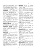
FIGURE 4. Generalized reduced viscosity of gases. (From Hougen, O. A., Watson, K. M., and
Ragatz, R. A., C.P.P. Charts, 2nd ed., John Wiley & Sons, New York, 1960. With permission.)
Table 4
COMPARISON OF ESTIMATED NITROGEN VISCOSITIES AT 1 BAR
291-300 4/10/06 12:48 PM Page 297
Copyright © 1983 CRC Press LLC
values of μ
r
estimated from Figure 4 from the low density limit curve. Assuming we know
the viscosity is 17.9 ×10
–6
Pa·sec at 300 K where μ
r
is estimated to be 1.00, the value of
μ
cr
is the same and the viscosities at the other temperatures are directly calculated as shown.
If no viscosities are known, Equation 6 is used:
μ
cr
= 7.70 ×10
–7
(28.02)
0.5
(34.0)
0.667
(126.3)
–0.167
= 19.1 ×10
–6
Values for the other temperatures are calculated directly from the estimated values of μ
r
.
The final column shows the actual viscosities, indicating a reasonable check.
For convenience, the following are conversions to the SI system: 1 reyn =1.45 ×10
–10
Pa·sec and 1 P=0.1 Pa·sec.
Specific Volume
The specific volumes listed in Table 1 indicate the degree of “perfection” of a gas. At
273.1 K and I bar pressure, 1 g-mol of a perfect gas occupies a volume of 22.4 ᐉ. Adjusting
this to 300 K gives 24.6 ᐉ. If the specific volumes in Table 1 are multiplied by the molecular
weight for each gas, the result is liters per gram mole (ᐉ/g-mol) and also cubic meters per
kilogram-mole (m
3
/kg-mol). Values for air, nitrogen, and oxygen are 24.9. Freon 21, Freon
11, and sulfur dioxide are below the perfect gas figure, indicating some degree of association
between molecules.
Pressure is given here in bars or atmospheres. For use in the SI system, 1 bar is equivalent
to 101,300 Pa.
APPLICATION OF DATA
Hydrodynamic bearings principally require knowledge of the viscosity of the gas at the
temperature and pressure involved. When the pressures are very low or the spacing between
surfaces is very small, consideration must be given to the mean free path. Hydrostatic
bearings involve feeding of gas at an elevated pressure into the bearing film area. Viscosity
is required in calculating the flow through the film; thermal properties are required in
calculating flow through feed orifices or ports. Sonic velocity sets a limit on flow rate in
these situations.
Hydrodynamic and Hydrostatic Designs
The viscosity enters directly in hydrodynamic calculations through the principal terms in
Reynolds equation which are of the form:
Because of the usually good heat transfer to the surfaces, hydrodynamic films are treated
as isothermal and at the bearing surface temperature. Ambient temperature and pressure
conditions are adequate for the determination of operating viscosity from the data in the
previous section.
In hydrostatic design computations, one is concerned with mass flow through thin slots
obeying the equation:
(7)
where the kinematic viscosity ν=μ/ρ enters. Here h is the slot thickness, ρ is the mass
density, and w is the slot width. Where turbulence may be involved, the kinematic viscosity
298 CRC Handbook of Lubrication
291-300 4/10/06 12:48 PM Page 298
Copyright © 1983 CRC Press LLC
enters in the Reynolds number:
\
(8)
where U is the velocity of one surface relative to another a distance h away.
Feed restrictors to a hydrostatic gas bearing are more commonly of the orifice type rather
than of the laminar flow type. For discharge of a perfect gas through an orifice,
(P
1
/P
2
)
α
= T
1
/T
2
(9)
where T is the absolute temperature. The exponent a is usually expressed in terms of the
ratio of specific heats, k = C
p
/C
v
, but can also be expressed in terms of the gas constant
R, C
p
, and the molecular weight M:
α=(k – 1) /k = R/C
p
M (10)
The limiting pressure ratio at which the throat velocity equals the speed of sound is given
by:
(11)
The key constant α can be calculated directly from Equation 10.
As an example, consider the monomolecular gas argon with a molecular weight of 39.94
and a heat capacity at 300 K of C
p
= 0.522 kJ/kg·deg. For argon at 300 K, α=8.314/
(0.522 × 39.94) = 0.399, and r
c
= (0.601/0.8005)
1/0.399
= 0.488. This is equal to the
theoretical value for a perfect gas of 0.49.
Mean Free Path
The mean free path is a measure of the average distance between collisions of the gas
molecules. It is a function of the volume density of the gas and is given by:
λ=1/(1.414μσ
2
n) (12)
where σ is the molecular diameter and n is the molecular density in molecules per cubic
centimeter. The number of molecules per gram-mole is Avogadro’s Number, 6.02 × 10
23
.
As an example, the molecular density of argon at 273 K is
n = 6.02 × 10
23
/22,440 = 2.69 × 10
19
The molecular diameter is approximately 2.9 × 10
–8
cm. Applying Equation 12:
λ=1/ [1.414π (2.9 × 10
–8
)
2
× 2.69 × 10
19
] = 9.9 × 10
–6
cm
The value estimated in the Handbook of Chemistry and Physics is 9.0. This accuracy is
quite sufficient for low pressure or very thin film bearing design.
Speed of Sound
Speed of sound in a gas is a function of temperature, molecular weight, heat capacity at
constant pressure, and the gas constant:
Volume II 299
291-300 4/10/06 12:48 PM Page 299
Copyright © 1983 CRC Press LLC
(13)
Applying this data to oxygen, Table 1 lists M =32.00, and C
p
= 0.920 kJ/kg·K. Using
this data in Equation 13 yield 329 m/sec, as compared with the value of 353 m/sec listed
in Table 1.
NOMENCLATURE
C = Temperature, C
C
p
= Specific heat at constant pressure, kJ/kg·K
C
v
= Specific heat at constant volume, kJ/kg·K
P = Pressure, N·m
–2
T = Absolute temperature, K
T
B
= Boiling point, K
U = Surface velocity, m/sec
h = Film thickness, m
M = Molecular weight
w = Width of leakage path, m
ν=Kinematic viscosity, m
2
/sec
λ=Mean free path, m
μ=Absolute viscosity, Pa·sec
ρ=Mass density, kg/m
3
Φ=Sonic velocity, m/sec
REFERENCES
1. Vargaftile, N. B., Tables on the Thermophysical Properties of Liquids and Gases, 2nd ed., John Wiley &
Sons, New York, 1975.
2. Bird, R. B., Steward, W. E., and Lightfoot, E. N., Transport Phenomena,, John Wiley & Sons, New
York, 1960.
3. Uyehara, O. A. and Watson, K. M., Natl. Pel. News, 36, 764, 1944.
4. Hougen, O. A., Watson, K. M., and Ragatz, R. A., C.P.P. Charts, 2nd ed., John Wiley & Sons, New
York, 1960.
300 CRC Handbook of Lubrication
291-300 4/10/06 12:48 PM Page 300
Copyright © 1983 CRC Press LLC
LUBRICATING OILADDITIVES
J. A. O’Brien
INTRODUCTION
The modern history of lubricant additives began in the early 20th century with the use of
fatty oils and sulfur in mineral oils to improve lubrication under high loads. World War II
provided a major impetus to the development of lubricant additives as the military, engine
builders, and machine manufacturers demanded more performance from their equipment.
Consumption of lubricant additives in the U.S. increased from 127 thousand metric tons
in 1950 to 710 thousand metric tons in 1978.
1
Lubricants for internal combustion (IC)
engines account for 72% of the market. Total free-world consumption of lubricant additives
is estimated to be about three times that of the U.S.
The unique feature of IC engine lubricants is their exposure to combustion products from
blow-by, fuel combustion products which leak past piston rings and contact the lubricant.
Blow-by contains unburned fuel, reactive intermediates of fuel oxidation, fixed nitrogen in
the forms of nitrogen oxides, and their fuel reaction products, soot, products of fuel additives,
sulfur oxides, carbon monoxide, carbon dioxide, and water. IC engine lubricants require
extensive additive treatment to counteract the effects of blow-by, such as internal engine
rust, bearing corrosion, surface deposits which interfere with engine clearances, sludge
formation which blocks lubricant passages, and lubricant decomposition.
Some industrial lubricants, such as those used in a steel or paper mill, also encounter
severe environments and contamination. External and internal environments may subject
lubricants to severe oxidizing conditions, extreme pressures and temperatures, water, dust,
metal catalysts, and active chemicals.
ADDITIVE FUNCTIONS
Many minerals are used as lubricant additives, far too many to list in detail. Ramney
published three texts
2,3,4
listing recent additive patents. This chapter discusses some of the
more widely used additives, emphasizing their primary performance characteristics. Chem-
ical structure and manufacture of some major lubricant additives are included in the Appendix.
Boundary Lubrication Additives
In boundary lubrication, surface asperities contact each other even though the lubricant
supports much of the load. Friction depends mainly on the shearing forces necessary to
cleave these adhering asperities and wear and friction can be reduced by certain additives.
Table 1 lists common boundary lubrication additives.
Wear inhibitors and lubricity agents are polar materials that adsorb on a metal and provide
a film that reduces metal-to-metal contact. Extreme pressure (EP) additives are a special
class of boundary lubrication additive which react with the metal surface to form compounds
with lower shear strength than the metal. This low-shear compound provides the lubrication.
Friction modifiers can either adsorb or react with the surface to reduce friction by forming
a very low shear-strength film. For example, Figure 1 demonstrates the effect of a friction
modifier in an automatic transmission fluid. Without a friction modifier, the friction coef-
ficient in the transmission would increase at low-sliding velocity where surface asperities
make contact. This would result in rough shifting and lead to high-transmission loading and
driver discomfort in vehicles. The friction modified fluid now in common use permits smooth
shifting at low speeds while it maintains adequate friction under normal driving to prevent
Volume II 301
301-315 4/10/06 12:51 PM Page 301
Copyright © 1983 CRC Press LLC
or (2) deactivate corrosive contaminants in the lubricant. Certain additives that inhibit cor-
rosion in some environments can actually cause corrosion in others. For example, zinc
dithiophosphates inhibit copper-lead bearing corrosion in an oxidative environment, yet cause
silver bearing distress from sulfidation. When used in high concentrations, zinc dialkyldi-
thiophosphates can also pit some ferrous metals.
Oxidation Inhibitors
Oxidation, the most common form of lubricant deterioration, proceeds through free-radical
reactions which are accelerated by heat and catalyzed by metals. In hydrocarbon lubricants,
free-radicals react with oxygen to form peroxy free-radicals which attack hydrocarbons to
form new free-radicals and hydroperoxides. Free-radicals are formed faster than they are
used and the rate of oxidation increases.
Some hydroperoxides decompose into aldehydes, ketones, carboxylic acids, and other
oxygen-containing hydrocarbons. The oxygen compounds polymerize to form viscous soluble
materials (lubricant thickening) and insoluble materials (sludge and deposits.) Some of the
oxygen compounds are active, polar materials that accelerate rust and corrosion.
Volume II 303
FIGURE 2. Effect of friction modifier in engine crankcase lubricant.
Table 2
CORROSION INHIBITORS
301-315 4/10/06 12:51 PM Page 303
Copyright © 1983 CRC Press LLC
Oxidation inhibitors (Table 3) generally function by one or more of three mechanisms:
free radical inhibition, peroxide decomposition, or metal deactivation. Each mechanism
inhibits oxidation at a different link in the chain reaction. Hindered phenols, such as 2,6-
di-t-butyl-para-cresol (DBPC), are effective free-radical oxidation inhibitors because they
react with free-radicals to form nonfree-radical compounds. Some sulfur compounds de-
compose peroxides into stable compounds. Some selective polar additives react with metal
ions and surfaces to inhibit their catalytic activity and are known as metal deactivators.
Detergents and Dispersants
Both detergent and dispersant additives (Table 4) are polar materials which provide a
cleaning function. Detergency is a surface phenomenon of cleaning surface deposits. Dis-
persancy is a bulk lubricant phenomenon of keeping contaminants suspended in the lubricant.
Detergent and dispersant additives each perform both of the above functions and differ in
their relative ability to function at the machine surface or in the bulk of the lubricant.
Viscosity Modifiers
Viscosity index (VI) improvers (Table 5) are polymers that cause minimal increase in
304 CRC Handbook of Lubrication
Table 3
OXIDATION INHIBITORS
Table 4
DETERGENTS AND DISPERSANTS
Table 5
VI IMPROVERS
301-315 4/10/06 12:51 PM Page 304
Copyright © 1983 CRC Press LLC
lubricant viscosity at low temperature, but considerable increase at high temperature. Table
6 demonstrates the effects of a VI improver. Atypical 100 VI SAE 40 viscosity grade oil
has proper viscosity (14 cSt) for engine lubrication at 100°C, but is too viscous (15000 cP)
to permit engine starting at –18°C. Atypical 100 VI SAE 10Woil would permit engine
starting at – 19°C, but is not viscous enough to protect the engine from wear at 100°C. By
adding a VI improver to the SAE 10Woil, the product can permit engine starting at –18°C
and still protect the engine from wear at 100°C.
Many of the same chemicals are also used as thickeners to increase the viscosity of
products for special applications such as gear oils. Molecular weight may be varied to
optimize specific performance characteristics. Viscous petroleum fractions, such as bright
stocks, are also used as thickeners but are not considered additives.
PourPoint Depressants
Petroleum oils contain paraffinic wax which crystallizes in a lattice-like structure as the
lubricant cools and prevents the lubricant from flowing. The lowest temperature at which
the lubricant flows is called the pour point. Pour point depressants co-crystallize with the
paraffinic wax, modify growth of the lattice-like structure, and permit flow at temperatures
below the pour point of the unmodified lubricant. Common pour point depressants include:
polymethacrylates, wax alkylated naphthalene polymers, wax alkylated phenol polymers,
and chlorinated polymers.
Emulsion Modifiers
Emulsifiers give stable emulsions of water-in-oil or oil-in-water. They are used where
high amounts of water improve cooling due to the high specific heat and thermal conductivity
of water. Lubricants which contain water are increasingly being used to conserve petroleum
base stocks.
Demulsifiers make emulsions unstable, which permits separation of water and lubricant.
They are particularly important where water contamination can damage the lubricant in
marine or industrial applications. Emulsion modifiers change the interfacial tension of oil
and water. Low-interfacial tension permits stable emulsions. Table 7 lists emulsion modifiers.
Foam Decomposers
Excessive lubricant foaming can cause an overflow of the lubricating system, displace
lubricant in pumps, increase response time of hydraulic systems, and disrupt the lubricant
supply. Two theories predominate on the function of foam decomposers. The first is that
they increase gas-lubricant interfacial tension to the point where the bubbles collapse. The
second is that these partially soluble compounds with low-surface tension cause openings
in the bubbles which allow the gas to escape.
Foam decomposers function at concentrations from 1 to 50 ppm. High concentrations can
lead to excessive foaming, more than the original lubricant, and increased air entrainment.
Common foam decomposers include: polysiloxanes (silicones), polyacrylates, organic co-
polymers, and candellilla wax.
Volume II305
Table 6
EFFECT OF VI IMPROVER
301-315 4/10/06 12:51 PM Page 305
Copyright © 1983 CRC Press LLC
rust inhibitors function by adsorbing on metal surfaces and they compete for the same surface.
The wear inhibitor can displace the rust inhibitor on the surface and be detrimental to rust
inhibition. Likewise, the rust inhibitor can displace the wear inhibitor.
Meeting Performance Requirements
Universal engine lubricants meet the performance requirements of passenger car gasoline
engines, as well as turbocharged two-stroke cycle and four-stroke cycle truck diesel engines.
The additive package requires a very careful balance because it deals with diverse, complex
quality requirements. Passenger car engine lubricant requirements in the U.S. are defined
by a series of laboratory engine tests designated SF
8
by the American Petroleum Institute
(API). The SF designation signifies that the lubricant passed the tests shown in Table 8.
Truck diesel engine lubricant requirements in the U.S. are designated CD.
9
To obtain the
CD designation, the lubricant must pass the tests shown in Table 9. Most engine lubricant
requirements outside the U.S. also require SF or CD performance plus additional local
performance requirements.
Each SF and CD test stresses certain performance aspects of the lubricant and has been
correlated with field experience. The IID test simulates short-trip winter driving, which is
the most severe rust-forming condition. The IIID test simulates high-speed, high-load, and
high-temperature driving conditions, such as towing a camper-trailer across the desert in the
summer at high speed, which are severe for oxidative thickening and wear. The VD test
simulates continuous stop-and-go city driving with an overhead cam engine — a severe
condition for sludge and varnish formation and cam wear. The 1-G2 test simulates a heavily
loaded, turbocharged, four-stroke diesel using high-sulfur fuel. The L-38 test stresses pro-
tection of copper-lead bearings from corrosion. In addition to passing all SF and CD tests,
a universal engine oil must also have less than 1% sulfated ash to be compatible with two-
stroke cycle diesel engine performance. Lubricant formulation involves handling all of these
conditions with the same lubricant.
Volume II 307
Table 8
SF ENGINE LUBRICANT TESTS
8
Table 9
CD ENGINE LUBRICANT TESTS
9
301-315 4/10/06 12:51 PM Page 307
Copyright © 1983 CRC Press LLC
Table 10 shows how the additives commonly used in universal engine oils perform in the
major aspects of the SF and CD sequence tests. Additive formulation for most lubricants
involves similar consideration of beneficial and detrimental additive effects.
Relationship of Additives and Base Stocks
Lubricant base stocks influence additive performance through two main functions; solu-
bility and response. For example, performance of surface active additives depends largely
on their ability to adsorb on the machine surface at the proper time and place. Base stocks
with poor solubility characteristics may allow these additives to separate before they can
fulfill their intended functions. Conversely, base stocks with very high-solubility charac-
teristics may keep the additives in solution, not allowing them to adsorb.
Additive response depends on base stock composition. Natural sulfur, nitrogen, and
phenolic inhibitors are removed along with undesirable materials during base stock refining.
Removal of these natural inhibitors often results in reduced oxidation inhibition relative to
unrefined stocks. However, the natural inhibitors, as well as the undesirable materials
removed during base stock refining, often interfere with additive performance.
Synthetic base oils, depending on their chemical structure, exhibit very specific solubility
characteristics, additive response, and additive compatibility that are sometimes different
from mineral oils. The most common synthetic base oils are synthetic hydrocarbons, such
as polyalpha olefins, and esters, such as adipate, azelate and pentaerythritol esters.
Synthetic hydrocarbons exhibit excellent additive response but are poor additive solvents.
Esters vary in additive response and are excellent solvents except for additives with which
they react to form precipitates. Synthetic oils can be blended with each other or with mineral
oil to provide the optimum balance of solubility and additive response.
Formulation
Additive formulation requires consideration of interaction and competition among additives
as well as individual additive performance and solubility. Undesirable additive side-effects
must be overcome and the total additive formulation balanced to achieve optimum perform-
ance in the finished lubricant.
Often the solution to a lubricant formulation problem lies not in changing the relative
308 CRC Handbook of Lubrication
Table 10
EXAMPLE OF ADDITIVE EFFECTS IN UNIVERSAL ENGINE
LUBRICANT
Note: Key: +++, very beneficial; ++, beneficial; + , slightly beneficial; = , no effect; – ,
detrimental; and – – , very detrimental.
301-315 4/10/06 12:51 PM Page 308
Copyright © 1983 CRC Press LLC
concentration of an additive, but in changing the additives themselves. Molecular weight,
molecular weight distribution, reaction conditions, purity, and many other variables influence
these parameters. Small amounts of chemicals added during additive manufacture often
induce large changes in additive interaction performance. These “additive additives” are
considered highly proprietary by additive manufacturers.
ACKNOWLEDGMENT
The author expresses sincere appreciation to Roger Watson of Batavia, Illinois, who
consulted on chemical accuracy, authored the appendix, and provided constructive sugges-
tions for the other aspects of the chapter. Assistance received from many members of the
Amoco Research Center, Naperville, Illinois, is also gratefully acknowledged.
APPENDIX: EXAMPLES OF LUBRICANT ADDITIVES
A description of representative additives follows. Some additives are relatively pure
chemicals, for example, the zinc dithiophosphates. Many additives, however, are reaction
products of industrial grade chemicals using reaction conditions to control the product quality
and performance. In these cases, the complex mixture is not extensively separated and the
structures shown represent the major component of a generic group. A vast literature describes
additive properties and preparation in more details.
2,3,4,13,14
1. Metal Dialkyldithiophosphates (Metal Dialkyl Phosphorodithioates)
Variations — M is usually zinc but may also be molybdenum, tungsten, or other metals.
The R–O– groups are derived from primary and secondary alcohols and alkyl phenols and
may be single or mixed.
Manufacture — Alcohols or alkyl phenols are reacted with P
4
S
10
to form the dialkyl-
dithiophosphoric acids. The zinc salts are made by reacting the acids with zinc oxide.
Application — Antiwear, anticorrosion, and antioxidant used almost universally in
lubricants.
2. Tricresyl Phosphate
Manufacture — Mixed cresols (except ortho) reacted with phosphorous oxychloride.
Application — Wear inhibitor for synthetic oils and greases.
Volume II 309
301-315 4/10/06 12:51 PM Page 309
Copyright © 1983 CRC Press LLC
3. Sulfurized Fats, Olefins, Hydrocarbons
Variations — The R groups are residues from olefin polymers, petroleum stocks, un-
saturated fats, terminal olefins, and terpenes.
Manufacture — Selected fats and hydrocarbons are heated with sulfur, sometimes in the
presence of an alkaline catalyst.
Application — Antioxidants, antiwear, and antifriction are widely used in industrial
lubricants including cutting oils and gear oils.
4. Benzotriazole
Manufacture — Nitrous acid on o-phenylene diamine.
Application — Inhibitor for sulfur corrosion of silver and copper in industrial lubricants.
5. 2-Alkyl-4-Mercapto-1,3,4-Thiadiazole
Variations — 2,4-bis (alkyldithio)-1,3,4-thiadiazoles. R is -octyl or -dodecyl.
Manufacture — Hydrazine and carbon disulfide are condensed to form the dimercapto
thiadiazole, which is then coupled with tertiary mercaptan using hydrogen peroxide.
Application — Inhibitors for sulfur corrosion of silver and copper; wear and oxidation
inhibitors in industrial lubricants.
6. Metal Dialkyldithiocarbamates
Variations — M may be any of a variety of metals, including zinc and molybdenum. R
is C
4
to C
10
. x is a function of the metal valence.
Manufacture — Secondary amines are reacted with carbon disulfide and caustic solution.
The sodium dithiocarbamate is then reacted with the metal chloride.
Application — Antioxidants and antifriction additives.
310 CRC Handbook of Lubrication
301-315 4/10/06 12:51 PM Page 310
Copyright © 1983 CRC Press LLC
7. 2,4-Ditertiarybutyl-p-Cresol (DBPC)
Variations — This is the most important member of a class called hindered phenols.
Several variations are formed by coupling two phenolic groups through the ortho or para
positions by methylcne groups, sulfur, or nitrogen.
Manufacture —p-Cresol is ortho alkylated using aluminum alkyl catalyst.
Application — Antioxidants widely used in many kinds of lubricants.
8. Phenothiazine
Variations — Ring alkyl groups.
Manufacture — Reaction of diphenylamine with sulfur.
Application — Antioxidant in synthetic oils for jet engines and in greases.
9. Phenyl Alpha Naphthylamine (PAN)
Variations — Ring substitutions.
Manufacture — 1-Napthyl amine heated with phenol.
Applications — Antioxidants for greases and synthetic oils.
10. Dialkyldiphenylamine
Variations — R may be phenyl or alkyl derived from olefins.
Manufacture — Aniline is heated with strong acid to yield diphenylamine which is then
alkylated with chlorobenzene or olefin polymers.
Applications — Antioxidants for greases, mineral oils, and synthetic oils.
Volume II 311
301-315 4/10/06 12:51 PM Page 311
Copyright © 1983 CRC Press LLC
11. Phosphosulfurized Pinene
Variations — R is derived from either alpha or beta pinene or a turpentine mixture.
Manufacture — Pinene is reacted with P
4
S
10
.
Application — Antioxidant and anticorrosion additives.
12. Dilaurvl Selenide
C
12
H
25
–Se – C
12
H
25
Manufacture — Lauryl chloride heated with dimethyl selenide.
Application — Antioxidant for greases and synthetic oils.
13. Neutral and Basic Metal Sulfonates
Variations — Sulfonates are one of the oldest lubricant additives to be used on a large
scale; they have evolved into a large variety of similar materials. The R groups have come
from many different sources including by-products of lube oil refining by sulfuric acid
treating, heavy ends of alkylbenzenes from laundry detergent manufacture, alkylation of
benzene and naphthalene with olefin polymers, and alkylation of benzene with various
chlorinated petroleum fractions. Many different metals are used, but the most important are
sodium and the alkaline earths, magnesium, calcium and barium (see also Overbased Metal
Sulfonates).
Manufacture — The alkyl aromatics are prepared as indicated above. Sulfonation is done
with gaseous SO
3
or oleum. The soaps are prepared by direct neutralization with the metal
oxide or hydroxide, or by metathesis of the sodium sulfonate with a metal halide.
Application — Emulsifiers and rust inhibitors are widely used in industrial lubricants.
14. Overbased Metal Sulfonates
Variations — For R, see Neutral and Basic Metal Sulfonates. x = 1 to 15. Occasionally,
the CO
3
group is partially replaced by a hydroxyl or another anion. y = 10 to 30. M is usually
magnesium, calcium, or barium. A micellar structure is postulated.
Manufacture — Several overbasing processes are used. In one, metal cellosolve carbonate
is decomposed with water in the presence of a sulfonic acid. In other processes the basic
or neutral soap, together with a suspension of the metal oxide or hydroxide, methanol,
water, and a promoter such as ammonia or amine, is blown with carbon dioxide.
312 CRC Handbook of Lubrication
301-315 4/10/06 12:51 PM Page 312
Copyright © 1983 CRC Press LLC
Application — Detergents, alkaline agents, and rust inhibitors widely used in crankcase
motor oils and marine cylinder oils.
15. Metal Alkylphenate Sulfides
Variations — Phenates are generally produced in the form of complex basic or overbased
(see Overbased Metal Sulfonates) soaps of magnesium, calcium, or barium. A represents a
weak acid anion other than phenate, such as hydroxyl or glycolate. x is generally from 1
to 2. The metal-free phenol sulfides are also produced. R is ordinarily in the range of C
8
to C
l2
.
Manufacture — Alkylphenol is sulfurized with one of the sulfur chlorides or with sulfur
and a base catalyst. The phenol sulfides are then reacted with the metal oxide or hydroxide
in the presence of a promoter such as ethylene glycol. Overbasing may be accomplished by
contacting with CO
2
.
Application — Phenates are widely used as detergents, antioxidants, and alkaline agents
in crankcase motor oils and in marine cylinder oils. Metal-free phenol sulfides are used as
antioxidants in industrial lubricants.
16. Metal Alkylsalicylates
Variations — R is derived from olefin polymers of 300 to 1000 mol wt. M may be any
of a variety of metals, but usually calcium or barium.
Manufacture — Alkylphenols are heated with carbon dioxide under pressure with alkaline
catalyst. The alkysalicylic acid is then neutralized with metal oxide or hydroxide.
Application — Detergents and antioxidants mainly used for crankcase motor oils.
17. Alkenyl Polyamine Succinimides
Variations — R is alkenyl from olefin polymer, e.g., polybutene, mol wt is 500 to 2000,
x= 1 to 4. Stoichiometry may be varied to yield 2 succinimides: 1 polyamine. Other types
of polyamines may be used.
Manufacture — Maleic anhydride is condensed with olefin polymers. The resulting
alkenyl succinic anhydrides and acids are then reacted with polyamines.
Volume II 313
or
301-315 4/10/06 12:51 PM Page 313
Copyright © 1983 CRC Press LLC
Applications — Dispersants are widely used in crankcase motor oil. The alkyl succinic
anhydrides and acids are used as rust inhibitors.
18. Alkyl Hydroxyl Benzyl Polyamine
Variations — R is from an olefin polymer, e.g., polybutene, mol wt 500 to 2000. x is
2 to 5. Stoichiometry may be varied to yield 2 phenols: I amine or 2 amines: 1 phenol or
oligomers.
Manufacture — Phenol is alkylated with olefin polymer then reacted with formaldehyde
and polyamine.
Application — Dispersants are widely used in crankcase motor oils.
19. Polyamine Amide Imidazoline
Variations — R–C≡ is derived mainly from commercial isostearic acid, but may come
from other carboxylic acids, e.g., naphthenic. Other polyamines may be used.
Manufacture — Polyamine is condensed with carboxylic acid.
Application — Detergents and inhibitors are used in two-stroke cycle oils and industrial
oils.
20. Esters of Polymethacrylic Acid
Variations — R is a mixture of normal and iso-paraffin groups. Mol wt is 10,000 to
50,000.
Manufacture — Polymerization of mixed methacrylie esters.
Application — Viscosity modifiers (VI improvers) and wax crystallization modifiers
(pour point depressants) for petroleum lubricants, especially crankcase motor oils.
21. Polyisobutylene
314 CRC Handbook of Lubrication
301-315 4/10/06 12:51 PM Page 314
Copyright © 1983 CRC Press LLC
Variations — Copolymers with butene-1. Mol wt vary from 1,000 to 1,000,000.
Manufacture — Polymerization of pure isobutylene or mixed butenes via Friedel Crafts
catalysts.
Application — Viscosity modifiers are tackiness agents.
22. Alkylene Oxide Derivatives
Variations — A large variety of materials have been made by condensing alkylene oxides,
mainly ethylene oxide and propylene oxide on active hydrogen compounds such as alcohols,
phenols, and amines. In the structure above, ethylene and propylene oxide are condensed
singly, together, or blockwisc where x and y may vary from 0 to 50 or more and A may
be hydrogen or an alkyl or acyl group.
Manufacture — Active hydrogen compounds with a strong base catalyst are condensed
with alkylene oxides under pressure in a single operation or sequentially to form block
polymers.
Application — Dispersants, emulsifiers, demulsifiers, and ancillary rust inhibitors are
used in a wide variety of lubricants.
REFERENCES
1. Lubricating Oil Additives, SRI International. Menlo Park, Calif., 1979.
2. Ramney, M. W., Lubricant Additives, Noyes Data Corporation, Park Ridge, N. J., 1973.
3. Ramney, M. W., Lubricant Additives Recent Developments, Noyes Data Corporation, Park Ridge, N. J.,
1978.
4. Ramney, M. W., Synthetic Oils and Additives for Lubricants: Advances Since 1977, Noyes Data Corpo-
ration, Park Ridge, N. J., 1980.
5. Passut, C. A. and Kollman, R. E., Laboratory Techniques for Evaluation of Engine Oil Effects on Fuel
Economy, Paper Number 780601, Society of Automotive Engineers, Inc., Warrendale, Pennsylvania (1978).
6. Haviland, M. L. and Goodwin, M. C., Fuel Economy Improvements with Friction Modified Engine Oils
in Environmental Protection Agency and Road Tests, Paper No. 790945, Society of Automotive Engineers,
Warrendale, Pa., 1979.
7. Davis, B. T. et al., Fuel Economy benefits from Modified Crankcase Lubricants, Paper presented at
American Society of Lubrication Engineers, 34th Annual Meeting, St. Louis, Mo., 1979.
8. SAE Handbook 1981, SAE J183 preprint, Society of Automotive Engineers, Warrendale, Pa, February 1980.
9. SAE Handbook 1979, Society of Automotive Engineers, Warrendale, Pa., 1979, 13.02.
10. ASTM Special Tech. Publ. 315G, Multicylinder Test Sequences for Evaluating Automotive Engine Oils,
American Society for Testing and Materials, Philadelphia.
11. ASTM Special Tech. Publ. 315H, Part III, American Society of Testing and Materials, Philadelphia, in
press.
12. ASTM Special Tech. Publ. 509, Single Cylinder Engine Texts for Evaluating Performance of Crankcase
Lubricants, American Society for Testing and Materials, Philadelphia.
13. Smalheer, C. V. and Smith, R. K., Lubricant Additives, The Lezius-Hiles Co., Cleveland, Ohio, 1967.
14. Smalheer, C. V., Additives, in Interdisciplinary Approach to Liquid Lubricant Technology, NASA SP-
318, NTIS N74-12219-12230, Ku, P. M., Ed., 1973, 433.
Volume II 315
301-315 4/10/06 12:51 PM Page 315
Copyright © 1983 CRC Press LLC
METALPROCESSING — DEFORMATION
John A. Schey
INTRODUCTION
In manufacturing, the desired shape of individual parts is often obtained by plastic de-
formation. Some 85 to 90% of all steel and other technically important metals and alloys
are subject to rolling, forging, extrusion, or drawing, often repeatedly.
The workpiece surface frequently undergoes a very substantial extension; fresh metal
surfaces are exposed, and lubricants must protect not only the old but also these new surfaces.
Success or failure of such lubrication is important in determining the magnitude of pressures,
forces, energy requirements, and often the very possibility of plastic deformation itself. For
this reason, friction, lubrication, and wear in metalworking have been of great interest.
1-13
EFFECTS OF FRICTION IN METALDEFORMATION
Mathematical Representation of Friction
In the absence of plastic deformation, the coefficient of friction is
(1)
where Pis normal force; F, frictional force; p, interface pressure; and τ
i
, interface shear
stress; all referred to apparent total area of contact, A. In plastic deformation, the interface
pressure is usually high, and physical sliding at the tool/workpiece interface is possible only
if τ
i
<τ
f
, the shear flow stress of the material. When τ
i
>τ
f
, the workpiece deforms by internal
shear, and sliding at the interface ceases in so-called “sticking friction” (even though no
actual adhesion needs to occur). Thus, τ
i max
=τ
f
(Figure 1) and, since τ
f
is approximately
one half of the uniaxial flow strength σ
f
, for plastic deformation the maximum possible
value of µ is µ
max
=τ
f
/σ
f
= 1/2. This is true only at p =σ
f
; at higher interface pressures
µ
max
actually drops (Figure 1).
An alternative description of the interface is τ
i
= mτ
f
, where m is the interface shear
factor, with a value ranging from 0 (absence of friction) to 1 (at sticking). In many instances,
real properties of the interface can be described only by τ
i
.
Forging
Upsetting a Cylinder
Axial upsetting of a cylindrical workpiece between flat, overhanging dies reveals many
effects of friction. In the absence of friction, the diameter of the workpiece increases
uniformly so as to maintain a constant volume. Since there is no restraint to sliding on the
interface, the die pressure p is everywhere the same and equals the flow stress in compression
σ
f
(Figure 2a).
In the presence of slight friction, free expansion of the end face is hindered and die
pressure must increase from edge to center (friction hill, Figure 2b). Assuming that the
cylinder remains a cylinder (deformation is homogeneous), the pressure distribution can be
calculated. Using a constant coefficient of friction µ, the friction hill assumes an exponential
shape; with a constant shear factor m, the shape is linear. In the latter case
(2)
Volume II 317
317-333 4/10/06 12:59 PM Page 317
Copyright © 1983 CRC Press LLC
where x is the distance from the edge, d is workpiece diameter, and h is the workpiece
height. Both maximum and average pressures are a function of the d/h ratio (Figures 2b and
c).
Stresses set limitations: interface pressures cause an elastic deformation of the tool, of
significant proportions when precise forgings are to be made; maximum die pressure may
exceed the pressure rating of the tooling; total force required may be too high for any press
or hammer of reasonable size. All these limitations are a function of τ
i
and of process
geometry, characterized by the d/h ratio. For this reason, forging of relatively thin workpieces
can become extremely difficult unless friction is kept very low with a suitable lubricant.
Friction also affects the deformation process. With low friction, resistance to sliding at
the interface results in barrelling (Figure 2b). When friction is high enough to immobilize
part of the end face, deformation becomes highly inhomogeneous, and some of the end face
is actually formed by a folding over of the original side surfaces (Figure 2c). Barreling and
folding over generate tensile stresses on the barrel surface. These “secondary tensile stresses”
may lead to surface cracking in moderately ductile materials.
Upsetting a Slab
In forging flat slabs, major material flow takes place in the direction of minimum resist-
ance, i.e., in direction Lin Figure 3. If the workpiece is very wide or material flow in the
w direction is hindered by a die element, pressure distribution remains constant along the
entire width and, in the absence of friction, equals the plane-strain flow stress. With friction,
a friction hill develops which is the same for identical L/h and d/h ratios. Materials flows
away from the neutral center line. When friction is high enough to cause sticking over part
of the interface, the neutral line broadens into a neutral zone and the workpiece changes
shape by the folding out of side surfaces (as in Figure 2c). In a workpiece of finite width
or unconstrained by die elements, some spread takes place and this increases with higher
friction.
Ring Upsetting
In the absence of friction, the hole (and outer diameter) of a ring expand as though the
workpiece were solid. Friction hinders free expansion and some material now flows towards
the center; a flow-dividing “neutral circle” develops (Figure 4). With increasing friction
this neutral circle moves towards the outer diameter and the internal diameter actually shrinks.
This offers one of the easiest methods for studying friction and lubricant evaluation: higher
friction results in a greater decrease of internal diameter.
Impression Die Forging
When forging in shaped dies, a flash is generated which contributes to die filling by
preventing the free escape of material from the die cavity. Therefore, high friction in the
Volume II319
FIGURE 3.Interface pressure in upsetting a flat, rectangular workpiece with friction. (From Schey, J. A.,
Introduction to Manufacturing Processes, McGraw-Hill, New York, 1977. With permission.)
317-333 4/10/06 12:59 PM Page 319
Copyright © 1983 CRC Press LLC
FIGURE 6. Geometry of roll pass and associated velocities. (From Schey, J. A., Ed., Metal Deformation
Processes: Friction and Lubrication, Marcel Dekker, New York, 1970. With permission.)
Volume II 321
FIGURE 5. Deformation modes and interface pressures in indenting (a) a semiinfinite body, (b) a thick workpiece
(h/L > 1), and (c) a workpiece with h/L = 1. (From Schey, J. A., Introduction to Manufacturing Processes,
McGraw-Hill, New York, 1977. With permission.)
317-333 4/10/06 12:59 PM Page 321
Copyright © 1983 CRC Press LLC