Industrial Machinery Repair Part Episode 1 Part 6 pdf
Bạn đang xem bản rút gọn của tài liệu. Xem và tải ngay bản đầy đủ của tài liệu tại đây (210.36 KB, 25 trang )
Bearings 109
The use of induction heaters is a quick method of heating bearings.
However, some method of measuring the ring temperature (e.g., pyro-
meter or a Tempilstik) must be used or damage to the bearing may occur.
Note that bearings must be demagnetized after the use of this method.
The use of a hot-oil bath is the most practical means of heating larger bear-
ings. Disadvantages are that the temperature of the oil is hard to control
and may ignite or overheat the bearing. The use of a soluble oil and water
mixture (10 to 15% oil) can eliminate these problems and still attain a boil-
ing temperature of 210
◦
F. The bearing should be kept off the bottom of the
container by a grate or screen located several inches off the bottom. This is
important to allow contaminants to sink to the bottom of the container and
away from the bearing.
Dismounting
Commercially available bearing pullers allow rolling element bearings to be
dismounted from their seats without damage. When removing a bearing,
force should be applied to the ring with the tight fit, although sometimes
it is necessary to use supplementary plates or fixtures. An arbor press is
equally effective at removing smaller bearings as well as mounting them.
Ball Installation
Figure 6.27 shows the ball installation procedure for roller bearings. The
designed load carrying capacity of Conrad-type bearings is determined by
the number of balls that can be installed between the rings. Ball installation
is accomplished by the following procedure:
●
Slip the inner ring slightly to one side;
●
Insert balls into the gap, which centers the inner ring as the balls are
positioned between the rings;
●
Place stamped retainer rings on either side of the balls before riveting
together. This positions the balls equidistant around the bearing.
General Roller-Element Bearing Handling Precautions
In order for rolling element bearings to achieve their design life and perform
with no abnormal noise, temperature rise, or shaft excursions, the following
precautions should be taken:
●
Always select the best bearing design for the application and not the
cheapest. The cost of the original bearing is usually small by comparison
110 Bearings
1. The inner ring is moved to one side 2. Balls are installed in the gap
3. The inner ring is centered to the balls
are e
q
uall
y
p
ositioned in
p
lace
4. A retainer is installed
Figure 6.27 Ball installation procedures
to the costs of replacement components and the downtime in production
when premature bearing failure occurs because an inappropriate bearing
was used.
●
If in doubt about bearings and their uses, consult the manufacturer’s
representative and the product literature.
●
Bearings should always be handled with great care. Never ignore the
handling and installation instructions from the manufacturer.
●
Always work with clean hands, clean tools, and the cleanest environment
available.
●
Never wash or wipe bearings prior to installation unless the instructions
specifically state that this should be done. Exceptions to this rule are
when oil-mist lubrication is to be used and the slushing compound has
hardened in storage or is blocking lubrication holes in the bearing rings.
In this situation, it is best to clean the bearing with kerosene or other
appropriate petroleum-based solvent. The other exception is if the slush-
ing compound has been contaminated with dirt or foreign matter before
mounting.
●
Keep new bearings in their greased paper wrappings until they are ready
to install. Place unwrapped bearings on clean paper or lint-free cloth if
they cannot be kept in their original containers. Wrap bearings in clean,
oil-proof paper when not in use.
●
Never use wooden mallets, brittle or chipped tools, or dirty fixtures and
tools when bearings are being installed.
Bearings 111
●
Do not spin bearings (particularly dirty ones) with compressed service
air.
●
Avoid scratching or nicking bearing surfaces. Care must be taken when
polishing bearings with emery cloth to avoid scratching.
●
Never strike or press on race flanges.
●
Always use adapters for mounting that ensure uniform steady pressure
rather than hammering on a drift or sleeve. Never use brass or bronze
drifts to install bearings as these materials chip very easily into minute
particles that will quickly damage a bearing.
●
Avoid cocking bearings onto shafts during installation.
●
Always inspect the mounting surface on the shaft and housing to insure
that there are no burrs or defects.
●
When bearings are being removed, clean housings and shafts before
exposing the bearings.
●
Dirt is abrasive and detrimental to the designed life span of bearings.
●
Always treat used bearings as if they are new, especially if they are to be
reused.
●
Protect dismantled bearings from moisture and dirt.
●
Use clean filtered, water-free Stoddard’s solvent or flushing oil to clean
bearings.
●
When heating is used to mount bearings onto shafts, follow the manufac-
turer’s instructions.
●
When assembling and mounting bearings onto shafts, never strike the
outer race or press on it to force the inner race. Apply the pressure on
the inner race only. When dismantling, follow the same procedure.
●
Never press, strike, or otherwise force the seal or shield on factory-sealed
bearings.
Bearing Failures, Deficiencies, and
Their Causes
The general classifications of failures and deficiencies requiring bearing
removal are overheating, vibration, turning on the shaft, binding of the
112 Bearings
shaft, noise during operation, and lubricant leakage. Table 6.11 is a trouble-
shooting guide that lists the common causes for each of these failures and
deficiencies. As indicated by the causes of failure listed, bearing failures are
rarely caused by the bearing itself.
Many abnormal vibrations generated by actual bearing problems are the
result of improper sizing of the bearing liner or improper lubrication.
However, numerous machine and process-related problems generate
abnormal vibration spectra in bearing data. The primary contributors to
abnormal bearing signatures are: (1) imbalance, (2) misalignment, (3) rotor
instability, (4) excessive or abnormal loads, and (5) mechanical looseness.
Defective bearings that leave the manufacturer are very rare, and it is esti-
mated that defective bearings contribute to only 2% of total failures. The
failure is invariably linked to symptoms of misalignment, imbalance, reso-
nance, and lubrication—or the lack of it. Most of the problems that occur
result from the following reasons: dirt, shipping damage, storage and han-
dling, poor fit resulting in installation damage, wrong type of bearing
design, overloading, improper lubrication practices, misalignment, bent
shaft, imbalance, resonance, and soft foot. Anyone of these conditions will
eventually destroy a bearing—two or more of these problems can result in
disaster!
Although most industrial machine designers provide adequate bearings for
their equipment, there are some cases in which bearings are improperly
designed, manufactured, or installed at the factory. Usually, however, the
trouble is caused by one or more of the following reasons: (1) improper
on-site bearing selection and/or installation, (2) incorrect grooving,
(3) unsuitable surface finish, (4) insufficient clearance, (5) faulty relining
practices, (6) operating conditions, (7) excessive operating temperature,
(8) contaminated oil supply, and (9) oil-film instability.
Improper Bearing Selection and/or Installation
There are several things to consider when selecting and installing bear-
ings, including the issue of interchangeability, materials of construction, and
damage that might have occurred during shipping, storage, and handling.
Interchangeability
Because of the standardization in envelope dimensions, precision bear-
ings were once regarded as interchangeable among manufacturers.
Bearings 113
Table 6.11 Troubleshooting guide
Turning on Binding of
Overheating Vibration the shaft the shaft Noisy bearing Lubricant leakage
Inadequate or
insufficient
lubrication
Dirt or chips
in bearing
Growth of
race due to
overheating
Lubricant
breakdown
Lubrication
breakdown
Overfilling of lubricant
Excessive
lubrication
Fatigued race
or rolling
elements
Fretting wear Contamination
by abrasive
or corrosive
materials
Inadequate
lubrication
Grease churning due
to too soft a
consistency
Grease liquifaction
or aeration
Rotor
unbalance
Improper
initial fit
Housing
distortion or
out-of-round
pinching
bearing
Pinched bearing Grease deterioration
due to excessive
operating temperature
Oil foaming Out-of-round
shaft
Excessive
shaft
deflection
Uneven
shimming of
housing with
loss of
clearance
Contamination Operating beyond
grease life
Abrasion or
corrosion due to
contaminants
Race
misalignment
Initial coarse
finish on
shaft
Tight
rubbing seals
Seal rubbing Seal wear
Housing distortion
due to warping or
out-of-round
Housing
resonance
Seal rub on
inner race
Preloaded
bearings
Bearing slipping on
shaft or in housing
Wrong shaft attitude
(bearing seals designed
for horizontal
mounting only)
Continued
114 Bearings
Table 6.11 continued
Turning on Binding of
Overheating Vibration the shaft the shaft Noisy bearing Lubricant leakage
Seal rubbing or
failure
Cage wear Cocked races Flatted roller or ball Seal failure
Inadequate or
blocked scavenge
oil passages
Flats on races or
rolling elements
Loss of
clearance
due to
excessive
adapter
tightening
Brinelling due to
assembly abuse,
handling, or shock
loads
Clogged breather
Inadequate bearing
clearance or bearing
preload
Race turning Thermal shaft
expansion
Variation in size of
rolling elements
Oil foaming due to
churning or air flow
through housing
Race turning Excessive
clearance
Out-of-round or
lobular shaft
Gasket (O-ring) failure
or misapplication
Cage wear Corrosion Housing bore
waviness
Porous housing or
closure
False brinelling
or indentation of
races
Chips or scores
under bearing seat
Lubricator set at the
wrong flow rate
Electrical arcing
Mixed rolling
element
diameters
Out-of-square
rolling paths in
races
Source: Integrated Systems Inc.
Bearings 115
This interchangeability has since been considered a major cause of failures
in machinery, and the practice should be used with extreme caution.
Most of the problems with interchangeability stem from selecting and replac-
ing bearings based only on bore size and outside diameters. Often, very
little consideration is paid to the number of rolling elements contained in
the bearings. This can seriously affect the operational frequency vibrations
of the bearing and may generate destructive resonance in the host machine
or adjacent machines.
More bearings are destroyed during their installation than fail in oper-
ation. Installation with a heavy hammer is the usual method in many
plants. Heating the bearing with an oxy-acetylene burner is another clas-
sical method. However, the bearing does not stand a chance of reaching
its life expectancy when either of these installation practices are used.
The bearing manufacturer’s installation instructions should always be
followed.
Shipping Damage
Bearings and the machinery containing them should be properly packaged
to avoid damage during shipping. However, many installed bearings are
exposed to vibrations, bending, and massive shock loadings through bad
handling practices during shipping. It has been estimated that approxi-
mately 40% of newly received machines have “bad” bearings.
Because of this, all new machinery should be thoroughly inspected
for defects before installation. Acceptance criteria should include guide-
lines that clearly define acceptable design/operational specifications. This
practice pays big dividends by increasing productivity and decreasing
unscheduled downtime.
Storage and Handling
Storeroom and other appropriate personnel must be made aware of the
potential havoc they can cause by their mishandling of bearings. Bearing
failure often starts in the storeroom rather than the machinery. Premature
opening of packages containing bearings should be avoided whenever pos-
sible. If packages must be opened for inspection, they should be protected
from exposure to harmful dirt sources and then resealed in the original
wrappings. The bearing should never be dropped or bumped as this can
cause shock loading on the bearing surface.
116 Bearings
Incorrect Placement of Oil Grooves
Incorrectly placed oil grooves can cause bearing failure. Locating the
grooves in high-pressure areas causes them to act as pressure-relief pas-
sages. This interferes with the formation of the hydrodynamic film, resulting
in reduced load-carrying capability.
Unsuitable Surface Finish
Smooth surface finishes on both the shaft and the bearing are important to
prevent surface variations from penetrating the oil film. Rough surfaces can
cause scoring, overheating, and bearing failure. The smoother the finishes,
the closer the shaft may approach the bearing without danger of surface
contact. Although important in all bearing applications, surface finish is
critical with the use of harder bearing materials such as bronze.
Insufficient Clearance
There must be sufficient clearance between the journal and bearing in order
to allow an oil film to form. An average diametral clearance of 0.001 inches
per inch of shaft diameter is often used. This value may be adjusted depend-
ing on the type of bearing material, the load, speed, and the accuracy of the
shaft position desired.
Faulty Relining
Faulty relining occurs primarily with babitted bearings rather than preci-
sion machine-made inserts. Babbitted bearings are fabricated by a pouring
process that should be performed under carefully controlled conditions.
Some reasons for faulty relining are: (1) improper preparation of the bond-
ing surface, (2) poor pouring technique, (3) contamination of babbitt, and
(4) pouring bearing to size with journal in place.
Operating Conditions
Abnormal operating conditions or neglect of necessary maintenance pre-
cautions cause most bearing failures. Bearings may experience premature
and/or catastrophic failure on machines that are operated heavily loaded,
speeded up, or being used for a purpose not appropriate for the system
design. Improper use of lubricants can also result in bearing failure. Some
typical causes of premature failure include: (1) excessive operating tempera-
tures, (2) foreign material in the lubricant supply, (3) corrosion, (4) material
fatigue, and (5) use of unsuitable lubricants.
Bearings 117
Excessive Temperatures
Excessive temperatures affect the strength, hardness, and life of bearing
materials. Lower temperatures are required for thick babbitt liners than for
thin precision babbitt inserts. Not only do high temperatures affect bear-
ing materials, they also reduce the viscosity of the lubricant and affect the
thickness of the film, which affects the bearing’s load-carrying capacity. In
addition, high temperatures result in more rapid oxidation of the lubricating
oil, which can result in unsatisfactory performance.
Dirt and Contamination in Oil Supply
Dirt is one of the biggest culprits in the demise of bearings. Dirt makes
its appearance in bearings in many subtle ways, and it can be introduced
by bad work habits. It also can be introduced through lubricants that have
been exposed to dirt, a problem that is responsible for approximately half
of bearing failures throughout the industry.
To combat this problem, soft materials such as babbit are used when it is
known that a bearing will be exposed to abrasive materials. Babbitt metal
embeds hard particles, which protects the shaft against abrasion. When
harder materials are used in the presence of abrasives, scoring and galling
occurs as a result of abrasives caught between the journal and bearing.
In addition to the use of softer bearing materials for applications where
abrasives may potentially be present, it is important to properly maintain
filters and breathers, which should regularly be examined. In order to avoid
oil supply contamination, foreign material that collects at the bottom of the
bearing sump should be removed on a regular basis.
Oil-Film Instability
The primary vibration frequency components associated withfluid-film bear-
ings problems are in fact displays of turbulent or nonuniform oil film. Such
instability problems are classified as either oil whirl or oil whip depending
on the severity of the instability.
Machine-trains that use sleeve bearings are designed based on the assump-
tion that rotating elements and shafts operate in a balanced and, therefore,
centered position. Under this assumption, the machine-train shaft will oper-
ate with an even, concentric oil film between the shaft and sleeve bearing.
For a normal machine, this assumption is valid after the rotating element
has achieved equilibrium. When the forces associated with rotation are
118 Bearings
Lower
pressure
bearing fluid
Higher
pressure
bearing
fluid
Destabilizing
component
of bearing
force
Bearing
fluid
pressure
resultant
Support
component
of bearing
force
Centrifugal
force
Rotation
Whirl
Elastic
restoring
force
Undeflected
shaft axis
External
damping
Entrained
fluid
flow
direction
Figure 6.28 Oil whirl, oil whip
in balance, the rotating element will center the shaft within the bear-
ing. However, several problems directly affect this self-centering operation.
First, the machine-train must be at designed operating speed and load to
achieve equilibrium. Second, any imbalance or abnormal operation limits
the machine-train’s ability to center itself within the bearing.
A typical example is a steam turbine. A turbine must be supported by aux-
iliary running gear during startup or shutdown to prevent damage to the
sleeve bearings. The lower speeds during the startup and shutdown phase
Bearings 119
of operation prevent the self-centering ability of the rotating element. Once
the turbine has achieved full speed and load, the rotating element and shaft
should operate without assistance in the center of the sleeve bearings.
Oil Whirl
In an abnormal mode of operation, the rotating shaft may not hold the
centerline of the sleeve bearing. When this happens, an instability called oil
whirl occurs. Oil whirl is an imbalance in the hydraulic forces within a sleeve
bearing. Under normal operation, the hydraulic forces such as velocity and
pressure are balanced. If the rotating shaft is offset from the true centerline
of the bearing, instability occurs.
As Figure 6.28 illustrates, a restriction is created by the offset. This restriction
creates a high pressure and another force vector in the direction of rotation.
Oil whirl accelerates the wear and failure of the bearing and bearing support
structure.
Oil Whip
The most severe damage results if the oil whirl is allowed to degrade
into oil whip. Oil whip occurs when the clearance between the rotating
shaft and sleeve bearing is allowed to close to a point approaching actual
metal-to-metal contact. When the clearance between the shaft and bearing
approaches contact, the oil film is no longer free to flow between the shaft
and bearing. As a result, the oil film is forced to change directions. When
this occurs, the high-pressure area created in the region behind the shaft
is greatly increased. This vortex of oil increases the abnormal force vector
created by the offset and rotational force to the point that metal-to-metal
contact between the shaft and bearing occurs. In almost all instances where
oil whip is allowed, severe damage to the sleeve bearing occurs.
7 Chain Drives
“Only Permanent Repairs Made Here”
Introduction
Chain drives are an important part of a conveyor system. They are used to
transmit needed power from the drive unit to a portion of the conveyor
system. This chapter will cover:
1 Various types of chains that are used to transmit power in a conveyor
system.
2 The advantages and disadvantages of using chain drives.
3 The correct installation procedure for chain drives.
4 How to maintain chain drives.
5 How to calculate speeds and ratios that will enable you to make
corrections or adjustments to conveyor speeds.
6 How to determine chain length and sprocket sizes when making speed
adjustments.
Chain Drives
Chain drives are used to transmit power between a drive unit and a driven
unit. For example, if we have a gearbox and a contact roll on a conveyor,
we need a way to transmit the power from the gearbox to the roll. This can
be done easily and efficiently with a chain drive unit.
Chain drives can consist of one or multiple strand chains, depending on the
load that the unit must transmit. The chains need to be the matched with
the sprocket type, and they must be tight enough to prevent slippage.
Chain is sized by the pitch or the center-to-center distance between the
pins. This is done in
1
8
" increments, and the pitch number is found on the
side bars. Examples of the different chain and sprocket sizes can be seen in
Figures 7.1 and 7.2.
Chain Drives 121
3/8"
35
Figure 7.1 Chain size
4/8"
40
Figure 7.2 Chain size
Sometimes chains are linked to form two multistrand chains. The number
designation for this chain would have the same pitch number as stan-
dard chain, but the pitch would be followed by the number of strands
(80-4).
Chain Selection
Plain or Detachable-Link Chain
Plain chains are usually used in slow speed applications like conveyors. They
are rugged, designed to carry heavy loads, and when properly maintained
122 Chain Drives
can offer years of reliable service. They are made up of a series of detachable
links that do not have rollers.
The problem is that if the direction of the chain is reversed, the chain can
come apart. When replacing a motor, the rotation of the coupling must be
the same before you connect the coupling to the driven unit.
Roller Chain
Roller chains are made up of roller links that are joined with pin links. The
links are made up of two side bars, two rollers, and two bushings. The roller
reduces the friction between the chain and the sprocket, thereby increasing
the life of the unit.
Roller chains can operate at faster speeds than plain chains, and properly
maintained, they will offer years of reliable service.
Some roller chains come with a double pitch, meaning that the pitch is
double that of a standard chain, but the width and roller size remains the
same. Double-pitch chain can be used on standard sprockets, but double-
pitch sprockets are also available. The main advantage to the double-pitch
chain is that it is cheaper than the standard pitch chain. So, they are often
used for applications that require slow speeds, as in for lifting pieces of
equipment in a hot press application.
Sprockets
Sprockets are fabricated from a variety of materials; this would depend upon
the application of the drive. Large fabricated steel sprockets are manufac-
tured with holes to reduce the weight of the sprocket on the equipment.
Because roller chain drives sometimes have restricted spaces for their instal-
lation or mounting, the hubs are made in several different styles. See
Figure 7.3.
Type A sprockets are flat and have no hub at all. They are usually mounted
on flanges or hubs of the device that they are driving. This is accomplished
through a series of holes that are either plain or tapered.
Type B sprocket hubs are flush on one side and extend slightly on the other
side. The hub is extended to one side to allow the sprocket to be fitted
close to the machinery that it is being mounted on. This eliminates a large
overhung load on the bearings of the equipment.
Type C sprockets are extended on both sides of the plate surface. They are
usually used on the driven sprocket where the pitch diameter is larger and
Chain Drives 123
A B C D
Hub
Classification
Figure 7.3 Types of sprocket hubs
where there is more weight to support on the shaft. Remember this the
larger the load is, the larger the hub should be.
Type D sprockets use an A sprocket mounted on a solid or split hub. The type
A sprocket is split and bolted to the hub. This is done for ease of removal
and not practicality. It allows the speed ratio to be changed easily by simply
unbolting the sprocket and changing it without having the remove bearings
or other equipment.
Chain Installation
When the proper procedures are followed for installing chains, they will
yield years of trouble-free service. Use the following procedure to perform
this task:
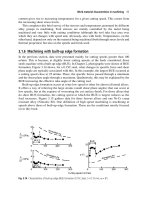
1 The shafts must be parallel, or the life of the chain will be shortened.
The first step is to level the shafts. This is done by placing a level on
each of the shafts, then shimming the low side until the shaft is level.
See Figure 7.4.
2 The next step is to make sure that the shafts are parallel. This is done by
measuring at different points on the shaft and adjusting the shafts until
124 Chain Drives
they are an equal distance apart. Make sure that the shafts are pulled in
as close as possible before performing this procedure. The jacking bolts
can be used to move the shafts apart evenly after the chain is installed.
See Figure 7.5.
3 Before installing a set of used sprockets, verify the size and condition of
the sprockets.
4 Install the sprockets on the shafts following the manufacturer’s recom-
mendations. Locate and install the first sprocket, then use a straightedge
or a string to line the other one up with the one previously installed.
Figure 7.4 Alignment
25" 25"
Figure 7.5 Alignment
Chain Drives 125
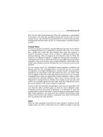
5 Install the chain on the sprockets, then begin increasing the distance
between the sprockets by turning the jacking bolts; do this until the
chain is snug but not tight. To set the proper chain sag, deflect the chain
1
4
" per foot of span between the shafts. Use a string or straightedge and
place it across the top of the chain. Then push down on the chain just
enough to remove the slack. Use a tape measure to measure the amount
of sag. See Figure 7.6.
6 Do a final check for parallel alignment. Remember: the closer the
alignment, the longer the chain will run. See Figure 7.7.
24"
1"
2"
3"
4"
5"
Figure 7.6 Tensioning
Figure 7.7 Final alignment
126 Chain Drives
Power Train Formulas
Shaft Speed
The size of the sprockets in a chain drive system determines the speed
relationship between the drive and driven sprockets. For example, if the
drive sprocket has the same size sprocket as the driven, then the speed will
be equal. See Figure 7.8.
If we change the size of driven sprocket, then the speed of the shaft will also
change. If we know what the speed of the electric motor is, and the size of
the sprockets, we can calculate the speed of the driven shaft by using the
following formula (see Figure 7.9):
Driven shaft rpm =
Drive sprocket # teeth × drive shaft rpm
Driven sprocket # teeth
6T 6T
Driven Drive
1800
rpm
1800
rpm
Figure 7.8 Ratio
12T 6T
Driven Drive
1800
r
p
m
____
r
p
m
Figure 7.9 Speed ratio example
Chain Drives 127
Driven shaft rpm =
6 × 1800
12
900 =
6 × 1800
12
Now we understand how changing the size of a sprocket will also change
the shaft speed. Knowing this, we could also assume that to change the shaft
rpm we must change the sprocket size.
The problem is how do we know the exact size sprocket that we need to
reach the desired speed? Use the same formula that was used to calculate
shaft speed, only switch the location of the driven shaft speed and the driven
sprocket size:
Driven shaft rpm =
Drive sprocket # teeth × drive shaft rpm
Driven sprocket # teeth
Let’s change the problem to look like this:
Driven sprocket teeth =
Drive sprocket # teeth × drive shaft rpm
Driven shaft rpm
Let’s say that we have a problem similar to the ones that we just did, but we
want to change the shaft speed of the driven unit. If we know the speed we
are looking for, we can use the formula above to calculate the sprocket size
required.
Let’s change the speed of the driven shaft to 900 rpm (see Figure 7.10):
12T 6T
Driven Drive
1800
r
p
m
____
r
p
m
Figure 7.10 Sprocket calculations
128 Chain Drives
Driven shaft rpm =
6 × 1800
900
12 =
6 × 1800
900
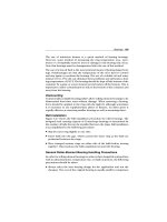
Chain Length
Many times when a mechanic has to change out chains there is no way of
knowing how long the chain should be. One way is to lay the new chain
down beside the old chain, but remember that the old chain has been
stretched.
Or, maybe you are installing a new drive and you want to have the chain
made up before you install it. So what do you do? One method is to
take a tape measure and wrap it around the sprockets to get the chain
length.
However, this is not a very accurate way to determine the length. Instead,
let’s take a couple of measurements, then use a simple formula to calculate
the actual length that is needed.
First, move the sprockets together until they are as close as the adjustments
will allow. Then move the motor or drive out
1
4
of its travel. Now we are
ready to take our measurements. The following information is needed for
an equation to find the chain length:
1 Number of teeth on the drive sprocket.
2 Center-to-center distance between the shafts.
3 The chain pitch in inches.
Now use the following formula to solve the equation (see Figure 7.11):
Chain length =
# teeth drive ×pitch
2
+
# teeth driven ×pitch
2
+ center to center × 2
Chain Drives 129
12T 6T
Driven Drive
35"
40 chain
Figure 7.11 Chain size calculations
Use the formula above to find the chain length.
Chain length =
6×.5
2
+
12×.5
2
+ 35" × 2
74. 5" =
6×.5
2
+
12×.5
2
+ 35" × 2
Multiple Sprockets
When calculating multiple sprocket systems, think of each set of sprockets
as a two-sprocket system.
Chain Speed
In order to calculate the speed of a chain in feet per minute (FPM), we need
the following information:
1 The number of teeth on the sprocket.
2 The shaft rpm of the sprocket.
3 The pitch of the chain in inches.
130 Chain Drives
12T 6T
Driven Drive
1800
rpm
900
rpm
40 chain
Figure 7.12 Speed calculations
With this information we can use the following formula:
FPM =
# teeth × pitch × rpm
12
Use this formula to find the speed of the following chain (see Figure 7.12):
FPM =
# teeth × pitch × rpm
12
450 =
6T × .5" × 1800
12
Chain drives are used to transmit power between a drive unit and a driven
unit. For example, if we have a gearbox and a contact roll on a conveyor,
we need a way to transmit the power from the gearbox to the roll. This can
be done easily and efficiently with a chain drive unit.
Chain drives can consist of one or multiple strand chains, depending on the
load that the unit must transmit. The chains need to be matched with the
sprocket type, and they must be tight enough to prevent slippage.
An effective preventive maintenance program will provide extended life to a
chain drive system, and through proper corrective maintenance procedures,
we can prevent premature failures.
Chain Drives 131
Preventive Maintenance Procedures
Inspection (risk of failures for not following the procedures below is noted
along with a rating): LOW: minimal risk/low chance of failure; MEDIUM:
failure is possible but equipment not operation to specification is highly
probable; HIGH: failure will happen prematurely.
●
Inspect a chain for wear by inspecting the links for worn bushings. If worn
bushings are noted, write a corrective maintenance work order so that
the replacement can be planned and scheduled at a later time.
Risk if the procedure is not followed: HIGH. Chain breakage will occur.
●
Lubricate chain with lightweight oil recommended by chain manufacturer.
(Ask your chain supplier to visit your site and make recommendations
based on documentation they can present to you.)
Risk if the procedure is not followed: HIGH. Chain breakage will occur.
●
Check chain sag. Measure the chain sag using a straight edge or string
and measure the specifications noted on this PM task. (The chain sag
specification can be provided by your chain supplier, or you can use the
procedure noted earlier in this chapter.) WARNING: The specification
must be noted on the PM procedure.
●
Set tension, and make a note at the bottom of the PM work order, if a
deficiency is noted.
Risk if the procedure is not followed: MEDIUM. Sprocket and chain wear
will accelerate, thus causing equipment stoppage.
●
Inspect sprockets for worn teeth and abnormal wear on the sides of the
sprockets. (The question is: Can the sprockets and chain last for two
more weeks without equipment stoppage?) If the sprockets and chain can
last two weeks then write a corrective maintenance work order in order
for this job to be planned and scheduled with the correct parts. If the
sprocket cannot last two weeks, then change all sprockets and the chain.
Set and check sheave and chain alignment and tension. WARNING: When
132 Chain Drives
changing a sprocket, all sprockets, and the chain, should be changed
because the difference between a worn and new sprocket in pitch diam-
eter can be extreme, thus causing premature failure of the sprockets and
chain.
Risk if the procedure is not followed: High. Worn sprockets are an indication
of the equipment being in a failure mode. Action must be taken.
8 Compressors
A compressor is a machine that is used to increase the pressure of a gas or
vapor. They can be grouped into two major classifications: centrifugal and
positive displacement. This section provides a general discussion of these
types of compressors.
Centrifugal
In general, the centrifugal designation is used when the gas flow is radial
and the energy transfer is predominantly due to a change in the centrifugal
forces acting on the gas. The force utilized by the centrifugal compressor is
the same as that utilized by centrifugal pumps.
In a centrifugal compressor, air or gas at atmospheric pressure enters the
eye of the impeller. As the impeller rotates, the gas is accelerated by the
rotating element within the confined space that is created by the volute of
the compressor’s casing. The gas is compressed as more gas is forced into
the volute by the impeller blades. The pressure of the gas increases as it is
pushed through the reduced free space within the volute.
As in centrifugal pumps, there may be several stages to a centrifugal air
compressor. In these multistage units, a progressively higher pressure is
produced by each stage of compression.
Configuration
The actual dynamics of centrifugal compressors are determined by their
design. Common designs are: overhung or cantilever, centerline, and
bullgear.
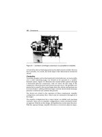
Overhung or Cantilever
The cantilever design is more susceptible to process instability than cen-
terline centrifugal compressors. Figure 8.1 illustrates a typical cantilever
design.
The overhung design of the rotor (i.e., no outboard bearing) increases the
potential for radical shaft deflection. Any variation in laminar flow, volume,