Industrial Machinery Repair Part Episode 2 Part 6 potx
Bạn đang xem bản rút gọn của tài liệu. Xem và tải ngay bản đầy đủ của tài liệu tại đây (337.78 KB, 25 trang )
Mixers and Agitators 359
is acceptable for each application. The recommended range should include
adjustments for temperature, flow rates, mixing speeds, and other factors
that directly or indirectly affect viscosity.
Troubleshooting
Table 18.1 identifies common failure modes and their causes for mixers
and agitators. Most of the problems that affect performance and reliability
are caused by improper installation or variations in the product’s physical
properties.
Table 18.1 Common failure modes of mixers and agitators
THE PROBLEM
THE CAUSES
Surface vortex visible
Incomplete mixing of product
Excessive vibration
Excessive wear
Motor overheats
Excessive power demand
Excessive bearing failures
Abrasives in product •
Mixer/agitator setting too close to side or
corner
• • • • •
Mixer/agitator setting too high • •
Mixer/agitator setting too low • •
Mixer/agitator shaft too long
•
Product temperature too low
• • •
Rotating element imbalanced or
damaged
• • • • •
Speed too high • • •
Speed too low •
Viscosity/specific gravity too high
• • •
Wrong direction of rotation • • •
360 Mixers and Agitators
Proper installation of mixers and agitators is critical. The physical location of
the vanes or propellers within the vessel is the dominant factor to consider.
If the vanes are set too close to the side, corner, or bottom of the vessel,
a stagnant zone will develop that causes both loss of mixing quality and
premature damage to the equipment. If the vanes are set too close to the
liquid level, vortexing can develop. This will also cause a loss of efficiency
and accelerated component wear.
Variations in the product’s physical properties, such as viscosity, also will
cause loss of mixing efficiency and premature wear of mixer components.
Although the initial selection of the mixer or agitator may have addressed the
full range of physical properties that will be encountered, applications some-
times change. Such a change may result in the use of improper equipment
for a particular application.
19 Packing and Seals
All machines such as pumps and compressors that handle liquids or gases
must include a reliable means of sealing around their shafts so that the
fluid being pumped or compressed does not leak. To accomplish this, the
machine design must include a seal located at various points to prevent
leakage between the shaft and housing. In order to provide a full under-
standing of seal and packing use and performance, this manual discusses
fundamentals, seal design, and installation practices.
Fundamentals
Shaft seal requirements and two common types of seals, packed stuffing
boxes and simple mechanical seals, are described and discussed in this sec-
tion. A packed box typically is used on slow- to moderate-speed machinery
where a slight amount of leakage is permissible. A mechanical seal is used
on centrifugal pumps or other type of fluid handling equipment where shaft
sealing is critical.
Shaft Seal Requirements
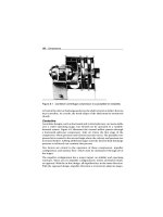
Figure 19.1 shows the cross-section of a typical end-suction centrifugal
pump where the fluid to be pumped enters the suction inlet at the eye of
the impeller. Due to the relatively high speed of rotation, the fluid collected
within the impeller vanes is held captive because of the close tolerance
between the front face of the impeller and the pump housing.
With no other available escape route, the fluid is passed to the outside
of the impeller by centrifugal force and into the volute, where its kinetic
energy is converted into pressure. At the point of discharge (i.e., discharge
nozzle), the fluid is highly pressurized compared to its pressure at the inlet
nozzle of the pump. This pressure drives the fluid from the pump and
allows a centrifugal pump to move fluids to considerable heights above the
centerline of the pump.
This highly pressurized fluid also flows around the impeller to a lower pres-
sure zone where, without an adequate seal, the fluid will leak along the drive
362 Packing and Seals
Discharge
Housing
Suction
Back-head
Impeller
Shaft
Balancing holes
Pumping vanes
Figure 19.1 Cross-section of a typical end-suction centrifugal pump
shaft to the outside of the pump housing. The lower pressure results from a
pump design intended to minimize the pressure behind the impeller. Note
that this design element is specifically aimed at making drive shaft sealing
easier.
Reducing the pressure acting on the fluid behind the impeller can be
accomplished by two different methods, or a combination of both, on an
open-impeller unit. One method is where small pumping vanes are cast on
the backside of the impeller. The other method is for balance holes to be
drilled through the impeller to the suction eye.
In addition to reducing the driving force behind shaft leakage, decreasing
the pressure differential between the front and rear of the impeller using one
or both of the methods described above greatly decreases the axial thrust
on the drive shaft. This decreased pressure prolongs the thrust bearing life
significantly.
Sealing Devices
Two sealing devices are described and discussed in this section: packed
stuffing boxes and simple mechanical seals.
Packing and Seals 363
Packed Stuffing Boxes
Before the development of mechanical seals, a soft pliable material or pack-
ing placed in a box and compressed into rings encircling the drive shaft
was used to prevent leakage. Compressed packing rings between the pump
housing and the drive shaft, accomplished by tightening the gland-stuffing
follower, formed an effective seal.
Figure 19.2 shows a typical packed box that seals with rings of compressed
packing. Note that if this packing is allowed to operate against the shaft with-
out adequate lubrication and cooling, frictional heat eventually builds up to
A. Packing chamber
or box
B. Packing rings
C. Gland follower
or stuffin
g
g
land
Figure 19.2 Typical packed stuffing box
364 Packing and Seals
the point of total destruction of the packing and damage to the drive shaft.
Therefore, all packed boxes must have a means of lubrication and cooling.
Lubrication and cooling can be accomplished by allowing a small amount
of leakage of fluid from the machine or by providing an external source of
fluid. When leakage from the machine is used, leaking fluid is captured in
collection basins that are built into the machine housing or baseplate. Note
that periodic maintenance to recompress the packing must be carried out
when leakage becomes excessive.
Packed boxes must be protected against ingress of dirt and air, which can
result in loss of resilience and lubricity. When this occurs, packing will act
like a grinding stone, effectively destroying the shaft’s sacrificial sleeve, and
cause the gland to leak excessively. When the sacrificial sleeve on the drive
shaft becomes ridged and worn, it should be replaced as soon as possi-
ble. In effect, this is a continuing maintenance program that can readily be
measured in terms of dollars and time.
Uneven pressures can be exerted on the drive shaft due to irregularities in
the packing rings, resulting in irregular contact with the shaft. This causes
uneven distribution of lubrication flow at certain locations, producing acute
wear and packed-box leakages. The only effective solution to this problem
is to replace the shaft sleeve or drive shaft at the earliest opportunity.
Simple Mechanical Seal
Mechanical seals, which are typically installed in applications where no
leakage can be tolerated, are described and discussed in this section.
Toxic chemicals and other hazardous materials are primary examples of
applications where mechanical seals are used.
Components and Assembly
Figure 19.3 shows the components of a simple mechanical seal, which is
made up of the following:
●
Coil spring
●
O-ring shaft packing
●
Seal ring
The seal ring fits over the shaft and rotates with it. The spring must be
made from a material that is compatible with the fluid being pumped so
that it will withstand corrosion. Likewise, the same care must be taken in
Packing and Seals 365
Stationary ring
Rotating ring
Pressure
chamber
Static seal point
stationary unit
to housing
Static seal point
rotating unit
to shaft
Rotary seal point
mating ring faces
in contact
Rotating shaft
Force
Force
Figure 19.3 Simple mechanical seal
material selection of the O-ring and seal materials. The insert and insert
O-ring mounting are installed in the bore cavity provided in the gland ring.
This assembly is installed in a pump-stuffing box, which remains stationary
when the pump shaft rotates.
A carbon graphite insertion ring provides a good bearing surface for the seal
ring to rotate against. It is also resistive to attack by corrosive chemicals over
a wide range of temperatures.
Figure 19.4 depicts a simple seal that has been installed in the pump’s
stuffing box. Note how the coil spring sits against the back of the pump’s
impeller, pushing the packing O-ring against the seal ring. By doing so, it
remains in constant contact with the stationary insert ring.
As the pump shaft rotates, the shaft packing rotates with it due to friction.
(In more complex mechanical seals, the shaft-packing element is secured to
the rotating shaft by Allen screws.) There is also friction between the spring,
the impeller, and the compressed O-ring. Thus, the whole assembly rotates
together when the pump shaft rotates. The stationary insert ring is located
within the gland bore. The gland itself is bolted to the face of the stuffing
box. This part is held stationary due to the friction between the O-ring insert
mounting and the inside diameter (ID) of the gland bore as the shaft rotates
within the bore of the insert.
366 Packing and Seals
Figure 19.4 Pump stuffing box seal
How It Prevents Leakage
Having discussed how a simple mechanical seal is assembled in the stuffing
box, we must now consider how the pumped fluid is stopped from leaking
out to the atmosphere.
In Figure 19.4, the O-ring shaft packing blocks the path of the fluid along
the drive shaft. Any fluid attempting to pass through the seal ring is stopped
by the O-ring shaft packing. Any further attempt by the fluid to pass through
the seal ring to the atmospheric side of the pump is prevented by the gland
gasket and the O-ring insert. The only other place where fluid can poten-
tially escape is the joint surface, which is between the rotating carbon ring
and the stationary insert. (Note: The surface areas of both rings must be
machined-lapped perfectly flat, measured in light bands with tolerances of
one-millionth of an inch.)
Sealing Area and Lubrication
The efficiency of all mechanical seals is dependent upon the condition of the
sealing area surfaces. The surfaces remain in contact with each other for the
effective working life of the seal and are friction-bearing surfaces.
As in the compressed packing gland, lubrication also must be provided in
mechanical seals. The sealing area surfaces should be lubricated and cooled
Packing and Seals 367
with pumped fluid (if it is clean enough) or an outside source of clean fluid.
However, much less lubrication is required with this type of seal because the
frictional surface area is smaller than that of a compressed packing gland,
and the contact pressure is equally distributed throughout the interface. As
a result, a smaller amount of lubrication passes between the seal faces to
exit as leakage.
In most packing glands there is a measurable flow of lubrication fluid
between the packing rings and the shaft. With mechanical seals, the faces
ride on a microscopic film of fluid that migrates between them, resulting
in leakage. However, leakage is so slight that if the temperature of the fluid
is above its saturation point at atmospheric pressure, it flashes off to vapor
before it can be visually detected.
Advantages and Disadvantages
Mechanical seals offer a more reliable seal than compressed packing seals.
Because the spring in a mechanical seal exerts a constant pressure on the
seal ring, it automatically adjusts for wear at the faces. Thus, the need for
manual adjustment is eliminated. Additionally, because the bearing surface
is between the rotating and stationary components of the seal, the shaft or
shaft sleeve does not become worn. Although the seal will eventually wear
out and need replacing, the shaft will not experience wear.
However, much more precision and attention to detail must be given to
the installation of mechanical seals compared to conventional packing.
Nevertheless, it is not unusual for mechanical seals to remain in service for
many thousands of operational hours if they have been properly installed
and maintained.
Mechanical Seal Designs
Mechanical seal designs are referred to as friction drives, or single-coil spring
seals, and positive drives.
Single-Coil Spring Seal
The seal shown back in Figure 19.4 depicts a typical friction drive or single-
coil spring seal unit. This design is limited in its use because the seal relies
on friction to turn the rotary unit. Because of this, its use is limited to liquids
such as water or other nonlubricating fluids. If this type of seal is to be used
368 Packing and Seals
with liquids that have natural lubricating properties, it must be mechanically
locked to the drive shaft.
Although this simple seal performs its function satisfactorily, there are two
drawbacks that must be considered. Both drawbacks are related to the use
of a coil spring that is fitted over the drive shaft:
●
One drawback of the spring is the need for relatively low shaft speeds
because of a natural tendency of the components to distort at high surface
speeds. This makes the spring push harder on one side of the seal than
the other, resulting in an uneven liquid film between the faces. These
cause excessive leakage and wear at the seal.
●
The other drawback is simply one of economics. Because pumps come
in a variety of shaft sizes and speeds, the use of this type of seal requires
inventorying several sizes of spare springs, which ties up capital.
Nevertheless, the simple and reliable coil spring seal has proven itself in
the pumping industry and is often selected for use despite its drawbacks.
In regulated industries, this type of seal design far exceeds the capabilities
of a compressed packing ring seal.
Positive Drive
There are two methods of converting a simple seal to positive drive. Both
methods, which use collars secured to the drive shaft by setscrews, are
shown in Figure 19.5. In this figure, the end tabs of the spring are bent at
Figure 19.5 Conversion of a simple seal to positive drive
Packing and Seals 369
90 degrees to the natural curve of the spring. These end tabs fit into notches
in both the collar and the seal ring. This design transmits rotational drive
from the collar to the seal ring by the spring. Figure 19.5 also shows two
horizontally mounted pins that extend over the spring from the collar to
the seal ring.
Installation Procedures
This section describes the installation procedures for packed stuffing boxes
and mechanical seals.
Packed Stuffing Box
This procedure provides detailed instructions on how to repack centrifugal
pump packed stuffing boxes or glands. The methodology described here
is applicable to other gland sealed units such as valves and reciprocating
machinery.
Tool List
The following is a list of the tools needed to repack a centrifugal pump
gland:
●
Approved packing for specific equipment
●
Mandrel sized to shaft diameter
●
Packing ring extractor tool
●
Packing board
●
Sharp knife
●
Approved cleaning solvent
●
Lint-free cleaning rags
Precautions
The following precautions should be taken in repacking a packed stuffing
box:
●
Ensure coordination with operations control.
●
Observe site and area safety precautions at all times.
370 Packing and Seals
●
Ensure equipment has been electrically isolated and suitably locked out
and tagged.
●
Ensure machine is isolated and depressurized, with suction and discharge
valves chained and locked shut.
Installation
The following are the steps to follow in installing a gland:
1 Loosen and remove nuts from the gland bolts.
2 Examine threads on bolts and nuts for stretching or damage. Replace if
defective.
3 Remove the gland follower from the stuffing box and slide it along the
shaft to provide access to the packing area.
4 Use packing extraction tool to carefully remove packing from the gland.
5 Keep the packing rings in the order they are extracted from the gland
box. This is important in evaluating wear characteristics. Look for rub
marks and any other unusual markings that would identify operational
problems.
6 Carefully remove the lantern ring. This is a grooved, bobbin-like spool
piece that is situated exactly on the centerline of the seal water inlet
connection to the gland (Figure 19.6).
NOTE: It is most important to place the lantern ring under the seal water
inlet connection to ensure the water is properly distributed within the
gland to perform its cooling and lubricating functions.
Figure 19.6 Lantern ring or seal cage
Packing and Seals 371
7 Examine the lantern ring for scoring and possible signs of crushing. Make
sure the lantern ring’s outside diameter (OD) provides a sliding fit with
the gland box’s internal dimension. Check that the lantern ring’s ID is a
free fit along the pump’s shaft sleeve. If the lantern ring does not meet
this simple criterion, replace it with a new one.
8 Continue to remove the rest of the packing rings as previously described.
Retain each ring in the sequence that it was removed for examination.
9 Do not discard packing rings until they have been thoroughly examined
for potential problems.
10 Turn on the gland seal cooling water slightly to ensure there is no
blockage in the line. Shut the valve when good flow conditions are
established.
11 Repeat Steps 1 through 10 with the other gland box.
12 Carefully clean out the gland stuffing boxes with a solvent-soaked rag to
ensure that no debris is left behind.
13 Examine the shaft sleeve in both gland areas for excessive wear caused
by poorly lubricated or overtightened packing.
NOTE: If the shaft sleeve is ridged or badly scratched in any way, the split
housing of the pump may have to be split and the impeller removed for
the sleeve to be replaced. Badly installed and maintained packing causes
this.
14 Check total indicated runout (TIR) of the pump shaft by placing a mag-
netic base-mounted dial indicator on the pump housing and a dial stem
on the shaft. Zero the dial and rotate the pump shaft one full turn. Record
reading (Figure 19.7).
NOTE: If the TIR is greater than +/−0. 002 inches, the pump shaft should
be straightened.
15 Determine the correct packing size before installing using the following
method (Figure 19.8):
Measure the ID of the stuffing box, which is the OD at the packing (B),
and the diameter of the shaft (A). With this data, the packing cross-
section size is calculated by:
Packing Cross Section =
B − A
2
372 Packing and Seals
Indicator
Figure 19.7 Dial indicator check for run-out
Cross section
BϪA
2
Determine the correct
cross sections:
OD (A)
OD (B)
Ϫ
Figure 19.8 Selecting correct packing size
The packing length is determined by calculating the circumference of
the packing within the stuffing box. The centerline diameter is calcu-
lated by adding the diameter of the shaft to the packing cross-section
that was calculated in the preceding formula. For example, a stuffing
box with a 4" ID and a shaft with a 2" diameter will require a pack-
ing cross-section of 1". The centerline of the packing would then be 3".
Packing and Seals 373
Therefore, the approximate length of each piece of packing would be:
Packing Length = Centerline Diameter × 3.1416
= 3. 0 ×3.1416 = 9.43 inches
The packing should be cut approximately
1
4
" longer than the calculated
length so that the end can be bevel cut.
16 Controlled leakage rates easily can be achieved with the correct size
packing.
17 Cut the packing rings to size on a wooden mandrel that is the same
diameter as the pump shaft. Rings can be cut either square (butt cut)
or diagonally (approximately 30 degrees). NOTE: Leave at least a
1
6
"
gap between the butts regardless of the type of cut used. This permits
the packing rings to move under compression or temperature without
binding on the shaft surface.
18 Ensure that the gland area is perfectly clean and is not scratched in any
way before installing the packing rings.
19 Lubricate each ring lightly before installing in the stuffing box. NOTE:
When putting packing rings around the shaft, use an “S” twist. Do not
bend open. See Figure 19.9.
20 Use a split bushing to install each ring, ensuring that the ring bottoms
out inside the stuffing box. An offset tamping stick may be used if a split
bushing is not available. Do not use a screwdriver.
“S” Twist
Wrong
Figure 19.9 Proper and improper installation of packing
374 Packing and Seals
Figure 19.10 Stagger butt joints
1/8" to 3/16"
Figure 19.11 Proper gland follower clearance
21 Stagger the butt joints, placing the first ring butt at 12 o’clock; the second
at 6 o’clock; the third at 3 o’clock; the fourth at 9 o’clock; etc., until the
packing box is filled (Figure 19.10). NOTE: When the last ring has been
installed, there should be enough room to insert the gland follower
1
8
to
3/16 inches into the stuffing box (Figure 19.11).
22 Install the lantern ring in its correct location within the gland. Do not
force the lantern ring into position (Figure 19.12).
23 Tighten up the gland bolts with a wrench to seat and form the packing
to the stuffing box and shaft.
Packing and Seals 375
Figure 19.12 Proper lantern ring installation
24 Loosen the gland nuts one complete turn and rotate the shaft by hand
to get running clearance.
25 Retighten the nuts finger tight only. Again, rotate the shaft by hand to
make sure the packing is not too tight.
26 Contact operations to start the pump and allow the stuffing box to leak
freely. Tighten the gland bolts one flat at a time until the desired leakage
is obtained and the pump runs cool.
376 Packing and Seals
27 Clean up the work area and account for all tools before returning them
to the tool crib.
28 Inform operations of project status and complete all paperwork.
29 After the pump is in operation, periodically inspect the gland to deter-
mine its performance. If it tends to leak more than the allowable amount,
tighten by turning the nuts one flat at a time. Give the packing enough
time to adjust before tightening it more. If the gland is tightened too
much at one time, the packing can be excessively compressed, causing
unnecessary friction and subsequent burnout of the packing.
Mechanical Seals
A mechanical seal’s performance depends on the operating condition of
the equipment where it is installed. Therefore, inspection of the equipment
before seal installation can potentially prevent seal failure and reduce overall
maintenance expenses.
Equipment Checkpoints
The pre-installation equipment inspection should include the following:
stuffing box space, lateral or axial shaft movement (end play), radial shaft
movement (whip or deflection), shaft runout (bent shaft), stuffing box face
squareness, stuffing box bore concentricity, driver alignment, and pipe
strain.
Stuffing Box Space
To properly receive the seal, the radial space and depth of the stuffing
box must be the same as the dimensions shown on the seal assembly
drawing.
Lateral or Axial Shaft Movement (Endplay)
Install a dial indicator with the stem against the shoulder of the shaft. Use
a soft hammer or mallet to lightly tap the shaft on one end and then on the
other. Total indicated endplay should be between 0.001 and 0.004 inches. A
mechanical seal cannot work properly with a large amount of endplay or lat-
eral movement. If the hydraulic condition changes (as frequently happens),
the shaft could “float,” resulting in sealing problems. Minimum endplay is
a desirable condition for the following reasons:
●
Excessive endplay can cause pitting, fretting, or wear at the point of
contact between the shaft packing in the mechanical seal and the shaft
Packing and Seals 377
or sleeve O.D. As the mechanical seal-driving element is locked to the
shaft or sleeve, any excessive endplay will result in either overloading or
underloading of the springs, causing excessive wear or leaks.
●
Excessive endplay as a result of defective thrust bearings can reduce seal
performance by disturbing both the established wear pattern and the
lubricating film.
●
A floating shaft can cause chattering, which results in chipping of the seal
faces, especially the carbon element. Ideal mechanical seal performance
requires a uniform wear pattern and a liquid film between the mating
contact faces.
Radial Shaft Movement (Whip or Deflection)
Install the dial indicator as close to the radial bearing as possible. Lift the
shaft or exert light pressure at the impeller end. If more than 0.002 to
0.003 inches of radial movement occurs, investigate bearings and bearing
fits (especially the bore) for the radial bearing fit. An oversized radial bearing
bore caused by wear, improper machining, or corrosion will cause excessive
radial shaft movement resulting in shaft whip and deflection. Minimum
radial shaft movement is important for the following reasons:
●
Excessive radial movement can cause wear, fretting, or pitting of the shaft
packing or secondary sealing element at the point of contact between the
shaft packing and the shaft or sleeve OD.
●
Extreme wear at the mating contact faces will occur when excessive shaft
whip or deflection is present due to defective radial bearings or bearing
fits. The contact area of the mating faces will be increased, resulting in
increased wear and the elimination or reduction of the lubricating film
between the faces, further shortening seal life.
Shaft Runout (Bent Shaft)
A bent shaft can lead to poor sealing and cause vibration. Bearing life is
greatly reduced, and the operating conditions of both radial and thrust
bearings can be affected.
Clamp the dial indicator to the pump housing and measure the shaft
runout at two or more points on the OD of the impeller end of the
shaft. Also measure the shaft runout at the coupling end of the shaft. If
the runout exceeds 0.002 inches, remove the shaft and straighten or
replace it.
378 Packing and Seals
Square Stuffing Box Face
With the pump stuffing box cover bolted down, clamp the dial indicator
to the shaft with the stem against the face of the stuffing box. The total
indicator runout should not exceed 0.003 inches.
When the face of the stuffing box is “out-of-square,” or not perpendicular
to the shaft axis, the result can be serious malfunction of a mechanical seal
for the following reasons:
●
The stationary gland plate that holds the stationary insert or seat in posi-
tion is bolted to the face of the stuffing box. Misalignment will cause the
gland to cock, resulting in cocking of the stationary element. This results
in seal wobble or operation in an elliptical pattern. This condition is a
major factor in fretting, pitting, and wearing of the mechanical seal shaft
packing at the point of contact with the shaft or sleeve.
●
A seal that is wobbling on the shaft can also cause wear on the drive pins.
Erratic wear on the face contact causes poor seal performance.
Stuffing Box Bore Concentricity
With the dial indicator set up as described above, place the indicator stem
well into the bore of the stuffing box. The stuffing box should be concentric
to the shaft axis to within a 0.005-inch total indicator reading.
Eccentricity alters the hydraulic loading of the seal faces, reducing seal life
and performance. If the shaft is eccentric to the box bore, check the slop,
or looseness, in the pump bracket fits. Rust, atmospheric corrosion, or
corrosion from leaking gaskets can cause damage to these fits, making it
impossible to ensure a stuffing box that is concentric with the shaft. A possi-
ble remedy for this condition is welding the corroded area and remachining
to proper dimensions.
Driver Alignment and Pipe Strain
Driver alignment is extremely important, and periodic checks should be
performed. Pipe strain can also damage pumps, bearings, and seals.
In most plants, it is customary to blind the suction and discharge flanges of
inactive pumps. These blinds should be removed before the pump driver
alignment is made, or the alignment job is incomplete.
After the blinds have been removed and as the flanges on the suction
and discharge are being connected to the piping, check the dial indica-
tor reading on the outside diameter (OD) of the coupling half and observe
Packing and Seals 379
movement of the indicator dial as the flanges are being secured. Deviation
indicates pipe strain. If severe strain exists, corrective measures should
be taken, or damage to the pump and unsatisfactory seal service can
result.
Seal Checkpoints
The following are important seal checkpoints:
●
Ensure that all parts are kept clean, especially the running faces of the
seal ring and insert.
●
Check the seal rotary unit, and make sure the drive pins and spring pins
are free in the pinholes or slots.
●
Check the setscrews in the rotary unit collar to see that they are free in
the threads. Setscrews should be replaced after each use.
●
Check the thickness of all gaskets against the dimensions shown on the
assembly drawing. Improper gasket thickness will affect the seal setting
and the spring load imposed on the seal.
●
Check the fit of the gland ring to the equipment. Make sure there is no
interference or binding on the studs or bolts or other obstructions. Be
sure the gland ring pilot, if any, enters the bore with a reasonable guiding
fit for proper seal alignment.
●
Make sure all rotary unit parts of the seal fit over the shaft freely.
●
Check both running faces of the seal (seal ring and insert) and be sure
there are no nicks or scratches. Imperfections of any kind on either of
these faces will cause leaks.
Installing the Seal
The following steps should be taken when installing a seal:
●
Instruction booklets and a copy of the assembly drawing are shipped
with each seal. Be sure each is available, and read the instructions before
starting installation.
●
Remove all burrs and sharp edges from the shaft or shaft sleeve, including
sharp edges of keyways and threads. Worn shafts or sleeves should be
replaced.
●
Check the stuffing box bore and face to ensure they are clean and free of
burrs.
380 Packing and Seals
●
The shaft or sleeve should be lightly oiled before the seal is assembled
to allow the seal parts to move freely over it. This is especially desirable
when assembling the seal collar because the bore of the collar usually
has only a few thousandths of an inch clearance. Care should be taken to
avoid getting the collar cocked.
●
Install the rotary unit parts on the shaft or sleeve in the proper order.
●
Be careful when passing the seal gland ring and insert over the shaft. Do
not bring the insert against the shaft because it might chip away small
pieces from the edge of the running face.
●
Wipe the seal faces clean and apply a clean oil film before completing the
equipment assembly. A clean finger, which is not apt to leave lint, will do
the best job when giving the seal faces the final wiping.
●
Complete the equipment assembly, taking care when compressing the
seal into the stuffing box.
●
Seat the gland ring and gland ring gasket to the face of the stuffing box
by tightening the nuts or bolts evenly and firmly. Be sure the gland
ring is not cocked. Tighten the nuts or bolts only enough to affect a
seal at the gland ring gasket, usually finger tight and
1
2
to
3
4
of a turn
with a wrench. Excessively tightening the gland ring nut or bolt will
cause distortion that will be transmitted to the running face, resulting in
leaks.
If the seal assembly drawing is not available, the proper seal setting
dimension for inside seals can be determined as follows:
●
Establish a reference mark on the shaft or sleeve flush with the face of the
stuffing box.
●
Determine how far the face of the insert will extend into the stuffing box
bore. This dimension is taken from the face of the gasket.
●
Determine the compressed length of the rotary unit by compressing the
rotary unit to the proper spring gap.
●
This dimension added to the distance the insert extends into the stuffing
box will give the seal setting dimension from the reference mark on the
shaft or sleeve to the back of the seal collar.
●
Outside seals are set with the spring gap equal to the dimension stamped
on the seal collar.
Packing and Seals 381
●
Cartridge seals are set at the factory and installed as complete assemblies.
These assemblies contain spacers that must be removed after the seal
assembly is bolted into position and the sleeve collar is in place.
Installation of Environmental Controls
Mechanical seals are often chosen and designed to operate with environ-
mental controls. If this is the case, check the seal assembly drawing or
equipment drawing to ensure that all environmental control piping is prop-
erly installed. Before equipment startup, all cooling and heating lines should
be operating and remain so for at least a short period after equipment
shutdown.
Before startup, all systems should be properly vented. This is especially
important on vertical installations where the stuffing box is the uppermost
portion of the pressure-containing part of the equipment. The stuffing box
area must be properly vented to avoid a vapor lock in the seal area that
would cause the seal to run dry.
On double seal installations, be sure the sealing liquid lines are connected,
the pressure control valves are properly adjusted, and the sealing liquid
system is operating before starting the equipment.
Seal Startup Procedures
When starting equipment with mechanical seals, make sure the seal faces
are immersed in liquid from the beginning so they will not be damaged
from dry operation. The following recommendations for seal startup apply
to most types of seal installations and will improve seal life if followed:
●
Caution the electrician not to run the equipment dry while checking
motor rotation. A slight turnover will not hurt the seal, but operating full
speed for several minutes under dry conditions will destroy or severely
damage the rubbing faces.
●
The stuffing box of the equipment, especially centrifugal pumps, should
always be vented before startup. Even though the pump has a flooded
suction, it is still possible that air may be trapped in the top of the stuffing
box after the initial liquid purge of the pump.
●
Check installation for need of priming. Priming might be necessary in
applications with a low or negative suction head.
●
Where cooling or bypass recirculation taps are incorporated in the seal
gland, piping must be connected to or from these taps before startup.
382 Packing and Seals
These specific environmental control features must be used to protect
the organic materials in the seal and to ensure its proper performance.
Cooling lines should be left open at all times or whenever possible.
This is especially true when a hot product might be passing through
standby equipment while it is not online. Many systems provide for prod-
uct to pass through the standby equipment, so the need for additional
product volume or an equipment change is only a matter of pushing a
button.
●
With hot operational equipment that is shut down at the end of each day,
it is best to leave the cooling water on at least long enough for the seal
area to cool below the temperature limits of the organic materials in the
seal.
●
Face lubricated-type seals must be connected from the source of lubri-
cation to the tap openings in the seal gland before startup. This is
another predetermined environmental control feature that is mandatory
for proper seal function. Where double seals are to be operated, it is nec-
essary that the lubrication feed lines be connected to the proper ports for
both circulatory or dead-end systems before equipment startup. This is
very important because all types of double seals depend on the controlled
pressure and flow of the sealing fluid to function properly. Even before
the shaft is rotated, the sealing liquid pressure must exceed the product
pressure opposing the seal. Be sure a vapor trap does not prevent the
lubricant from reaching the seal face promptly.
●
Thorough warm-up procedures include a check of all steam piping
arrangements to be sure that all are connected and functioning, as prod-
ucts that will solidify must be fully melted before startup. It is advisable to
leave all heat sources on during shutdown to ensure a liquid condition of
the product at all times. Leaving the heat on at all times further facilitates
quick startups and equipment switchovers that may be necessary during
a production cycle.
●
Thorough chilling procedures are necessary on some installations, espe-
cially liquefied petroleum gases (LPG) applications. LPG must always be
kept in a liquid state in the seal area, and startup is usually the most critical
time. Even during operation, the re-circulation line piped to the stuffing
box might have to be run through a cooler in order to overcome frictional
heat generated at the seal faces. LPG requires a stuffing box pressure that
is greater than the vapor pressure of the product at pumping temperature
(25 to 50 psi differential is desired).
Packing and Seals 383
Troubleshooting
Failure modes that affect shaft seals are normally limited to excessive leakage
and premature failure of the mechanical seal or packing. Table 19.1 lists the
common failure modes for both mechanical seals and packed boxes. As the
table indicates, most of these failure modes can be directly attributed to
misapplication, improper installation, or poor maintenance practices.
Mechanical Seals
By design, mechanical seals are the weakest link in a machine train. If there is
any misalignment or eccentric shaft rotation, the probability of a mechanical
seal failure is extremely high. Most seal tolerances are limited to no more
than 0.002 inches of total shaft deflection or misalignment. Any deviation
outside of this limited range will cause catastrophic seal failure.
Physical misalignment of a shaft will either cause seal damage, permitting
some leakage through the seal, or it will result in total seal failure. Therefore,
it is imperative that good alignment practices be followed for all shafts that
have an installed mechanical seal.
Process and machine-induced shaft instability also create seal problems.
Primary causes for this failure mode include: aerodynamic or hydraulic
instability, critical speeds, mechanical imbalance, process load changes, or
radical speed changes. These can cause the shaft to deviate from its true
centerline enough to result in seal damage.
Chemical attack (i.e., corrosion or chemical reaction with the liquid being
sealed) is another primary source of mechanical seal problems. Generally,
two primary factors cause chemical attack: misapplication or improper
flushing of the seal.
Misapplication is another major cause of premature seal failure. Little atten-
tion is generally given to the selection of mechanical seals. Most plants rely
on the vendor to provide a seal that is compatible with the application. Too
often there is a serious breakdown in communications between the end user
and the vendor on this subject. Either the procurement specification does
not provide the vendor with appropriate information, or the vendor does
not offer the option of custom ordering the seals. Regardless of the reason,
mechanical seals are often improperly selected and used in inappropriate
applications.