Inspection Evaluation And Repair Of Steel structures Part 1 docx
Bạn đang xem bản rút gọn của tài liệu. Xem và tải ngay bản đầy đủ của tài liệu tại đây (388.9 KB, 10 trang )
US Army Corps
of Engineers®
ENGINEERING AND DESIGN
Inspection, Evaluation, and Repair
of Hydraulic Steel Structures
EM 1110-2-6054
1 December 2001
ENGINEER MANUAL
AVAILABILITY
Electronic copies of this and other U.S. Army Corps of
Engineers (USACE) publications are available on the Internet at
This site is the
only repository for all official USACE engineer regulations,
circulars, manuals, and other documents originating from
HQUSACE. Publications are provided in portable document
format (PDF).
DEPARTMENT OF THE ARMY
EM 1110-2-6054
U.S. Army Corps of Engineers
CECW-ED
Washington, DC 20314-1000
Manual
No. 1110-2-6054 1 December 2001
Engineering and Design
INSPECTION, EVALUATION AND REPAIR OF HYDRAULIC STEEL STRUCTURES
1. Purpose. This manual describes the inspection, evaluation, and repair of hydraulic steel structures,
including preinspection identification of critical locations (such as fracture critical members and various
connections) that require close examination. Nondestructive testing techniques that may be used during
periodic inspections or detailed structural inspections are discussed. Guidance is provided on material
testing to determine the chemistry, strength, ductility, hardness, and toughness of the base and weld metal.
Analyses methods that can be used to determine structure safety, safe inspection intervals, and expected
remaining life of the structure with given operational demands are presented. Finally, considerations for
various types of repair are discussed.
2. Applicability. This manual applies to all USACE commands having responsibilities for the design
of civil works projects.
3. Distribution Statement. Approved for public release; distribution is unlimited.
4. Scope of the Manual. Chapter 1 describes the types of hydraulic steel structures. Chapter 2
discusses the causes of structural deterioration. Chapter 3 describes periodic inspection procedures,
which are primarily visual. If the inspection indicates that a structure is distressed, nondestructive or
destructive testing, described in Chapters 4 and 5, respectively, may be required. Chapter 6 describes the
evaluation of the capability of a structure to perform its intended function. Chapter 7 discusses the
determination of fracture toughness, and Chapter 8 describes repairs.
FOR THE COMMANDER:
1 Appendix ROBERT CREAR
(See Table of Contents) Colonel, Corps of Engineers
Chief of Staff
This manual supersedes ETL 1110-2-346, 30 September 1993, and ETL 1110-2-351, 31 March 1994.
DEPARTMENT OF THE ARMY
EM 1110-2-6054
U.S. Army Corps of Engineers
CECW-ED
Washington, DC 20314-1000
Manual
No. 1110-2-6054 1 December 2001
Engineering and Design
INSPECTION, EVALUATION AND REPAIR OF HYDRAULIC STEEL STRUCTURES
Subject Paragraph Page
Chapter 1
Introduction
Purpose 1-1 1-1
Applicability 1-2 1-1
Distribution 1-3 1-1
References 1-4 1-1
Background 1-5 1-1
Mandatory Requirements 1-6 1-4
Chapter 2
Causes of Structural Deterioration
Corrosion 2-1 2-1
Fracture 2-2 2-3
Fatigue 2-3 2-5
Design Deficiencies 2-4 2-14
Fabrication Discontinuities 2-5 2-15
Operation and Maintenance 2-6 2-15
Unforeseen Loading 2-7 2-16
Chapter 3
Periodic Inspection
Purpose of Inspection 3-1 3-1
Inspection Procedures 3-2 3-1
Critical Members and Connections 3-3 3-2
Visual Inspection 3-4 3-13
Critical Area Checklist 3-5 3-13
Inspection Intervals 3-6 3-14
Chapter 4
Detailed Inspection
Introduction 4-1 4-1
Purpose of Inspection 4-2 4-1
Inspection Procedures 4-3 4-1
Inspector Qualifications 4-4 4-5
Summary of NDT Methods 4-5 4-6
Discontinuity Acceptance Criteria for Weldments 4-6 4-8
i
EM 1110-2-6054
1 Dec 01
Subject Paragraph Page
Chapter 5
Material and Weld Testing
Purpose of Testing 5-1 5-1
Selection of Samples from Existing Structure 5-2 5-1
Chemical Analysis 5-3 5-1
Tension Test 5-4 5-1
Bend Test 5-5 5-2
Fillet Weld Shear Test 5-6 5-3
Hardness Test 5-7 5-3
Fracture Toughness Test 5-8 5-4
Chapter 6
Structural Evaluation
Purpose of Evaluation 6-1 6-1
Fracture Behavior of Steel Materials 6-2 6-1
Fracture Analysis 6-3 6-1
Linear-Elastic Fracture Mechanics 6-4 6-7
Elastic-Plastic Fracture Assessment 6-5 6-7
Fatigue Analysis 6-6 6-13
Fatigue Crack-Propagation 6-7 6-14
Fatigue Assessment Procedures 6-8 6-17
Evaluation of Corrosion Damage 6-9 6-19
Evaluation of Plastically Deformed Members 6-10 6-20
Development of Inspection Schedules 6-11 6-20
Recommended Solutions for Distressed Structures 6-12 6-20
Chapter 7
Examples and Material Standards
Determination of Fracture Toughness 7-1 7-1
Example Fracture Analysis 7-2 7-4
Example Fatigue Analysis 7-3 7-12
Example of Fracture and Fatigue Evaluation 7-4 7-14
Structural Steels Used on Older Hydraulic Steel Structures 7-5 7-18
Chapter 8
Repair Considerations
General 8-1 8-1
Corrosion Considerations 8-2 8-1
Detailing to Avoid Fracture 8-3 8-2
Repair of Cracks 8-4 8-3
Rivet Replacement 8-5 8-8
Repair Examples 8-6 8-8
Appendix A
References
ii
EM 1110-2-6054
1 Dec 01
Chapter 1
Introduction
1-1. Purpose
This engineer manual (EM) describes the inspection, evaluation, and repair of hydraulic steel structures,
including preinspection identification of critical locations (such as fracture critical members and various con-
nections) that require close examination. Nondestructive testing techniques that may be used during periodic
inspections or detailed structural inspections are discussed. Guidance is provided on material testing to
determine the chemistry, strength, ductility, hardness, and toughness of the base and weld metal. Analyses
methods that can be used to determine structure safety, safe inspection intervals, and expected remaining life
of the structure with given operational demands are presented. Finally, considerations for various types of
repair are discussed.
1-2. Applicability
This manual applies to all USACE commands having responsibilities for the design of civil works projects.
1-3. Distribution
This publication is approved for public release; distribution is unlimited.
1-4. References
Required and related publications are provided in Appendix A.
1-5. Background
a. Structural evaluation. USACE currently operates over 150 lock and dam structures that include
various hydraulic steel structures, many of which are near or have reached their design life. Structural
inspection and evaluation are required to assure that adequate strength and serviceability are maintained at all
sections as long as the structure is in service. Engineer Regulation (ER) 1110-2-100 prescribes general
periodic inspection requirements for completed civil works structures, and ER 1110-2-8157 provides specific
requirements for hydraulic steel structures. Neither provides specific guidance for structural evaluation. To
conduct a detailed inspection for all hydraulic steel structures is not economical, and detailed inspection must
be limited to critical areas. When inspections reveal conditions that compromise the safety or serviceability
of a structure, a structural evaluation must be conducted; and depending on the results, repair may be
necessary. This EM provides specific guidance on inspection focused on critical areas, structural evaluation
with emphasis on fatigue and fracture, and repair procedures. Fatigue and fracture concepts are emphasized
because it is evident that steel fatigue and fracture are real problems. Many existing hydraulic steel structures
in several USACE projects have exhibited fatigue and fracture failures, and many others may be susceptible
to fatigue and fracture problems (see c below and Chapter 8).
b. Types of hydraulic steel structures. Lock gates are moveable gates that provide a damming surface
across a lock chamber. Most existing lock gates are miter gates and vertical-lift gates, with a small percentage
being sector gates and submergible tainter gates. Spillway gates are installed on the top of dam spillways to
provide a moveable damming surface allowing the spillway crest to be located below a given operating water
level. Such gates are used at locks and dams (navigation projects) and at reservoirs (flood control or
hydropower projects). Spillway gates are generally tainter gates, the most common, or lift gates, but some
1-1
EM 1110-2-6054
1 Dec 01
projects use roller gates. Other types of hydraulic steel structures include bulkheads, needle beams, lock
culvert valves, and stop logs.
(1) Spillway tainter gates. A tainter gate is a segment of a cylinder mounted on radial arms, or struts, that
rotate on trunnions anchored to the dam piers. Numerous types of framing exist; however, the most common
type of gate includes two or three frames, each of which consists of a horizontal girder that is supported at
each end by a strut. Each frame lies in a radial plane with the struts joining at the trunnion. The girder
supports the stiffened skin plate assembly that forms the damming surface. Spillway flow is regulated by
raising or lowering the gate to adjust the discharge under the gate.
(2) Miter gates. The majority of lock gates are miter gates, primarily because they tend to be more eco-
nomical to construct and operate and can be opened and closed more rapidly than other types of lock gates.
Miter gates are categorized by their framing mechanism as either vertically or horizontally framed. On a
vertically framed gate, water pressure from the skin plate is resisted by vertical beam members that are
supported at the ends by a horizontal girder at the top and one at the bottom of the leaf. The horizontal
girders transmit the loads to the miter and quoin at the top of the leaf and into the sill at the bottom of the leaf.
Horizontally framed lock gates include horizontal girders that resist the water loads and transfer the load to
the quoin block and into the walls of the lock monolith. Current design guidance as provided by EM 1110-2-
2703 recommends that future miter gates be horizontally framed; however, a large percentage of existing
miter gates are vertically framed.
(3) Sector gates. Another type of lock gate is the sector gate. This gate is framed similar to a tainter gate,
but it pivots about a vertical axis as does a miter gate. Sector gates have traditionally been used in tidal
reaches of rivers or canals where the dam may be subject to head reversal. Sector gates may be used to
control flow in the lock chamber during normal operation or restrict flow during emergency operation. Sector
gates are generally limited to lifts of 3 m (10 ft) or less.
(4) Vertical lift gates. Vertical lift gates have been used as lock gates and spillway gates. These gates are
raised and lowered vertically to open or close a lock chamber or spillway bay. They are essentially a stiffened
plate structure that transmits the water load acting on the skin plate along horizontal girders into the walls of
the lock monolith or spillway pier. Lift gates can be operated under moderate heads, but not under reverse
head conditions. Specific design guidance for lift gates is specified by EM 1110-2-2701.
(5) Submergible tainter gates. Submergible tainter gates are used infrequently as lock gates. This type of
gate pivots similar to a spillway tainter gate but is raised to close the lock chamber, and is lowered into the
chamber floor to open it. The load developed by water pressure acting on skin plate is transmitted along
horizontal girders to struts that are recessed in the lock wall. The struts are connected to and rotate about
trunnions that are anchored to each lock wall.
(6) Bulkheads, stop logs, needle beams, and tainter valves.
(a) Bulkheads are moveable structures that provide temporary damming surfaces to enable the
dewatering of a lock chamber or gate bay between dam piers. Slots are generally provided in the sides of lock
chambers or piers to provide support for the bulkhead.
(b) Stop logs are smaller beam or girder structures that span the desired opening and are stacked to a
desired damming height. A number of stacked stop logs make up a bulkhead.
(c) A needle dam consists of a sill, piers, a horizontal support girder that spans between piers, and a
series of beams placed vertically between the sill and horizontal support girder. The vertical beams are
referred to as needle beams. These are placed adjacent to each other to provide the damming surface.
1-2
EM 1110-2-6054
1 Dec 01
(d) Tainter valves are used to regulate flow through lock chambers. Tainter valves are geometrically
similar to tainter gates; however, the valves are generally oriented such that their struts are in tension as
opposed to spillway gates that resist load with their struts in compression.
c. Examples of distressed hydraulic steel structures. The following brief examples, all taken from a
single District, illustrate the potential results of casual inspection combined with inattention to fatigue and
fracture concepts during design. These examples represent only a few of the steel cracking problems that
have occurred on USACE projects. Chapter 8 provides other examples with recommended repair procedures.
(1) Miter gate anchorage.
(a) This case involves a failure on a downstream, vertically framed miter gate that spanned a 33.5-m-
(110-ft-) wide lock. The upper embedded gate anchorage failed unexpectedly while the chamber was at tail-
water elevation. Failure occurred by fracture at the gudgeon pin hole. The anchor was a structural steel
assembly composed of two channels and two 12-mm- (1/2-in ) thick plates. The use of a channel with
upturned legs resulted in ponding of water that caused pitting and scaling corrosion of the channel. Since the
anchor is a nonredundant tension member, failure caused the leaf to fall to the concrete sill, though it
remained vertical.
(b) The failure surfaces were disposed of without an examination to determine the cause of failure. To
make the lock operational as quickly as possible, repairs were implemented without any evaluation or
recommendations from the District’s Engineering Division. These repairs consisted of butting and welding a
new channel section to the remaining embedded section and bolting a 25-mm (1-in.) cover plate to the
channel webs. The bolt and plate materials are not known.
(c) The same type of anchorage is used on at least two other projects with a total of 16 similar anchors.
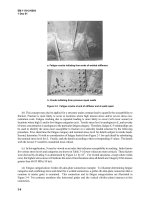
(2) Spare miter gate.
(a) The project had a spare miter gate consisting of five welded modules stacked and bolted together.
The spare gate had been used several times. One month after the last installation, cracks were discovered in
the downstream flanges of three vertical girders. The cracks originated at the downstream face of the flange
in the heat-affected zone at the toe of a transverse fillet weld. (This detail has low fatigue strength.) The
cracks then propagated through the flange and into the web. After cracking, the downstream face of the
flange was 12.5 mm (0.5 in.) out of vertical alignment.
(b) Quick repairs were performed by operations personnel, without input from engineering personnel.
The web crack was filled with weld metal. The flange cracks were gouged and welded, and two small bars
were fillet welded across the crack. The bar material is unknown. These repairs served to get the gate back
into service immediately. However, reliable long-term repairs should be developed and implemented. This
example is further discussed in paragraph 8-6b.
(3) Submersible lift gate.
(a) This project includes a submersible lift gate as the primary upstream lock gate. The gate consists of
two leaves with six horizontal girders spanning 33.5 m (110 ft). Several cracks were discovered in one leaf
while the lock was out of service for other repairs. Subsequent detailed inspection identified over 100 cracks
in girder flanges and bracing members. One crack extended through the downstream flange of a horizontal
girder and 1 m (3 ft) into the 2.5-m- (8-ft-) deep web.
1-3
EM 1110-2-6054
1 Dec 01
(b) This gate was subjected to a detailed investigation to determine the cause of the cracking. The study
identified several contributing factors: the original design had ignored a loading case and had included
improper loading assumptions; limit switches were improperly stopping the gate before it reached its
supports; the design ignored higher stresses caused by eccentric connections on the downstream face; most of
the original welds did not meet current American Welding Society (AWS) quality standards; the steel for the
gate had a low fracture toughness, ranging from 6.8 J (5 ft-lb) at 0
o
C (32
o
F) to 20 J (15 ft-lb) at 21
o
C
(70
o
F).
(c) Repair procedures were designed by engineering personnel for this gate. However, the specified weld
procedures were not used by the contractor, and the welders were not properly qualified per AWS require-
ments. These factors may have caused inadequate repair welds, which duplicates part of the causes of the
original cracking problem. This example is further discussed in paragraph 8-6c.
1-6. Mandatory Requirements
This manual provides guidance for the protection of USACE structures. In certain cases, guidance
requirements are considered mandatory because they are critical to project safety and performance as
discussed in ER 1110-2-1150. Structural inspection and evaluation (and repair if necessary) are critical.
These are best carried out on a case-by-case basis, however, and general mandatory requirements are not
provided. In the inspection, evaluation, and repair process, guidance contained herein should be used where
appropriate.
1-4
EM 1110-2-6054
1 Dec 01
2-1
Chapter 2
Causes of Structural Deterioration
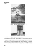
2-1. Corrosion
a. Effects of corrosion. Corrosion can seriously weaken a structure or impair its operation, so the effect
of corrosion on the strength, stability, and serviceability of hydraulic steel structures must be evaluated. The
major degrading effects of corrosion on structural members are a loss of cross section, buildup of corrosion
products at connection details, and a notching effect that creates stress concentrations.
(1) A loss of cross section in a member causes a reduction in strength and stiffness that leads to increased
stress levels and deformation without any change in the imposed loading. Flexure, shear, and buckling strength
may all be affected. Depending on the location of corrosion, the percentage reduction in strength considering
these different modes of failure is not generally not the same.
(2) A buildup of corrosion products can be particularly damaging at connection details. For example,
corrosion buildup in a tainter gate trunnion or lift gate roller guides can lead to extremely high hoist loads. At
connections between adjacent plates or angles, a buildup of rust can cause prying action. This is referred to as
corrosion packout and results from expansion during the corrosion process.
(3) Localized pitting corrosion can form notches that may serve as fracture initiation sites. Notching
significantly reduces the member fatigue life.
b. Common types of corrosion. Corrosion is degradation of a material due to reaction with its environ-
ment. All corrosion processes include electrochemical reactions. Galvanic corrosion, pitting corrosion, crevice
corrosion, and general corrosion are purely electrochemical. Erosion corrosion and stress corrosion, however,
result from the combined action of chemical plus mechanical factors. In general, hydraulic steel structures are
susceptible to three types of corrosion: general atmospheric corrosion, localized corrosion, and mechanically
assisted corrosion (Slater 1987). For any case, the type of corrosion and cause should be identified to assure
that a meaningful evaluation is performed.
(1) General atmospheric corrosion is defined as corrosive attack that results in uniform thinning spread
over a wide area. It is expected to occur in the ambient environment of hydraulic steel structures but is not
likely to cause significant structural degradation.
(2) Localized corrosion is the type of corrosion most likely to affect hydraulic steel structures. Five types
of localized corrosion are possible:
(a) Crevice corrosion occurs in narrow openings between two contact surfaces, such as between adjoining
plates or angles in a connection. It can also occur between a steel component and a nonmetal one (under the
seals, a paint layer, debris, sand or silt, or organisms caught on the gate members). It can lead to blistering and
failure of the paint system, which further promotes corrosion.
(b) Pitting corrosion occurs on bare metal surfaces as well as under paint films. It is characterized by
small cavities penetrating into the surface over a very localized area (at a point). If pitting occurs under paint,
it can result in the formation of a blister and failure of the paint system.
(c) Galvanic corrosion can occur in gate structures where steels with different electrochemical potential
(dissimilar metals) are in contact. The corrosion typically causes blistering or discoloration of the paint and