Inspection Evaluation And Repair Of Steel structures Part 3 potx
Bạn đang xem bản rút gọn của tài liệu. Xem và tải ngay bản đầy đủ của tài liệu tại đây (446.59 KB, 10 trang )
EM 1110-2-6054
1 Dec 01
2-12
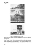
Figure 2-3. Typical fatigue cracking of riveted member
Figure 2-4. Crack surface at the edge of rivet hole
Therefore, fatigue cracks would more likely be detected long before the load-carrying capacity of the riveted
member is exhausted.
d. Fatigue strength of corroded members. For severely corroded members where corrosion notching has
occurred, Category E or E' curves and the corresponding fatigue limits have been suggested for cases. When
corrosion is severe and notching occurs, a fatigue crack may initiate from the corroded region as shown in
Figure 2-5. In cases where corrosion has resulted in loss of more than 20 percent of the cross section, the
corresponding increase in stress should also be considered.
EM 1110-2-6054
1 Dec 01
2-13
Figure 2-5. Fatigue crack from corrosion notch into rivet hole
e. Variable-amplitude fatigue loading.
(1) Most of the fatigue test data and the S
r
-N curves in Figures 2-1 and 2-2 were established from
constant-amplitude cyclic loads. In reality, however, structural members are subjected to variable-amplitude
cyclic loads resulting in a spectrum of various stress ranges. Variable-amplitude fatigue loading may occur on
hydraulic steel structures.
(2) In order to use the available S
r
-N curves for variable-amplitude stress ranges, an equivalent constant-
amplitude stress range S
re
can be determined from a histogram of the stress ranges (Figure 2-6). S
re
is
calculated as the root-mean-cube of the discrete stress ranges S
ri
Figure 2-6. Sample stress range histogram
EM 1110-2-6054
1 Dec 01
2-14
3
3
rii
m
l=i
re
N
S
n
=
S
∑
(2-3)
where
m = number of stress range blocks
n
i
= number of cycles corresponding to S
ri
S
ri
= magnitude of a stress range block
f. Repeated loading for hydraulic steel structures. The general function of hydraulic steel structures is to
dam and control the release of water. Sources of repeated loading include changes in load due to pool
fluctuations, operation of the hydraulic steel structure, flow-induced vibration, and wind and wave action.
(1) Operation.
(a) Spillway gates. During the routine operation of actuating a spillway gate, cyclic loads are applied to
structural members due to the change in hydrostatic pressure on the structure as the gate is raised and then
lowered. Although this load case has the potential to produce large variation of stress in structural compo-
nents, the frequency of occurrence (a very conservative assumption is one cycle per day) is too low to cause
fatigue damage. One lifting/lowering operation per day results in only 18,000 cycles in a 50-year life. This is
well below the number of cycles necessary for consideration of fatigue. Consequently, the possibility that
repeated loads in spillway gates due to operations would cause fatigue damage is unlikely.
(b) Lock gates. Repeated loading for various structural components occurs due to variation in the lock
chamber water level and to opening and closing of gates. The number of load cycles is a function of the
number of lockages that occurs at the lock. The number of load cycles due to gate operation or
filling/emptying the lock chamber per lockage varies between 0.5 and 1.0 depending on barge traffic patterns.
Gates at busy locks can easily endure greater than 100,000 load cycles within a 50-year life. Therefore, fatigue
loading is significant and must be considered in design and evaluation.
(2) Flow-induced vibration. This phenomenon may produce significant cyclic loads on hydraulic steel
structures because of the potential for the occurrence of high-frequency live load stresses above the fatigue
limit. Spillway gates especially can experience some level of flow-induced vibration whenever water is being
discharged, but severe vibration usually occurs only when the gate is open at a certain position. Vibration of
tainter gates is heavily influenced by flow conditions (i.e., gate opening and tailwater elevation) and bottom
seal details. Approximate measurements have indicated that a frequency of vibration of 5-10 Hz is reasonable
(Bower et al. 1992). This frequency is large enough to cause fatigue damage in a short time even for relatively
low stress range values. Although a hydraulic steel structure would rarely be operated in such a position for
any length of time, flow-induced vibration should be considered as a possible source of fatigue loading. An
example of the fatigue evaluation of a spillway gate including vibration loading is given in Chapter 7.
(3) Wind and wave action. This is a continuous phenomenon that has not caused fatigue problems in
hydraulic steel structures probably due to the low magnitude of stress range for normal conditions.
2-4. Design Deficiencies
Many existing hydraulic steel structures were designed during the early and mid-1900's. Analysis and design
technologies have significantly improved, producing the current design methodology. Original design loading
conditions may no longer be valid for the operation of the existing structure, and overstress conditions may
EM 1110-2-6054
1 Dec 01
2-15
exist. Current information, including modern welding practice and fatigue and fracture control in structures,
was not available when many of the initial designs were performed. Consequently, low category fatigue details
and low toughness materials exist on some hydraulic steel structures. In addition, the amount of corrosion
anticipated in the original design may not accurately reflect actual conditions, and structural members may now
be undersized. To evaluate existing structures properly, it is important that the analysis and design information
for the structure be reviewed to assure no design deficiencies exist.
2-5.
Fabrication Discontinuities
a. For strength and economic reasons, EM 1110-2-2703 recommends that hydraulic steel structures be
fabricated using structural-grade carbon steel. Standards such as ASTM A6/A6M or ASTM A898/A898M
have been developed to establish allowable size and number of discontinuities for base metal used to fabricate
hydraulic steel structures. In addition, EM 1110-2-2703 also recommends that the steel structures be welded in
accordance with the Structural Welding Code-Steel (ANSI/AWS D1.1). This code provides a standard for
limiting the size and number of various types of discontinuities that develop during welding. Although these
criteria exist, when a hydraulic steel structure goes into service, it does contain discontinuities.
b. Discontinuities that exist during initial fabrication are rejectable only when they exceed specified
requirements in terms of type, size, distribution, or location as specified by ANSI/AWS D1.1. Welded
fabrication can contain various types of discontinuities that may be detrimental (see paragraph 2-2). This is
especially important when considering weldments involving thick plates, because thick plates are inherently
less tough and welding residual stresses are high.
c. Frequently, plates 38 mm (1-1/2 in.) in thickness and greater are used as primary welded structural
components on hydraulic steel structures. It is not uncommon to see such thick plates used as flanges,
embedded anchorage used to support hydraulic steel structures, hinge and operating equipment connections,
diagonal bracing, lifting or jacking assemblies, or platforms to support operating equipment that actuates the
hydraulic steel structures. In addition, thick castings such as sector gears used for operating such structures as
lock gates may be susceptible to brittle fracture. Hydraulic steel structures have experienced cracking during
fabrication and after the thick assemblies are welded and placed into service.
2-6. Operation and Maintenance
Proper operation and maintenance of hydraulic steel structures are necessary to prevent structural deterioration.
The following items are possible causes of structural deterioration that should be considered:
a. Weld repairs are often sources of future cracking or fracture problems, particularly if the existing steel
had poor weldability as is often the case with older gates.
b. If moving connections are not lubricated properly, the bushings will wear and result in misalignment of
the gate. The misalignment will subsequently wear contact blocks and seals, and unforeseen loads may
develop.
c. Malfunctioning limit switches could result in detrimental loads and wear.
d. A coating system or cathodic protection that is not maintained can result in detrimental corrosion.
e. Loss of prestress in the gate leaf diagonals reduces the torsional stability of miter gates during opening
and closing.
EM 1110-2-6054
1 Dec 01
2-16
f. Proper maintenance of timber fenders and bumpers is necessary to provide protection to the gate and
minimize deterioration.
2-7. Unforeseen Loading
a. Accidental overload or dynamic loading of a gate can result in deformed members or fracture. When
structural members become plastically deformed or buckled, they may have significantly reduced strength and/
or otherwise impair the performance of a hydraulic steel structure. The extent and nature of any noticeable
plastic deformation should be noted and accurately described during the inspection process, and its effect on
the performance of the structure should be assessed in the ensuing evaluation as further discussed in Chapter 6.
Fractures that occur must generally be repaired. Considerations for repair are discussed in Chapter 8.
b. Dynamic loading due to hydraulic flow and impact loading due to vessel collision are currently unpre-
dictable. The dynamic loading may be caused by hydraulic flow at the seals or may occur when lock gates are
used to supplement chamber filling or skim ice and debris. Impact loading can occur from malfunctioning
equipment on moving vessels or operator error. Fracture likelihood is enhanced with dynamic loads, since the
fracture toughness for steels decreases with increasing load rate. Other unusual loadings may occur from
malfunctioning limit switches or debris trapped at interfaces between moving parts. It is also possible that
unusual loads may develop on hydraulic steel structures supported by walls that are settling or moving. These
unusual loads can cause overstressing and lead to deterioration.
EM 1110-2-6054
1 Dec 01
3-1
Chapter 3
Periodic Inspection
3-1. Purpose of Inspection
a. As discussed in Chapter 2, existing hydraulic steel structures are subjected to conditions that could
cause structural deterioration and premature failure. Periodic inspection shall be conducted in accordance with
ER 1110-2-100 and ER 1110-2-8157. Periodic inspections on hydraulic steel structures are primarily visual
inspections. The inspection procedure should be designed to detect damage, deterioration, or signs of distress
to avert any premature failure of the structure and to identify any future maintenance or repair requirements.
The periodic inspection should assure that all critical members and connections are fit for service until the next
scheduled inspection. Critical members and connections are those structural elements whose failure would
render the hydraulic steel structure inoperable. Fitness for service means that the material and fabrication
quality are at an appropriate level considering risks and consequences of failure. To be effective, the periodic
inspection should be a systematic and complete examination of the entire structure with particular attention
given to the critical locations. It should be done while the structure is in use and, to the extent possible, lifted
out of the water. Ideally, inspections should be planned to coincide with scheduled dewatering of the structure.
b. If the periodic inspection indicates that a structure may be distressed, a more detailed inspection and
evaluation may be necessary. This detailed inspection may require nondestructive and/or destructive testing as
discussed in Chapters 4 and 5. The information obtained from the inspections and tests will then be used to
perform a structural evaluation as discussed in Chapter 6 and make a recommendation for future action. This
chapter will further discuss the visual inspection that should be performed during the periodic inspection.
3-2. Inspection Procedures
The following four primary steps are considered necessary to perform a periodic inspection adequately:
preinspection assessment, inspection, evaluation, and recommendations.
a. Preinspection assessment.
(1) To conduct a detailed inspection over the entire hydraulic steel structure on a project is not
economical, if at all possible. Prior to inspection, critical areas should be identified to determine which areas
of the structure require the most attention (paragraph 3-3). The inspector should prepare by reviewing the
design and drawings, previous inspection reports, and all operations/maintenance records since the most recent
inspection.
(2) The inspector should review structural drawings to become familiar with the components and
operation of each hydraulic steel structure. Locations and details on the structure prone to fracture or fatigue
cracking or susceptible to corrosion should be identified. These locations should receive more attention during
the inspection. The procedure for identifying critical areas and a checklist of locations (both specific and
general) that are susceptible to fracture and corrosion are presented in paragraphs 3-3 and 3-5, respectively, to
assist the inspector during the preinspection.
(3) Review of previous inspection reports and operations records will aid in defining occurrence of
unusual circumstances or a history of problems. Distress may occur due operational problems (paragraph 2-6)
or the occurrence of unusual loads (paragraph 2-7). These events could have imposed high-magnitude stresses
and/or a large number of stress cycles, which may cause cracks to develop or members to buckle.
EM 1110-2-6054
1 Dec 01
3-2
b. Inspection.
(1) Inspection is the activity of examining a structure to ascertain quality, detect damage or deterioration,
or otherwise appraise a structure. Particular attention should be given to gate operation (and cathodic
protection, if applicable) and the critical locations cited in the preinspection assessment. For the main
structural elements, items to consider during inspection include occurrence of cracking or excessive
deformation, excessive corrosion, loose rivets, fabrication defects, and damage due to impact from debris.
Additionally, all previously reported conditions should be thoroughly inspected. Detailed procedures for
inspecting hydraulic steel structures for occurrence of these items are presented in Chapter 4.
(2) Mechanical and electrical components such as seals, lifting mechanisms, bearings, limit switches,
cathodic protection systems, and heaters are critical to the operation of hydraulic steel structures and should be
inspected appropriately. These components should be checked for general working condition, corrosion,
trapped debris, necessary tolerances, and proper lubrication. The structure should also be visually inspected for
weld condition and surface defects.
(3) All observations of damage or unusual conditions should be documented in sufficient detail so that all
necessary information for a structural evaluation is included and the severity of the condition can be
quantitatively compared with previous and future observations.
c. Evaluation. Evaluation of the effects of existing cracks, excessive corrosion, excessive deformation,
mechanical problems, weld bead noncompliance with the ANSI/AWS D1.1 standards, and the occurrence of
unusual loads must be conducted. This requires qualitative as well as quantitative analysis of inspection data
and unusual events reported in previous assessments and evaluations, considering loading and performance
criteria required for the existing structure. The periodic inspection is the initial evaluation in the process of
determining the structural adequacy of a structure. If surface cracks or fractured members are discovered
during the periodic inspections, detailed inspection and evaluation shall be performed for the entire gate. The
strength and stability of corroded members should be calculated. Information on evaluation and
recommendation procedures is provided in Chapter 6.
d. Recommendations. This task is defined as the process of determining requirements pertaining to fre-
quency of future inspection or remediation of problems, if required. Chapter 6 provides some general
information on appropriate recommendations.
3-3. Critical Members and Connections
Critical structural members and connections can be determined from structural analysis of the hydraulic steel
structure. This should include local stress concentrations and fatigue considerations. In addition, effects from
existing corrosion and reduced weld quality or associated residual stresses should be considered. This analysis
will require information pertaining to the existing mechanical properties of the structural material and weld
(i.e., strength, toughness, ductility) and the location, type, size, and orientation of any known discontinuities.
a. Critical areas for fracture. Areas in a hydraulic steel structure that may be susceptible to fracture may
be determined by considering the combined effect of nominal tensile stress levels and complexity of
connection details. Connection details interrupt or change the flow of stress, resulting in stress concentrations;
therefore, a moderate level of nominal tension stress occurring at a complex detail (stress concentration) may
be amplified to a significant level. To identify critical areas for fracture, determine locations of moderate to
high nominal tensile stress levels throughout the structure, identify locations or details where there are signifi-
cant stress concentrations, and combine the effects of stress level and sensitive details.
EM 1110-2-6054
1 Dec 01
3-3
(1) Determination of stress levels.
(a) In determining the critical locations for fracture, only nominal tensile stresses are considered since
fracture will not occur under constant compressive stress. In contrast, fatigue cracking may occur under cyclic
compressive loading when tensile residual stress is present. For example, if a residual tensile stress of
172.4 MPa (25 ksi) exists, a calculated stress variation from zero to 68.95 MPa (10 ksi) in compression would
actually be a variation from 172.4 MPa (25 ksi) to 103.4 MPa (15 ksi), which could cause fatigue cracking.
Welded members may include high tensile residual stress (near the yield stress in most cases) in the welded
region. (EM 1110-2-2105 requires that fatigue design be considered for welded members subject to any
computed stress variation, whether it is tension or compression.)
(b) Stress levels in hydraulic steel structures can be determined from a variety of different analytical
methods ranging from idealized two-dimensional (2-D) analysis to detailed three-dimensional (3-D) finite
element analysis. In most cases, a simple 2-D analysis, such as that used in design, should be sufficient. A
more detailed analysis may be required to determine the stress levels in a hydraulic steel structure if the gate
has some history of unusual loading (unsymmetric loading or overload). The type of analysis to be performed
is dependent on the particular stresses in question and the loading condition. In general, there will be common
high-stress areas for a given type of hydraulic steel structure. For example, the following are typical locations
of high-tension stress areas common to such hydraulic steel structures as roller, tainter, and lift gates:
• Roller gates are essentially simply supported and have high tensile stresses at midlength. High stress
also occurs at the ends due to large shear forces, unintended flexural restraint, and lifting loads. Addi-
tionally, high tension stresses may exist at the junction between the apron assembly and the main tube.
• Tainter gates generally have significant tensile stresses in the downstream flanges at the midlength of
the horizontal girders (lower girders are more critical), in the upstream flange of girders, in the outside
flange of end frame struts near the girder-strut connections, and where the end frames join the trunnion
assemblies (tensile stresses may occur in the end frame due to trunnion pin friction). High tensile
stresses will also occur in the upstream flange of skin plate ribs at the horizontal girders.
• Lift gates resist horizontal (due to hydrostatic pressure) and vertical (due to hydrostatic pressure and
structural weight) loads. Under horizontal loading, lift gates act essentially as simply supported
stiffened plate structures, and significant tensile stresses are likely to occur in the downstream flange at
the midlength of the horizontal girders, with highest stresses occurring in the lower girders. High
tension stresses may also develop in the upstream flange near the ends of the girders if rotational
restraint is imposed due to binding of the guide wheels (from debris or ice collecting at the slot in the
pier). Because of displacement under vertical loading, significant tensile stresses may also develop in
the bottom of downstream girder flanges and in various connections as discussed in c below.
(2) Detail categorization. The purpose of this task is to identify the severity of the stress concentration for
various details. Since all details contain some level of stress concentration, a means of determining the relative
stress concentration effect of the different connections is needed. For connections made up of welded details,
this may be accomplished by determining the appropriate fatigue categories that reflect the severity of the stress
concentration introduced by the particular detail.
(a) A complex welded connection will likely consist of several weld details, each with a corresponding
fatigue category. For example, consider a gusset plate connection that joins bracing members to the
downstream flange of a built-up girder (Figure 3-1). Evaluation of girder flexure includes the longitudinal
web-to-flange weld, the attachment of the welded stiffener to the girder, and the attachment of the gusset plate
to the girder flange. The fatigue category of the connection is determined by the most critical category detail in
the connection. The fatigue category for a particular welded detail is based on the type of weld, geometry
EM 1110-2-6054
1 Dec 01
3-4
Figure 3-1. Bracing-girder connection
of the detail, and the direction of the applied stress. The general procedure for determining the fatigue category
of a welded connection is summarized in the following list. Examples that illustrate this process are provided
in (4) and (5) below.
• Locate the main member being examined and define the structural action. At the intersection of two
primary members, the structural action of each member must be considered independently and the weld
GUSSET
PLATE
EM 1110-2-6054
1 Dec 01
3-5
details categorized accordingly. A particular detail may have different fatigue category classifications
when the structural action of the different members is considered.
• For each detail, determine the most appropriate example, general condition, and situation (geometry,
weld type, loading direction, etc.) as described in Table 2-1.
• Select the appropriate fatigue category as specified in Table 2-1 for each detail.
• For the member and structural action considered, determine the fatigue category for the connection
based on the most critical weld detail.
(b) All riveted details, regardless of particular configuration, may be classified as a Category C or D.
Welded attachments, tack welds, seal welds, or repair welds that exist in riveted structures, however, may
lower the fatigue category of a riveted detail from C or D to Category E or E'. Figure 3-2 shows a fatigue crack
starting from a tack weld on a riveted bridge member. The crack initiated at the toe of the tack weld and grew
into the riveted plate in the direction perpendicular to the primary tensile stress. Similar damage could occur
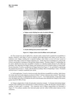
on any riveted member. Figure 3-3(a) shows fatigue cracks initiating from the ends of welded stiffeners in the
end shield of a riveted roller gate. Figure 3-3(b) shows cracks initiating from previous repair welds. In this
instance, attempts to strengthen a riveted gate by adding welded stiffening plates created a detail susceptible to
fatigue (high stress concentration).
Figure 3-2. Fatigue crack at tack weld on a riveted member
(3) Identifying critical areas: Combining stress and detail.
(a) In determining the most critical areas susceptible to cracking, the combined effect of stress levels and
stress concentration must be considered. For a structural component or detail subjected to fatigue loading, the
combined effect of the stress range S
r
and the stress concentration is reflected in the AASHTO S
r
-N curves of
Figure 2-1. The fatigue life N is a function of S
r
and type of detail (fatigue category); N is lower for higher S
r
and more severe stress concentration (lower fatigue category). In a comparison of two or more details, the one
with the lowest fatigue life would be the most critical.


