Machine Design Databook Episode 2 part 7 pdf
Bạn đang xem bản rút gọn của tài liệu. Xem và tải ngay bản đầy đủ của tài liệu tại đây (533.97 KB, 40 trang )
The general expression for size factor
Wire diameter
SELECTION OF MATERIALS AND
STRESSES FOR SPRINGS
For materials for springs
7
The torsional yield strength
The maximum allowable torsional stress for static
applications according to Joerres
8;9;11
The maximum allowable torsional stress according to
Shigley and Mischke
9
The shear endurance limit according to Zimmerli
10
The torsional modulus of rupture
e
sz
¼ 0:86 þ
0:07
d
USCS ð20-45cÞ
for steel, where d in in
e
sz
¼ 0:986 þ
0:0043
d
USCS ð20-45dÞ
for monel metal, where d in in
e
sz
¼ 0:86 þ
1:8
d
SI ð20-45eÞ
for steel, where d in mm
e
sz
¼ 0:986 þ
0:1
d
SI ð20-45fÞ
for monel metal, where d in mm
k
sz
¼ 4:66h
0:35
where h in m SI ð20-46aÞ
k
sz
¼ 1:27h
0:35
where h in in USCS ð20-46bÞ
k
sz
¼ 0:415h
0:35
where h in mm SI ð20-46cÞ
d ¼
3
ffiffiffiffiffiffiffiffiffiffiffiffiffi
8kFD
d
e
sz
s
ð20-47Þ
Refer to Tables 20-8 and 20-10 and Figs. 20-7b and
20-7c.
0:35
sut
sy
0:52
sut
for steels ð20-47aÞ
sy
¼
a
¼
0:45
sut
cold-drawn carbon steel
0:50
sut
hardened and tempered
carbon and low-alloy steel
0:35
sut
austenitic stainless steel
and nonferrous alloys
8
>
>
>
>
>
<
>
>
>
>
>
:
ð20-47bÞ
where
sy
¼ torsional yield strength, MPa (psi)
sy
¼
a
¼ 0:56
sut
ð20-47cÞ
sf
¼ 310 MPa ð45 kpsiÞð20-47dÞ
for unpeened springs
sf
¼ 465 MPa ð67:5 kpsiÞð20-47eÞ
for peened springs
su
¼ 0:67
sut
ð20-47f Þ
Particular Formula
20.14 CHAPTER TWENTY
Downloaded from Digital Engineering Library @ McGraw-Hill (www.digitalengineeringlibrary.com)
Copyright © 2004 The McGraw-Hill Companies. All rights reserved.
Any use is subject to the Terms of Use as given at the website.
SPRINGS
The weight of the active coil of a helical spring
For free-length tolerances, coil diameter tolerances,
and load tolerances of helical compression springs
DESIGN OF HELICAL COMPRESSION SPRINGS
Design stress
The size factor
The design stress
W ¼
2
d
2
Di
4
ð20-47gÞ
where ¼ weight of coil of helical spring per unit
volume
Refer to Tables 20-11 to 20-13.
k
sz
¼
d
0:35
0:355
where d in m SI ð20-48aÞ
k
sz
¼
d
0:25
0:84
where d in in USCS ð20-48bÞ
k
sz
¼
d
0:25
1:89
where d in mm SI ð20-48cÞ
ds
¼
e
n
a
k
sz
¼
0:335
e
n
a
d
0:25
SI ð20-49aÞ
where
e
in MPa and d in m
ds
¼
e
n
a
k
sz
¼
0:84
e
n
a
d
0:25
USCS ð20-49bÞ
where
e
in psi and d in in
TABLE 20-8
Spring design stress,
d
, MPa (kpsi)
Severe service Average service Light
Wire diameter, mm MPa kpsi MPa kpsi MPa kpsi
2.15 413.8 60 517.3 75 641.4 93
2.15–4.70 379.0 55 476.6 69 585.4 85
4.70–8.10 331.0 48 413.8 60 510.0 74
8.10–13.45 289.3 42 358.4 52 448.2 65
13.45–24.65 248.1 36 310.4 45 385.9 56
24.65–38.10 220.6 32 275.6 40 344.7 50
TABLE 20-9
Factors for helical springs with wires of rectangular cross section
Ratio b=h ¼ m 11.21.52.02.535101
Factor k 0.416 0.438 0.462 0.492 0.516 0.534 0.582 0.624 0.666
Factor k
2
0.180 0.212 0.250 0.292 0.317 0.335 0.371 0.398 0.424
Particular Formula
SPRINGS
20.15
Downloaded from Digital Engineering Library @ McGraw-Hill (www.digitalengineeringlibrary.com)
Copyright © 2004 The McGraw-Hill Companies. All rights reserved.
Any use is subject to the Terms of Use as given at the website.
SPRINGS
TABLE 20-10
Chemical composition and mechanical properties of spring materials
Tensile properties Torsional properties of wire
Analysis Ultimate strength Elastic limit Modulus of elasticity, E Ultimate strength Elastic limit Modulus in torsion, G
Material Element % Mpa kpsi GPa kpsi GPa Mpsi Rockwell hardness MPa kpsi GPa kpsi GPa Mpsi Chief uses
Flat Cold-rolled Spring Steel
Watch spring steel C 1.10–1.19 2274–2412 330–350 2.14–2.28 310–330 220 32 C55–55 Not used Not used Not used Main springs for watches
Mn 0.15–0.25 and similar uses
Clock spring steel Clock and motor springs,
AS 100 C 0.90–1.05 1240–2343 180–340 1.03–2.14 150–310 207 30 C40–52 Not used Not used Not used miscellaneous flat springs
SAE 1095 Mn 0.20–0.50 for high stress
Flat spring steel
AS 101 C 0.65–0.80 1103–2206 160–320 0.86–1.93 125–280 207 30 Annealed, B70–85 Not used Not used Not used Miscellaneous flat springs
SAE 1074 Mn 0.50–0.90 tempered C38–50
Carbon Steel Wires
High–carbon wire C 0.85–0.95 1382–1725 200–250 1.10–1.45 160–210 207 30 C44–48 1103 160–200 0.76 110–150 79 11.5 High-grade helical springs
AS 8 Mn 0.25–0.60 1377 1.03 or wire forms
Oil-tempered wire
(ASTM A229–41) C 0.60–0.70 1068–2059 155–300 0.83–1.73 120–250 794 115–200 0.55 80–130 General spring use
AS10 Mn 0.60–0.90 200 29 C42–46 1377 0.90 79 11. 5
Music wire (ASTM
A228–47) C 0.70–1.00 1725–3790 250–500 1.03–2.41 1 50–350 1034 150–300 0.62 90–180 79 11.5 Miscellaneous small
AS 5 Mn 0.30–0.60 207 30 2069 1.24 82 12.0 springs of various types—
depending high quality
on size
Hard-drawn spring
wire
(ASTM A227–47) C 0.60–0.70
1034–2068
150–300 0.69–1.38 100–200 828 120–220 0.51 75–130 Same uses as music wire
AS 20 Mn 0.90–1.20 200 29 1515 0.90 79 11.5 but lower-quality wire
Hot-rolled Special Steel
Hot-rolled bars
SAE 1095, C 0.90–1.05 1206–1377 175–200 0.73–0.97 105–140 760 110–140 0.51 75 Hot-rolled heavy coil or
ASTM A14–42 Mn 0.25–0.50 196 28.5 C40–46 965 0.76 110 72 10.5 flat springs
Alloy and Stainless Spring Materials
Chrome-vanadium C 0.45–0.55 1377 200–250 1.24 180–230 965 0.69 100–130
alloy steel Mn 0.50–0.80 207 30 C42–48 140–175 79 11.5 Cold–rolled or drawn:
(SAE 6150) Cr 0.80–1.10 1725 1.58 1206 0.90 special applications
AS 32 V 0.15–0.18
Silico-manganese C 0.55–0.65
alloy steel Mn 0.60–0.90 Used as a lower–cost
(SAE 9260) Si 1.80–2.20
About the same as chrome vanadium About the same as chrome vanadium
material in place of
Type 18–8 stainless C 17–20 1103 160–330 0.41 60–260 chrome vanadium
(Type 302, Ni 7–10 193 28 C35–45 828 120–240 0.31 45–140
SAE 30915) C 0.08–0.15 2275 1.79 69 10 Best corrosion resistance,
Mn 2 max 1653 0.97 fair temperature
Si 0.30–0.75 resistance
20.16
Downloaded from Digital Engineering Library @ McGraw-Hill (www.digitalengineeringlibrary.com)
Copyright © 2004 The McGraw-Hill Companies. All rights reserved.
Any use is subject to the Terms of Use as given at the website.
SPRINGS
Cutlery-type
stainless Cr 12–14 1171 170–250 0.90 130–200 828 120–180 0.55 80–120 76 Resists corrosion when
(Type 420) C 0.25–0.40 1725 1.38 193 28 C42–47 1240 0.83 11 polished; good
temperature resistance
Nonferrous Spring Materials
Spring brass For electrical
AS 55 Cu 64–74 691 100–130 0.27 308 45–90 0.21 30–60 conductivity at low
AS 155 Zn balance 897 0.41 107 15 B90 622 0.41 38 5.5 stresses; for corrosion
resistance
Nickel silver Cu 56 897 130–150 0.55 80–110 588 85–100 0.41 60–70 Used for its color;
Zn 25 1034 0.76 110 16 B95–100 691 0.48 38 5.5 corrosion resistance
Ni 18
Phosphor bronze Cu 91–93 691 100–150 0.41 60–110
AS 60 Sn 7–9 554 0.35 Used for corrosion
AS 160 or 103 15 B90–100 80–105 50–85 43 6.25 resistance and electrical
Cu 94–96 102 0.76 725 0.59 conductivity
Sn 4–6
Nonferrous Spring Materials
Silicon bronze (made Si 2–3
under various trade Sn or Small Used as substitute for
names) Mn amounts
Properties similar to those of phosphor bronze Properties similar to those of phosphor bronze
phosphor bronze
AS 46 Cu balance
AS 146
Monel Ni 64 691 100–140 0.55 80–120 519 75–110 0.31 45–70 Resists corrosion;
AS 40 Cu 26 964 0.83 179 26 C23–28 760 0.48 65 9.5 moderate stresses to
AS 140 Mn 2.5 204.58C
Fe 2.25
Inconel Ni 80 965 140–175 0.76 110–135 651 95–120 0.38 55–80 Resists corrosion; high
AS 40 Cr 14 1206 0.93 213 31 C30–40 828 0.55 76 11 stresses to 3438C
AS140 Fe Balance
K–Monel Ni 66 1103 160–180 0.79 115–145 725 105–125 0.45 65–85 Resists corrosion; high
AS 40 Cr 29 1241 1.00 179 26 C33–40 862 0.58 65 9.5 stresses to 2328C
AS 140 Al 2.75
Fe 0.90
Z–nickel Ni 98 1241 0.90 828 0.41
Cu 180–230 130–170 207 30 C36–46 120–150 60–90 76 11 Resists corrosion; high
Mn Small 1583 1.17 1034 0.68 stresses to 2888C
Fe amounts
Si
Beryllium-coppcr Cu 98 1103 160–200 0.69 100–150 110 16–18.5 691 100–130 0.45 65–95 41 6–7 Corrosion resistance like
AS 45 Be 2 1377 1.03 127 Subject to C35–42 897 0.66 48 copper; high physical
AS 145 heat Subject to properties for electrical
treatment heat work; low hysteresis
treatment
Note: The property values given in this table do not specify the minimum properties.
Source: Handbook of Mechanical Spring Design, courtesy Associated Spring, Barnes Group Inc., Bristol, Connecticut.
20.17
Downloaded from Digital Engineering Library @ McGraw-Hill (www.digitalengineeringlibrary.com)
Copyright © 2004 The McGraw-Hill Companies. All rights reserved.
Any use is subject to the Terms of Use as given at the website.
SPRINGS
TABLE 20-11
Free-length tolerances of squared and ground helical compression springs
a
Tolerances: Æmm/mm (in/in) of free length
Spring index (D=d)
Number of active
coilspermm(in)46810121416
0.02 (0.5) 0.010 0.011 0.012 0.013 0.015 0.016 0.016
0.04 (1) 0.011 0.013 0.015 0.016 0.017 0.018 0.019
0.08 (2) 0.013 0.015 0.017 0.019 0.020 0.022 0.023
0.2 (4) 0.016 0.018 0.021 0.023 0.024 0.026 0.027
0.3 (8) 0.019 0.022 0.024 0.026 0.028 0.030 0.032
0.5 (12) 0.021 0.024 0.027 0.030 0.032 0.034 0.036
0.6 (16) 0.022 0.026 0.029 0.032 0.034 0.036 0.038
0.8 (20) 0.023 0.027 0.031 0.034 0.036 0.038 0.040
a
For springs less than 12.7 mm (0.500 in) long, use the tolera nces for 12.7 mm (0.500 in). For closed ends not ground, multiply above values by 1.7.
Source: Associated Spring, Barnes Group Inc., Bristol, Connecticut.
TABLE 20-12
Coil diameter tolerances of helical compression and extension springs
Tolerances: Æmm (in)
Spring index ðD=dÞ
Wire diameter,
mm (in) 4 6 8 10 12 14 16
0.38 0.05 0.05 0.08 0.10 0.13 0.15 0.18
(0.015) (0.002) (0.002) (0.003) (0.004) (0.005) (0.006) (0.007)
0.58 0.05 0.08 0.10 0.15 0.18 0.20 0.25
(0.023) (0.002) (0.003) (0.004) (0.006) (0.007) (0.008) (0.010)
0.89 0.05 0.10 0.15 0.18 0.23 0.28 0.33
(0.035) (0.002) (0.004) (0.006) (0.007) (0.009) (0.011) (0.013)
1.30 0.08 0.13 0.18 0.25 0.30 0.38 0.43
(0.051) (0.003) (0.005) (0.007) (0.010) (0.012) (0.015) (0.017)
1.93 0.10 0.18 0.25 0.33 0.41 0.48 0.53
(0.076) (0.004) (0.007) (0.010) (0.013) (0.016) (0.019) (0.021)
2.90 0.15 0.23 0.33 0.46 0.53 0.64 0.74
(0.114) (0.006) (0.009) (0.013) (0.018) (0.021) (0.025) (0.029)
4.34 0.20 0.30 0.43 0.58 0.71 0.84 0.97
(0.171) (0.008) (0.012) (0.017) (0.023) (0.028) (0.033) (0.038)
6.35 0.28 0.38 0.53 0.71 0.90 1.07 1.24
(0.250) (0.011) (0.015) (0.021) (0.028) (0.035) (0.042) (0.049)
9.53 0.41 0.51 0.66 0.94 1.17 1.37 1.63
(0.375) (0.016) (0.020) (0.026) (0.037) (0.046) (0.054) (0.064)
12.70 0.53 0.76 1.02 1.57 2.03 2.54 3.18
(0.500) (0.021) (0.030) (0.040) (0.062) (0.080) (0.100) (0.125)
Source: Associated Spring, Barnes Group Inc., Bristol, Connecticut.
20.18 CHAPTER TWENTY
Downloaded from Digital Engineering Library @ McGraw-Hill (www.digitalengineeringlibrary.com)
Copyright © 2004 The McGraw-Hill Companies. All rights reserved.
Any use is subject to the Terms of Use as given at the website.
SPRINGS
TABLE 20-13
Load tolerances of helical compression springs
Tolerance: Æ% of load, start with tolerance from Table 20-11 multiplied by L
F
Deflection from free length to load, mm (in)
Length
tolerance Æ 1.27 2.54 3.81 5.08 6.35 7.62 10.2 12.7 19.1 25.4 38.1 50.8 76.2 102 152
mm (in) (0.050) (0.100) (0.150) (0.200) (0.250) (0.300) (0.400) (0.500) (0.750) (1.00) (1.50) (2.00) (3.00) (4.00) (6.00)
0.13 (0.005) 12 7 6 5 — — — — — — —————
0.25 (0.010) — 12 8.5 7 6.5 5.5 5 — — — —————
0.51 (0.020) — 22 15.5 12 10 8.5 7 6 5 — —————
0.76 (0.030) — — 22 17 14 12 9.5 8 6 5 —————
1.0 (0.040) — — — 22 18 15.5 12 10 7.5 6 5 ————
1.3 (0.050) — — — — 22 19 14.5 12 9 7 5.5 ————
1.5 (0.060) — — — — 25 22 17 14 10 8 6 5 — — —
1.8 (0.070) — — — — — 25 19.5 16 11 9 6.5 5.5 — — —
2.0 (0.080) — — — — — — 22 18 12.5 10 7.5 6 5 — —
2.3 (0.090) — — — — — — 25 20 14 11 8 6 5 — —
2.5 (0.100) — — — — — — — 22 15.5 12 8.5 7 5.5 — —
5.1 (0.200) — — — — — — — — — 22 15.5 12 8.5 7 5.5
7.6 (0.300) — — — — — — — — — — 22 17 12 9.5 7
10.2 (0.400) — — — — — — — — — — — 21 15 12 8.5
12.7 (0.500) — — — — — — — — — — — 25 18.5 14.5 10.5
First load test at not less than 15% of available deflection; final load test at not more than 85% of available deflection.
Source: Associated Spring, Barnes Group Inc., Bristol, Connecticut.
TABLE 20-14
Equations for springs with different types of ends
2,3
Particular
Active coils, ii
0
i
0
À
1
2
i
0
À 2 i
0
À 2
Total coils, i
0
l
o
À d
p
l
o
p
l
o
À 3d
p
l
o
À 2d
p
þ 2
Free length, l
o
or l
f
ip þ dip ipþ 3dipþ 2d
Pitch, p
l
o
À d
i
0
l
o
i
0
l
o
À 3d
i
0
l
o
À 2d
i
0
Solid height, hdði
0
þ 1Þ dði
0
þ
1
2
Þ dði
0
þ 1Þ i
0
d
Source: K. Lingaiah and B. R. Narayana Iyengar, Machine Design Data Handbook, Vol. I, Suma Publishers, Bangalore, India, 1986, and K.
Lingaiah, Machine Design Data Handbook, Vol. 11, Suma Publishers, Bangalore, India, 1986.
SPRINGS 20.19
Downloaded from Digital Engineering Library @ McGraw-Hill (www.digitalengineeringlibrary.com)
Copyright © 2004 The McGraw-Hill Companies. All rights reserved.
Any use is subject to the Terms of Use as given at the website.
SPRINGS
The actual factor of safety or reliability factor
The wire diameter for static loading
The wire diameter where there is no space limitation
ðD ¼ cdÞ
ds
¼
e
n
a
k
sz
¼
1:89
e
n
a
d
0:25
Metric ð20-49cÞ
where
e
in kgf/mm
2
and d in mm
where n
a
¼ actual factor of safety or reliability
factor
n
a
¼
FðcompressedÞ
FðworkingÞ
ð20-50aÞ
n
a
¼
free length À fully compressed length
free length À working length
¼
y þa
y
ð20-50bÞ
where y is deflection under working load, m (mm),
a is the clearance which is to be added when
determining the free length of the spring and
is made equal to 25% of the working
deflection
Generally n
a
is chosen at 1.25.
d ¼ 1:445
6n
a
F
e
0:4
D
0:3
¼ 2:945
n
a
F
e
0:4
D
0:3
SI ð20-51aÞ
where F in N,
e
in MPa, D in m, and d in m
d ¼ 0:724
6n
a
F
e
0:4
D
0:3
¼ 1:48
n
a
F
e
0:4
D
0:3
Metric ð20-51bÞ
where F in kgf,
e
in kgf/mm
2
, D in mm, and d in
mm
d ¼
6n
a
F
e
0:4
D
0:3
¼ 2:05
n
a
F
e
0:4
D
0:3
USCS ð20-51cÞ
where F in lbf,
e
in psi, D in in, and d in in
d ¼ 4:64
n
a
F
e
0:57
c
0:43
SI ð20-51dÞ
where d in m, F in N,
e
in Pa
d ¼
6n
a
F
e
0:57
c
0:43
USCS ð20-51eÞ
where d in in, F in lbf,
e
in psi
TABLE 20-15
Curvature factor k
c
c 34678910
k
c
1.35 1.25 1.15 1.13 1.11 1.1 1.09
Particular Formula
20.20 CHAPTER TWENTY
Downloaded from Digital Engineering Library @ McGraw-Hill (www.digitalengineeringlibrary.com)
Copyright © 2004 The McGraw-Hill Companies. All rights reserved.
Any use is subject to the Terms of Use as given at the website.
SPRINGS
Final dimensions (Fig. 20-7d)
The number of active coils
The minimum free length of the spring
Outside diameter of cod of helical spring
Solid length (or height) of helical spring
Pitch of spring
Free length of helical spring l
f
or l
o
Maximum working length of helical spring
Minimum working length of helical spring
Springs with different types of ends
1;2;3
STABILITY OF HELICAL SPRINGS
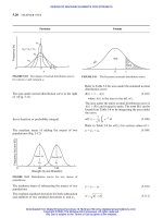
The critical axial load that can cause buckling
d ¼ 1:77
n
a
F
e
0:57
c
0:43
Metric ð20-51fÞ
where d in mm, F in kgf,
e
in kgf/mm
2
i ¼
yd
4
G
8FD
3
¼
ydG
8Fc
3
¼
kydG
D
2
ð20-52Þ
l
f
!ði þ nÞd þy þ a ð20-53Þ
where
a ¼ clearance, m (mm)
n ¼ 2 if ends are bent before grinding
¼ 1 if ends are either ground or bent
¼ 0 if ends are neither ground nor bent
D
o
¼ D þ d ð20-53aÞ
l
s
¼ i
t
d ð20-53bÞ
p ¼
y
s
i
þ d ð20-53cÞ
l
f
À l
s
þ y
s
ð20-53dÞ
l
max
¼ l
f
À y
max
ð20-53eÞ
l
min
¼ l
f
À y
min
ð20-53fÞ
where i
t
¼ total number of coild in the spring
Refer to Table 20-14.
F
cr
¼ F
o
K
l
l
f
ð20-54Þ
where K
l
is factor taken from Fig. 20-8
Particular Formula
FIGURE 20-8 Buckling factor for helical compression
springs. (V. L. Maleev and J. B. Hartman, Machine Design,
International Textbook Company, Scranton, Pennsylvania,
1954.)
SPRINGS
20.21
Downloaded from Digital Engineering Library @ McGraw-Hill (www.digitalengineeringlibrary.com)
Copyright © 2004 The McGraw-Hill Companies. All rights reserved.
Any use is subject to the Terms of Use as given at the website.
SPRINGS
The equivalent stiffness of springs
The critical load on the spring
The critical deflection is explicitly given by
REPEATED LOADING (Fig. 20-9)
The variable shear stress amplitude
The mean shear stress
Design equations for repeated loadings
1;2;3
Method 1
The Gerber parabolic relation
ðEIÞ
spring
¼
Ed
4
l
32iDð2 þvÞ
ð20-55Þ
F
cr
¼
2
Ed
4
32ð2 þvÞiDðl
f
À y
cr
Þ
ð20-56Þ
y
cr
l
f
2
À
y
cr
l
f
þ
2
2
1 þv
2 þv
D
l
f
2
¼ 0 ð20-57Þ
where l ¼ðl
f
À y
cr
Þ
a
¼ k
w
8D
d
3
F
max
À F
min
2
ð20-58Þ
where k
w
¼ k
k
c
Refer to Table 20-15 for k
c
.
m
¼ k
8D
d
3
F
max
þ F
min
2
ð20-59Þ
where k
¼ 1 þ 0:5=c
a
od
þ
m
ud
2
¼ 1 ð20-60Þ
Particular Formula
FIGURE 20-9 Cyclic stresses in spring. (K. Lingaiah and B. R.
Narayana Iyengar, Machine Design Data Handbook, Engineering
College Cooperative Society, Bangalore, India, 1962; K. Lingaiah
and B. R. Narayana Iyengar, Machine Design Data Handbook,
Vol. I, Suma Publishers, 1986; K. Lingaiah, Machine Design
Data Handbook, Vol. II, Suma Publishers, Bangalore, India, 1986.)
20.22 CHAPTER TWENTY
Downloaded from Digital Engineering Library @ McGraw-Hill (www.digitalengineeringlibrary.com)
Copyright © 2004 The McGraw-Hill Companies. All rights reserved.
Any use is subject to the Terms of Use as given at the website.
SPRINGS
The Goodman straight-line relation
The Soderberg straight-line relation
Method 2
The static equivalent of cyclic load F
m
Æ F
a
The relation between
e
and
f
for brittle material
The static equivalent of cyclic load for brittle material
The relation between F
0
m
, F
max
and F
min
The diameter of wire for static equivalent load
The wire diameter when there is no space limitation
ðD ¼ cdÞ
a
od
þ
m
ud
¼ 1 ð20-61Þ
a
od
þ
m
yd
¼ 1 ð20-62Þ
F
0
m
¼ F
m
þ
sd
o
F
a
ð20-63aÞ
or
F
0
m
¼ F
m
þ
sd
fd
F
a
ð20-63bÞ
e
¼ 2
f
ð20-64Þ
F
0
m
¼ F
m
þ 2F
a
ð20-65Þ
F
0
m
¼
1
2
ð3F
max
À F
min
Þð20-66Þ
d ¼ 1:45
3n
a
ð3F
max
À F
min
Þ
e
0:4
D
0:3
SI ð20-67aÞ
where F in N,
e
in MPa, D in m, and d in m
d ¼
3n
a
ð3F
max
À F
min
Þ
e
0:4
D
0:3
USCS ð20-67bÞ
where F in lbf,
e
in psi, D in in, and d in in
d ¼ 0:724
3n
a
ð3F
max
À F
min
Þ
e
0:4
D
0:3
Metric ð20-67cÞ
where F in kgf,
e
in kgf/mm
2
, D in mm, and d in
mm
d ¼ 1:67
3n
a
ð3F
max
À F
min
Þ
e
0:57
c
0:43
SI ð20-68aÞ
where F in N,
e
in MPa, and d in m
d ¼
3n
a
ð3F
max
À F
min
Þ
e
0:57
c
0:43
USCS ð20-68bÞ
where F in lbf,
e
in psi, and d in in
d ¼ 0:64
3n
a
ð3F
max
À F
min
Þ
e
0:57
c
0:43
Metric ð20-68cÞ
where F in kgf,
e
in kgf/mm
2
, and d in mm
Particular Formula
SPRINGS
20.23
Downloaded from Digital Engineering Library @ McGraw-Hill (www.digitalengineeringlibrary.com)
Copyright © 2004 The McGraw-Hill Companies. All rights reserved.
Any use is subject to the Terms of Use as given at the website.
SPRINGS
CONCENTRIC SPRINGS (Fig. 20-10)
The relation between the respective loads shared by
each spring, when both the springs are of the same
length
The relation between the respective loads shared by
each spring, when both are stressed to the same value
The approximate relation between the sizes of two
concentric springs wound from round wire of the
same material
FIGURE 20-10 Concentric spring.
Total load on concentric springs
The total maximum load on the spring
The load on the inner spring
The load on the outer spring
VIBRATION OF HELICAL SPRINGS
The natural frequency of a spring when one end of the
spring is at rest
F
1
F
2
¼
D
3
D
1
3
d
1
d
2
4
i
2
i
1
G
1
G
2
ð20-69Þ
F
1
F
2
¼
D
2
D
1
d
1
d
2
3
k
1
k
2
ð20-70Þ
F
1
F
2
¼
D
2
D
1
0:75
d
1
d
2
2:5
ð20-71Þ
where suffixes 1 and 2 refer, respectively, to springs
1 and 2 (Fig. 20-10)
F ¼ F
1
þ F
2
ð20-72Þ
F
2
¼ mF
1
ð20-73Þ
F
1
¼
F
1 þm
ð20-74Þ
where m 1 and F maximum spring load, kN (lbf)
f
n
¼
1
2
ffiffiffiffiffiffiffiffiffiffi
2k
0
g
W
r
¼ 0:705
ffiffiffiffiffiffi
k
0
W
r
SI ð20-75Þ
where
f
n
¼ natural frequency, Hz
W ¼ weight of vibrating system, N
k
0
¼ scale of spring, N/m
g ¼ 9:8066 m=s
2
Particular Formula
20.24 CHAPTER TWENTY
Downloaded from Digital Engineering Library @ McGraw-Hill (www.digitalengineeringlibrary.com)
Copyright © 2004 The McGraw-Hill Companies. All rights reserved.
Any use is subject to the Terms of Use as given at the website.
SPRINGS
The natural frequency of a spring when both ends are
fixed
The natural frequency for a helical compression
spring one end against a flat plate and free at the
other end according to Wolford and Smith
7
Another form of equation for natural frequency of
compression helical spring with both ends fixed with-
out damping effect
f
n
¼ 22:3
k
0
W
1=2
SI ð20-75aÞ
where k
0
in N/mm, W in N, f
n
in Hz,
g ¼ 9086:6mm=s
2
f
n
¼ 4:42
k
0
W
1=2
USCS ð20-75bÞ
where k
0
in lbf/in, W in lbf, f
n
in Hz, g ¼ 32:2ft=s
2
f
n
¼ 1:28
k
0
W
1=2
USCS ð20-75cÞ
where k
0
in lbf/in, W in lbf, f
n
in Hz,
g ¼ 386:4in=s
2
f
n
¼
1
ffiffiffiffiffiffiffiffiffiffi
2k
0
g
W
r
¼ 1:41
ffiffiffiffiffiffi
k
0
W
r
SI ð20-76Þ
where k
0
in N/m, W in N, f
n
in Hz,
g ¼ 9:0866 mm=s
2
f
n
¼ 44:6
k
0
W
1=2
SI ð20-76aÞ
where k
0
in N/mm, W in N, f
n
in Hz,
g ¼ 9086:6mm=s
2
f
n
¼ 2:56
k
0
W
1=2
USCS ð20-76bÞ
where k
0
in lb/ft, W in lbf, f
n
in Hz, g ¼ 32:2ft=s
2
f
n
¼ 8:84
k
0
W
1=2
USCS ð20-76cÞ
where k
0
in lbf/in, W in lbf, f
n
in Hz,
g ¼ 386:4in=s
2
f
n
¼ 0:25
k
0
g
W
1=2
ð20-76dÞ
f
n
¼
1:12ð10
3
Þd
D
2
i
Gg
1=2
SI ð20-76eÞ
where
G ¼ shear modulus, MPa
g ¼ 9:8006 m=s
2
d and D in mm, f
n
in Hz, in g/cm
3
f
n
¼
3:5ð10
5
Þd
D
2
i
for steel SI ð20-76fÞ
Particular Formula
SPRINGS
20.25
Downloaded from Digital Engineering Library @ McGraw-Hill (www.digitalengineeringlibrary.com)
Copyright © 2004 The McGraw-Hill Companies. All rights reserved.
Any use is subject to the Terms of Use as given at the website.
SPRINGS
STRESS WAVE PROPAGATION IN
CYLINDRICAL SPRINGS UNDER IMPACT
LOAD
The velocity of torsional stress wave in helical com-
pression springs
The velocity of surge wave (V
s
)
The impact velocity (V
imp
)
The frequency of vibration of valve spring per minute
f
n
¼
0:11d
D
2
i
Gg
1=2
USCS ð20-76gÞ
where
G ¼ modulus of rigidity, psi
g ¼ 386:4in=s
2
d and D in in, f
n
in Hz, in lbf/in
2
f
n
¼
14ð10
3
Þd
D
2
i
for steel USCS ð20-76hÞ
V
¼ 10:1
Gg
1=2
SI ð20-76iÞ
where V
in m/s, G in MPa, g ¼ 9 :8066 m=s
2
, in
g/cm
3
V
¼
Gg
1=2
USCS ð20-76jÞ
where V
in in/s, G in psi, g ¼ 386 :4in=s
2
, in
lbf=in
3
(It varies from 50 to 500 m/s.)
V
imp
¼ 10:1
g
2G
1=2
SI ð20-76kÞ
V
imp
¼
35:5
m=s for steel SI
V
imp
¼
g
2G
1=2
USCS ð20-76lÞ
V
imp
¼
131
in=s for steel USCS
f
n
¼ 84:627
ffiffiffiffiffiffi
k
0
W
r
SI ð20-77aÞ
where k
0
in N/m, W in N
f
n
¼ 2676:12
ffiffiffiffiffiffi
k
0
W
r
Metric ð20-77bÞ
where k
0
in kgf/mm, W in kgf
f
n
¼ 530
ffiffiffiffiffiffi
k
0
W
r
USCS ð20-77cÞ
where k
0
in lbf/in, W in lbf
Particular Formula
20.26 CHAPTER TWENTY
Downloaded from Digital Engineering Library @ McGraw-Hill (www.digitalengineeringlibrary.com)
Copyright © 2004 The McGraw-Hill Companies. All rights reserved.
Any use is subject to the Terms of Use as given at the website.
SPRINGS
HELICAL EXTENSION SPRINGS (Fig. 20-11
to 20-13)
For typical ends of extension helical springs
The maximum stress in bending at point A (Fig. 20-
12)
The constant K
1
in Eq. (20-78a)
The constant C
1
in Eq. (20-78b)
Refer to Fig. 20-11.
A
¼
16K
1
DF
d
3
þ
4F
d
2
ð20-78aÞ
K
1
¼
4C
2
À C
1
À 1
4C
1
ðC
1
À 1Þ
ð20-78bÞ
C
1
¼
2R
1
d
ð20-78cÞ
Particular Formula
Recommended length
Type Configurations min.–max.
Twist loop or hook
0.5–1.7 I.D.
Cross center loop
or hook
I.D.
Side loop or hook 0.9–1.0 I.D.
Extended hook 1.1 I.D. and up, as
required by design
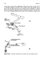
Special ends As required by design
FIGURE 20-11 Common-end configuration for helical extension springs. Recommended length is distance from last body coil
to inside of end. ID is inside diameter of adjacent coil in spring body. (Associated Spring, Barnes Group, Inc.)
FIGURE 20-12 Location of maximum bending and torsional stresses
in twist loops. (Associated Spring, Barnes Group, Inc.)
SPRINGS
20.27
Downloaded from Digital Engineering Library @ McGraw-Hill (www.digitalengineeringlibrary.com)
Copyright © 2004 The McGraw-Hill Companies. All rights reserved.
Any use is subject to the Terms of Use as given at the website.
SPRINGS
The maximum stress in torsion at point B (Fig. 20-12)
The constant C
2
in Eq. (20-78d)
For extension helical spring dimensions
FIGURE 20-13 Typical extension-spring dimensions. (Associated Spring, Barnes Group, Inc.)
For design equations of extension helical springs
The spring rate
The stress
CONICAL SPRINGS [Fig. 20-14(a)]
The axial deflection y for i coils of round stock may be
computed by the relation [Fig. 20-14(a)]
The axial deflection of a conical spring made of
rectangular stock with radial thickness b and an
axial dimension h [Fig. 20-14(c)]
For R
1
, refer to Fig. 20-12.
B
¼
8DF
d
3
4C
2
À 1
4C
2
À 4
ð20-78dÞ
C
2
¼
2R
2
d
ð20-78eÞ
For R
2
, refer to Fig. 10-12.
In practice C
2
may be taken greater than 4.
Refer to Fig. 20-13.
The design equations of compression springs may be
used.
k
0
¼
F À F
i
y
¼
Gd
4
8D
3
i
ð20-78fÞ
where F
i
¼ initial tension
¼
k8FD
d
3
ð20-78gÞ
where k ¼ stress factor for helical springs
Refer to Fig. 20-5 for k.
y ¼
2iFðD
3
2
þ D
2
2
D
1
þ D
2
D
2
1
þ D
3
1
Þ
d
4
G
ð20-79Þ
y ¼
iðD
3
2
þ D
2
2
D
1
þ D
2
D
2
1
þ D
3
1
Þ
4dD
2
kG
ð20-80Þ
y ¼
0:71iFðb
2
þ h
2
ÞðD
3
2
þ D
2
2
D
1
þ D
2
D
2
1
þ D
3
1
Þ
b
3
h
3
G
ð20-81Þ
Particular Formula
20.28 CHAPTER TWENTY
Downloaded from Digital Engineering Library @ McGraw-Hill (www.digitalengineeringlibrary.com)
Copyright © 2004 The McGraw-Hill Companies. All rights reserved.
Any use is subject to the Terms of Use as given at the website.
SPRINGS
NONMETALLIC SPRINGS
Rectangular rubber spring (Fig. 20-15)
Approximate overall dimension of the shock absorber
can be obtained by (Fig. 20-15)
Spring constant K of an absorber
Dimensions of sleeve and core are found by empirical
relations
FIGURE 20-15 Rectangular rubber spring.
TORSION SPRINGS (Fig. 20-16)
7
The maximum stress in torsion spring
The stress in torsion spring taking into consideration
the correction factor k
0
The deflection
The stress in round wire spring
FIGURE 20-14 Conical and volute springs.
L
D
2
¼
E
2F
2
U
ðF
max
=FÞ
2
À 1
ð20-82Þ
K ¼
D
2
E
L
ð20-83Þ
L
1
¼ 0:75L ð20-84Þ
D
1
¼ 0:70D ð20-85Þ
D
2
¼ 1:12D
1
ð20-86Þ
¼
M
t
Z
þ
F
A
ð20-87Þ
¼
k
0
M
t
Z
þ
2M
t
DA
ð20-88Þ
y ¼
M
t
LD
2EI
ð20-89Þ
¼
8M
t
ð4k
0
D þdÞ
d
3
D
ð20-89aÞ
where k
0
¼ k
1
can be taken from curve k
1
in Fig. 20.5
The torsional moment M
t
is numerically equal to
bending moment M
b
.
Particular Formula
SPRINGS
20.29
Downloaded from Digital Engineering Library @ McGraw-Hill (www.digitalengineeringlibrary.com)
Copyright © 2004 The McGraw-Hill Companies. All rights reserved.
Any use is subject to the Terms of Use as given at the website.
SPRINGS
The stress is also given by Eq. (20-90) without taking
into consideration the direct stress (F/A)
The expressions for k for use in Eq. (20-90)
Equation (20-90) for stress becomes
The angular deflection in radians
The spring rate of torsion spring
The spring rate can also be expressed by Eq. (20-95),
which gives good results
¼ k
M
b
c
I
ð20-90Þ
where M
b
¼ Fr
k ¼ k
o
¼
4C
2
þ C À1
4CðC þ 1Þ
for outer fiber ð20-91aÞ
k ¼ k
i
¼
4C
2
À C À1
4CðC À 1Þ
for inner fiber ð20-91bÞ
¼ k
i
32Fr
d
3
ð20-92Þ
¼
64M
b
Di
Ed
4
ð20-93Þ
k
0
¼
M
b
¼
d
4
E
64Di
ð20-94Þ
k
0
0
¼
d
4
E
10:8Di
ð20-95Þ
Particular Formula
FIGURE 20-16 Common helical torsion-spring end configurations. (Associated Spring, Barnes Group, Inc.)
20.30 CHAPTER TWENTY
Downloaded from Digital Engineering Library @ McGraw-Hill (www.digitalengineeringlibrary.com)
Copyright © 2004 The McGraw-Hill Companies. All rights reserved.
Any use is subject to the Terms of Use as given at the website.
SPRINGS
The allowable tensile stress for torsion springs
The endurance limit for torsion springs
Torsion spring of rectangular cross section
The stress in rectangular wire spring
Axial dimension b after keystoning
Another expression for stress for rectangular cross-
sectional wire torsion spring without taking into
consideration the direct stress ( ¼ F =A)
The spring rate
FIGURE 20-17 Torsion bar spring
Torsion bar springs
For allowable working stresses for rubber compres-
sion springs
sy
¼
a
¼
0:78
sut
cold-drawn carbon steel
0:87
sut
hardened and tempered
carbon and low-alloy
steels
0:61
sut
stainless steel
and nonferrous alloys
8
>
>
>
>
>
>
>
<
>
>
>
>
>
>
>
:
sf
¼ 538 MPa (78 kpsi)
¼
6k
0
M
t
b
2
h
þ
2M
t
Dbh
ð20-96Þ
where k
0
¼ k
2
can be taken from curve k
2
in Fig.
20-5
c ¼
D
h
ð20-97Þ
b
1
¼ b
C À 0:5
C
ð20-98Þ
¼
6k
i
M
b
bh
2
ð20-99Þ
where k
i
¼
4C
4C À 3
k
0
¼
M
b
¼
Ebh
3
66Di
ð20-100Þ
Refer to Tables 20-16 and 20-17 and Fig. 20-17.
Refer to Table 20-18.
Particular Formula
SPRINGS
20.31
Downloaded from Digital Engineering Library @ McGraw-Hill (www.digitalengineeringlibrary.com)
Copyright © 2004 The McGraw-Hill Companies. All rights reserved.
Any use is subject to the Terms of Use as given at the website.
SPRINGS
TABLE 20-16
Design formulas for bar springs
Cross section of
bar
Angular
deflection, ,rad
Maximum
shear stress,
Solid circular bar
584M
t
l
d
4
G
16M
t
d
3
Hollow circular
bar
584M
t
l
ðd
4
1
À d
4
2
G
16M
t
d
1
ðd
4
1
À d
4
2
Þ
Square bar
407M
t
l
b
4
G
4:81M
t
b
3
Rectangular bar
57:3M
t
l
k
0
1
bh
3
G
a
M
t
k
0
2
2bh
2
a
a
Values of k
0
1
and k
0
2
can be obtained from Table 20-9.
TABLE 20-17
Factors for computing rectangular bars in torsion
b=hk
0
k
0
1
k
0
2
1.0 0.675 0.140 0.208
1.2 0.759 0.166 0.219
1.5 0.848 0.196 0.231
2.0 0.930 0.229 0.246
2.5 0.968 0.249 0.258
3.0 0.985 0.263 0.267
4.0 0.997 0.281 0.282
5.0 0.999 0.291 0.291
10.0 1.000 0.312 0.231
1 1.000 0.333 0.333
TABLE 20-18
Suggested allowable working stresses for rubber compression springs
Limits of allowable stress
Occasional loading Cont. or freq. loading
b
Durometer hardness Area
a
ratio MPa psi MPa psi
30 5 2.76 400 0.97 140
30 3 2.48 360 0.93 135
30 2 2.24 325 0.86 125
30 1 1.79 260 0.73 105
30 0.5 1.45 210 0.62 90
50 4 4.82 700 1.86 270
50 2 3.73 540 1.58 230
50 1 2.69 390 1.24 180
50 0.5 2.07 300 1.03 150
80 2 6.13 890 2.69 390
80 1 4.14 600 2.07 300
80 0.5 2.90 420 1.65 240
a
Ratio of load-carrying area available for bulging or lateral expansion
20.32 CHAPTER TWENTY
Downloaded from Digital Engineering Library @ McGraw-Hill (www.digitalengineeringlibrary.com)
Copyright © 2004 The McGraw-Hill Companies. All rights reserved.
Any use is subject to the Terms of Use as given at the website.
SPRINGS
REFERENCES
1. Lingaiah, K. and B. R. Narayana Iyengar, Machine Design Data Handbook, Engineering College Co-
operative Society, Bangalore, India, 1962.
2. Lingaiah, K., and B. R. Narayana Iyengar, Machine Design Data Handbook, Vol. I (SI and Customary Metric
Units), Suma Publishers, Bangalore, India, 1986.
3. Lingaiah, K., Machine Design Data Handbook, Vol. II (SI and Customary Metric Units), Suma Publishers,
Bangalore, India, 1986.
4. SAE Handbook, Springs, Vol. I, 1981.
5. Maleev, V. L., and J. B. Hartman, Machine Design, International Textbook Company, Scranton,
Pennsylvania, 1954.
6. Wahl, A. M., Mechanical Springs, McGraw-Hill Book Company, New York, 1963.
7. Associated Spring, Barnes Group Inc., Bristol, CT, USA.
8. Jorres, R. E., Springs; Chap. 24 in J. E. Shigley and C. R. Mischke, eds., Standard Handbook of Machine
Design, McGraw-Hill Book Company, New York, 1986.
9. Shigley, J. E., and C. R. Mischke, Mechanical Engineering Design, 5th ed. McGraw-Hill Company, New York,
1989.
10. Zimmerli, F. P., Human Failures in Springs Applications, The Mainspring, No. 17, Associated Spring
Corporation, Bristol, Connecticut, Aug Sept. 1957.
11. Shigley, J. E., and C. R. Mischke, Standard Handbook of Machine Design, McGraw-Hill Book Company, New
York, 1986.
12. Phelan, R. M., Fundamentals of Mechanical Design, Tata-McGraw-Hill Publishing Company Ltd, New Delhi,
1975.
13. Lingaiah, K., Machine Design Data Handbook of Machine Design, 2nd edition, McGraw-Hill Publishing
Company, New York, 1996).
14. Shigley, J. E., and C. R. Mischke, Standard Handbook of Machine Design, 2nd edition, McGraw-Hill
Publishing Company, New York, 1996.
BIBLIOGRAPHY
Baumeister, T., ed., Marks’ Standard Handbook for Mechanical Engineers, McGraw-Hill Book Company, New
York, 1978.
Black, P. H., and O. Eugene Adams, Jr., Machine Design, McGraw-Hill Book Company, New York, 1968.
Bureau of Indian Standards.
Chironis, N. P., Spring Design and Application, McGraw-Hill Book Company, 1961.
Norman, C. A., E. S. Ault, and I. F. Zarobsky, Fundamentals of Machine Design, The Macmillan Company, New
York, 1951.
Shigley, J. E., Machine Design, McGraw-Hill Book Company, 1962.
SPRINGS 20.33
Downloaded from Digital Engineering Library @ McGraw-Hill (www.digitalengineeringlibrary.com)
Copyright © 2004 The McGraw-Hill Companies. All rights reserved.
Any use is subject to the Terms of Use as given at the website.
SPRINGS
CHAPTER
21
FLEXIBLE MACHINE ELEMENTS
SYMBOLS
11;12;13
a width of pulley face, m (in)
pivot arm length in Rockwood drive, m (in)
a
1
width of belt, m (in)
A ¼ 0:4ðd
2
=4Þ useful area of cross-section of the wire rope, m
2
(in
2
)
b thickness of arm, m (in)
dimension in Rockwood drive (Fig. 21-5), m (in)
c dimension in Rockwood drive (Fig. 21-5), m (in)
C center distance between sprockets (also with suffixes), m (in)
center distance between pulleys, m (in)
capacity of conveyor, m
3
(ft
3
)
constant depends on the rope diameter, sheave diameter, chain,
the bearing, and coefficient of friction [Eqs. (21-59) to (21-62)
and (21-86) to (21-103)] (also with suffixes)
C
1
tooth width in precision roller and bush chains, m (in)
d size of chain, m (in)
diameter of shaft, m (in)
diameter of idler bearing, m (in)
diameter of smaller pulley, m (in)
diameter of rope, m (in)
pitch diameter of sprocket, m (in)
d
1
diameter of small sprocket, m (in)
hub diameter of pulley, m (in)
d
2
diameter of large sprocket, m (in)
d
a
tip diameter of sprocket, m (in)
d
a1
tip diameter of small sprocket, m (in)
d
a2
tip diameter of large sprocket, m (in)
d
c
¼ f
p
F
b
equivalent pitch diameter, m (in)
d
f
root diameter of sprocket, m (in)
d
p
pitch diameter of the V-belt small pulley, m (in)
d
r
diameter of roller pin, m (in)
D pitch diameter of sheave, m (in)
diameter of large pulley, m (in)
wire rope drum diameter, m (in) (Fig. 21-4)
D
r
diameter of reel barrel, m (in) Eq. (21-76)
D
d
diameter of the drum in mm as measured over the outermost
layer filling the reel drum
21.1
Downloaded from Digital Engineering Library @ McGraw-Hill (www.digitalengineeringlibrary.com)
Copyright © 2004 The McGraw-Hill Companies. All rights reserved.
Any use is subject to the Terms of Use as given at the website.
Source: MACHINE DESIGN DATABOOK
D
o
diameter of the sheave pin, m (in)
e unit elongation of belt
E
0
corrected elasticity modulus of steel ropes
(78.5 GPa ¼11.4 Mpsi), GPa (psi)
F force, load, kN (lbf )
tension in belt, kN (lbf )
minimum tooth side radius, m (in)
F
a
correction factor for instructional belt service from Table 21-27
F
c
correction factor for belt length from Table 21-26
F
ct
centrifugal tension, kN (lbf )
F
d
correction factor for arc of contact of belt from Table 21-25
F
tangential force in the belt, required chain pull, kN (lbf )
F
s
tension due to sagging of chain, kN (lbf )
F
1
tension in belt on tight side, kN (lbf )
F
2
tension in belt on slack side, kN (lbf )
F
c
centrifugal force, kN (lbf)
values of coefficient for manila rope, Table 21-32
FR
1
the minimum value of tooth flank radius in roller and bush
chains, m (in)
FR
2
the maximum value of tooth flank radius in roller and bush
chains, m (in)
g acceleration due to gravity, 9.8066 m/s
2
(32.2 ft/s
2
)
G tooth side relief in bush and roller chain, m (in)
h the thickness of wall of rope drum, m (in)
crown height, m (in)
h
1
depth of groove in rope drum, m (in)
H ¼ðD
d
À D
r
Þ=2 depth of rope layer in reel drum, m (in)
i number of arms in the pulley,
number of V-belts,
number of strands in a chain,
transmission ratio
k ¼ðe
À 1Þ=e
variable in Eqs. (21-2d), (21-4a), (21-6), and (21-123), which
depends on ðz
1
À z
2
Þ=C
p
k
d
duty factor
k
l
load factor
K
min
center distance constant from Table 21-57
k
s
service factor
k
sg
coefficient for sag from Table 21-55
l width of chain or length of roller, m (in)
minimum length of boss of pulley, m (in)
minimum length of bore of pulley, m (in)
length of conveyor belt, m (in)
length of cast-iron wire rope drum, m (in)
outside length of coil link chain, m (in)
K
1
tooth correction factor for use in Eq. (21-116a)
K
2
multistrand factor for use in Eq. (21-116a)
L length of flat belt, m (in)
pitch length of V-belt, m (in)
rope capacity of wire rope reel, m (in)
L
p
length of chain in pitches
M
t
torque, N m (lbf in)
n number of times a rope passes over a sheave,
number of turns on the drum for one rope member
speed, rpm
factor of safety
21.2 CHAPTER TWENTY-ONE
FLEXIBLE MACHINE ELEMENTS
Downloaded from Digital Engineering Library @ McGraw-Hill (www.digitalengineeringlibrary.com)
Copyright © 2004 The McGraw-Hill Companies. All rights reserved.
Any use is subject to the Terms of Use as given at the website.
n
1
speed of smaller pulley, rpm or rps
speed of smaller sprocket, rpm or rps
n
2
speed of larger pulley, rpm or rps
speed of larger sprocket, rpm or rps
n
0
¼ nk
d
stress factor
P power, kW (hp)
P
T
power required by tripper, kW (hp)
p pitch of chain, m (in)
pitch of the grooves on the wire rope drum, m (in)
p
1
distance between the grooves of two-rope pulley, m (in)
P effort, load, kN (lbf)
P
b
bending load, kN (lbf)
P
s
service load, kN (lbf )
P
t
tangential force due to power transmission, kN (lbf )
P
u
ultimate load, kN (lbf)
breaking load, kN (lbf)
P
w
working load, kN (lbf )
Q load, kN (lbf)
r radius near rim (with subscripts), m (in)
radius, m (in)
s the amount of shift of the line of action of the load from the
center line on the raising load side of sheave, m (in)
s the average shift of the center line in the load on the effort side
of the sheave, m (in)
S the distance through which the load is raised, m (in)
SA
1
the minimum value of roller or bush seating angle, deg
SA
2
the maximum value of roller or bush seating angle, deg
SR
1
the minimum value of roller or bush seating radius, m (in)
SR
2
the maximum value of roller or bush seating radius, m (in)
t nominal belt thickness, m (in)
thickness of rim, m (in)
T tension in ropes, chains, kN (lbf)
TD
min
minimum limit of the tooth top diameter, m (in)
TD
max
maximum limit of the tooth top diameter, m (in)
v velocity of belt chain, m/s (ft/min)
w specific weight of belt, kN/m
3
(lbf/in
3
)
W width between reel drum flanges, m (in)
W
B
weight of belt, kN/m (lbf/in)
w
c
weight of chain, kN/m (lbf/in)
W
I
weight of revolving idler, kN/m (lbf/in) belt
W
L
load, kN/m (lbf/in)
z
1
number of teeth on the small sprocket
z
2
number of teeth on the large sprocket
stress, MPa (psi)
1
unit tension in belt on tight side, MPa (psi)
2
unit tension in belt on slack side, MPa (psi)
c
centrifugal force coefficient for leather belt, MPa (psi)
br
breaking stress for hemp rope, MPa (psi)
shear stress, MPa (psi)
arc of contact, rad
angle between tangent to the sprocket pitch circle and the
center line, deg
coefficient of friction between belt and pulley
coefficient of journal friction
c
coefficient of chain friction
FLEXIBLE MACHINE ELEMENTS 21.3
FLEXIBLE MACHINE ELEMENTS
Downloaded from Digital Engineering Library @ McGraw-Hill (www.digitalengineeringlibrary.com)
Copyright © 2004 The McGraw-Hill Companies. All rights reserved.
Any use is subject to the Terms of Use as given at the website.
efficiency
!
1
angular speed of small sprocket, rad/s
!
2
angular speed of large sprocket, rad/s
SUFFIXES
b bending
br breaking
t torque
c compressive
d design
min minimum
max maximum
Other factors in performance or in special aspects of design of flexible machine
elements are included from time to time in this chapter and being applicable only
in their immediate context, are not given at this stage.
BELTS
Flat belts
The ratio of tight side to slack side of belt at low
velocities
The power transmitted by belt
Power transmitted per m
2
(in
2
) of belt at low velocities
F
1
F
2
¼ e
ð21-1Þ
P ¼
F
v
1000c
s
SI ð21-2aÞ
where F
¼ F
1
À F
2
, P in kW, and v in m/s; F
in N
P ¼
F
v
33;000c
s
USCS ð21-2bÞ
where F
in lbf; P in hp; v in ft/min
P ¼
F
!r
1000c
s
SI ð21-2cÞ
where F
in N, P in kW, r in m, and ! in rad/s
Refer to Table 21-1 for c
s
.
P ¼
1
kv
1000
SI ð21-2dÞ
where k ¼ðe
À 1Þ=e
, and also from Table 21-2
1
in N/m
2
, v in m/s, and P in kW
P ¼
1
kv
33;000
USCS ð21-2eÞ
where
1
in psi, v in ft/min, and P in hp
Particular Formula
21.4 CHAPTER TWENTY-ONE
FLEXIBLE MACHINE ELEMENTS
Downloaded from Digital Engineering Library @ McGraw-Hill (www.digitalengineeringlibrary.com)
Copyright © 2004 The McGraw-Hill Companies. All rights reserved.
Any use is subject to the Terms of Use as given at the website.
TABLE 21-1
Service correction factors, c
s
Atmospheric condition Clean, scheduled maintenance on large drives 1.2
Normal 1.0
Oily, wet, or dusty 0.7
Angle of center line Horizontal to 608 from horizontal 1.0
608–758 from horizontal 0.9
758–908 from horizontal 0.8
Pulley material Fiber on motor and small pulleys 1.2
Cast iron or steel 1.0
Service Temporary or infrequent 1.2
Normal 1.0
Intermittent or continuous 0.8
Peak loads Light, steady load, such as steam engines, steam turbines, diesel engines, and
multicylinder gasoline engines
1.0
Jerky loads, reciprocating machines such as normal-starting-torque squirrel-
cage motors, shunt-wound, DC motors, and single-cylinder engines
0.8
Shock and reversing loads, full-voltage start such as squirrel-cage and
synchronous motors
0.6
TABLE 21-3
Values of coefficients
c
for leather belts for use in Eqs. (21-3) and (21-4)
Belt velocity, m/s (ft/min) 7.5 (1500) 10.0 (1950) 12.70 (2500) 15.0 (2950) 17.5 (3500) 20.0 (3950) 22.5 (4450) 25.0 (4950)
Coefficient,
c
, kgf/cm
2
0.57 1.05 1.63 2.35 3.10 4.07 5.14 6.36
MPa 0.0559 0.1030 0.1598 0.2305 0.3040 0.3991 0.5041 0.5237
psi 8.0 15.0 23.2 33.5 45.0 58.0 73.0 76.0
TABLE 21-2
Values of ðe
À 1Þ=e
¼ k for various coefficients of frictions and arcs of contact
Arc of contact between the belt and pulley (, deg)
Value of 90 100 110 120 130 140 150 160 170 180 200
0.28 0.356 0.387 0.416 0.444 0.470 0.496 0.520 0.542 0.564 0.585 0.502
0.30 0.376 0.408 0.438 0.467 0.494 0.520 0.544 0.567 0.590 0.610 0.553
0.33 0.404 0.438 0.469 0.499 0.527 0.554 0.579 0.602 0.624 0.645 0.684
0.35 0.423 0.457 0.489 0.520 0.548 0.575 0.600 0.624 0.646 0.667 0.705
0.38 0.449 0.485 0.518 0.549 0.578 0.605 0.630 0.654 0.676 0.697 0.735
0.40 0.467 0.502 0.536 0.567 0.597 0.624 0.649 0.673 0.695 0.715 0.753
0.43 0.491 0.528 0.562 0.593 0.623 0.650 0.676 0.699 0.721 0.741 0.777
0.45 0.507 0.544 0.579 0.610 0.640 0.667 0.692 0.715 0.737 0.757 0.792
0.48 0.529 0.567 0.602 0.634 0.663 0.690 0.715 0.738 0.759 0.779 0.813
0.50 0.544 0.582 0.617 0.649 0.678 0.705 0.730 0.752 0.773 0.792 0.825
0.53 0.565 0.603 0.638 0.670 0.700 0.726 0.750 0.772 0.793 0.811 0.843
FLEXIBLE MACHINE ELEMENTS
21.5
FLEXIBLE MACHINE ELEMENTS
Downloaded from Digital Engineering Library @ McGraw-Hill (www.digitalengineeringlibrary.com)
Copyright © 2004 The McGraw-Hill Companies. All rights reserved.
Any use is subject to the Terms of Use as given at the website.