Machine Design Databook Episode 3 part 1 doc
Bạn đang xem bản rút gọn của tài liệu. Xem và tải ngay bản đầy đủ của tài liệu tại đây (405.89 KB, 40 trang )
TABLE 23-2
Journal bearing design practices
Bearing modulus
(minimum)
Diameter
Maximum pressure, P clearance Viscosity,
1
Viscosity, S
00
¼
1
n
P
S
00
¼
n
0
P
ratio
Machinery Bearing kgf/mm
2
kpsi MPa ¼
c
d
Ratio
L
d
cP Pa s 10
3
USCSU
SI Units,
109
Automobile Main 0.56–1.19 0.8–1.7 5.50–11.70 — 0.1–1.8 7 7 15 36.3
and aircraft Crankpin 1.06–2.47 1.5–3.5 10.40–24.40 0.7–1.4 to to 10 24.2
engines Wrist pin 1.62–3.62 2.3–5.0 15.00–34.80 1.5–2.2 8 8 8 19.3
Gas and oil Main 0.49–0.85 0.7–1.2 4.85–8.35 0.001 0.6–2.0 20 20 20 48.4
engines (four- Crankpin 0.90–1.27 1.4–1.8 8.80–12.40 <0.001 0.6–1.5 to to 10 24.2
stroke) Wrist pin 1.27–1.55 1.8–2.2 12.40–15.20 <0.001 1.5–2.0 65 65 5 12.1
Gas and oil Main 0.35–0.56 0.5–0.8 3.42–5.50 0.001 0.6–2.0 20 20 25 60.4
engines (two- Crankpin 0.70–1.06 1.0–1.5 6.85–10.40 <0.001 0.6–1.5 to to 12 29.0
stroke) Wrist pin 0.85–1.07 1.2–1.8 8.35–12.50 <0.001 1.5–2.0 65 65 10 24.2
Marine steam Main 0.35 0.5 3.42 <0.001 0.7–1.5 30 30 20 48.4
engines Crankpin 0.42 0.6 4.14 <0.001 0.7–1.2 40 40 15 36.3
Wrist pin 1.06 1.5 10.40 <0.001 1.2–1.7 30 30 10 24.2
Stationary, Main 0.28 0.4 2.75 <0.001 1.0–2.0 60 60 20 48.4
slow-speed Crankpin 1.06 1.5 10.40 <0.001 0.9–1.3 80 80 6 14.5
steam engines Wrist pin 1.27 1.8 12.50 <0.001 1.2–1.5 60 60 5 12.1
Stationary, Main 0.17 0.25 1.66 <0.001 1.5–3.0 15 15 25 60.4
high-speed Crankpin 0.42 0.6 4.14 <0.001 0.9–1.5 30 30 6 14.5
steam engines Wrist pin 1.27 1.8 12.50 <0.001 1.3–1.7 25 25 5 12.1
Steam Driving axle 0.39 0.55 3.72 0.001 1.6–1.8 100 100 30 72.5
locomotives Crankpin 1.40 2.0 13.70 <0.001 0.7–1.1 40 40 5 12.1
Wrist pin 2.82 4.0 27.60 <0.001 0.8–1.3 30 30 5 12.1
Reciprocating Main 0.17 0.25 1.66 <0.001 1.0–2.2 30 30 30 72.5
pumps and Crankpin 0.42 0.6 4.14 <0.001 0.9–1.7 to to 20 48.4
compressors Wrist pin 0.70 1.0 6.85 <0.001 1.5–2.0 80 80 10 24.2
Railway cars Axle 0.35 0.45 3.42 0.001 1.8–2.0 100 100 50 120.9
Steam Main 0.07–0.19 0.1–0.275 0.69–1.87 0.001 1.0–2.0 2–16 2–16 100 241.8
turbines
Generators, Rotor 0.07-0.14 0.1-0.2 0.69-1.37 0.0013 1.0–2.0 25 25 200 483.5
motors,
centrifugal
pumps
Gyroscope Rotor 0.60 0.85 5.90 0.0013 — 30 30 55 133.0
Transmission Light, fixed 0.08 0.025 0.17 0.001 2.0–3.0 25 25 100 241.8
shafting Self-aligning 0.106 0.15 1.04 0.001 2.5–4.0 to to 30 72.5
Heavy 0.106 0.15 1.04 0.001 2.0–3.0 60 60 30 72.5
Cotton mill Spindle 0.0007 0.001 0.0069 0.005 — 2 2 10000 24177.5
Machine tools Main 0.21 0.3 2.06 0.001 1.0–1.4 40 40 40 96.7
Punching and Main 2.82 4.0 27.80 0.001 1.0–2.0 100 100 — —
shearing Crankpin 5.62 8.0 55.60 0.001 1.0–2.0 100 100 — —
machine
Rolling mills Main 2.11 3.0 20.60 0.0015 1.1–1.5 50 50 10 24.2
Key: ð
1
Þ¼absolute viscosity, Pa s (cP); n ¼ speed, rpm; n
0
¼ speed, rps; P ¼ pressure, N/m
2
or MPa (psi); MPa ¼megapascal ¼10
6
N/m
2
;Pa¼
Pascal ¼ 1 N/m
2
; 1 psi ¼ 6894.757 Pa; 1 kpsi ¼ 6.89475 MPa; USCSU ¼ US Customary System units.
DESIGN OF BEARINGS AND TRIBOLOGY 23.15
Downloaded from Digital Engineering Library @ McGraw-Hill (www.digitalengineeringlibrary.com)
Copyright © 2004 The McGraw-Hill Companies. All rights reserved.
Any use is subject to the Terms of Use as given at the website.
DESIGN OF BEARINGS AND TRIBOLOGY
TABLE 23-3
Values of factor C
1
in Eq. (23-23)
Lubrication Workmanship Attendance Operating condition Constant C
1
Oil bath or flooded High grade First class Clean and protected 1
Oil, free drop (constant feed) Good Fairly good Favorable (ordinary condition) 2
Oil cup or grease (intermittent
feed)
Fair Poor Exposed to dirt, grit or other
unfavorable conditions
4
TABLE 23-4
Values of factor C
2
in Eq. (23–23)
Type of bearing Constant C
2
Rotating journals, such as rigid bearing and crankpins 1
Oscillating journals, such as rigid wrist pin and Pintle blocks 1
Rotating bearings lacking ample rigidity, such as eccentric and the like 2
Rotating flat surfaces lubricated from the center to the circumference, such as annular step or pivot bearings 2
Sliding flat surfaces wiping over the guide ends, such as reciprocating crossheads; use 2 for relatively long
guides and 3 for short guides
2–3
Sliding or wiping surfaces lubricated from the periphery or outer wiping edge, such as marine thrust bearings
and worm gears
3–4
Long power-screw nuts and similar wiping parts over which it is difficult to effect a uniform distribution of
lubricant or load
4–6
r +
w
c
2
0
0
0
h
w
φ
B
A
D
E
e
e
(a) Stand still
r
0’
0’
0’
α’
β
ω
θ
r +
c
2
w
(b) At start
(c) Running
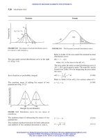
FIGURE 23-8 Behaviour of a journal in its bearing.
23.16 CHAPTER TWENTY-THREE
Downloaded from Digital Engineering Library @ McGraw-Hill (www.digitalengineeringlibrary.com)
Copyright © 2004 The McGraw-Hill Companies. All rights reserved.
Any use is subject to the Terms of Use as given at the website.
DESIGN OF BEARINGS AND TRIBOLOGY
BEARING PRESSURE (Fig. 23-9)
General Electric Company’s formula for bearing
pressure in the design of motor and generator bearing
Victor Tatarinoff’s equation for safe operating load
Victor Tatarinoff’s equation for permissible unit
pressure
P
a
¼ 6:2 10
5
3
ffiffiffiffiffiffi
v
m
p
SI ð23-24aÞ
where P
a
in N/m
2
and v
m
in m/s
P
a
¼ 15:5
3 ffiffiffiffiffiffi
v
m
p
USCS ð23-24bÞ
where P
a
in psi and v
m
in ft/min
P
a
¼ 0:0635
3 ffiffiffiffiffiffi
v
m
p
Customary Metric ð23-24cÞ
where P
a
in kgf/mm
2
and v
m
in m/s
W ¼
1
nd
3
ðL=dÞ
2
127ð10
6
Þh
1 þ
L
d
USCS ð23-25aÞ
where
1
in cP, n in rpm, L, d, h, and c in in, W in
lbf
W ¼
n
0
d
3
ðL=dÞ
2
0:295h
1 þ
L
d
SI ð22-25bÞ
where in Pa s, n
0
in rps, L, d, h, and c in m, W in N
P ¼
1
n
0
3175ð10
4
Þ
2
L
L þd
USCS ð23-26aÞ
where P in psi,
1
in cP, n in rpm, L and d in in
P ¼ 13:5
n
0
2
L
L þd
SI ð23-26bÞ
where P in Pa, in Pa s, n
0
in rps, and L and d in m
Particular Formula
Oil film
pressure
o
e
=
E
C
c
n
Without
groove
With
groove
d + c
Line of centers or
line joining 0 (centre
of bearing) and 0’
(centre of jouurnal)
I
L
θ
Pmax
P
max
φ
h
max
P
min
p
h
o
=
h
min
w
Bearing
Journal
Oil inlet
θ
PO
θ
FIGURE 23-9 Oil film pressure distribution in the full journal bearing.
DESIGN OF BEARINGS AND TRIBOLOGY
23.17
Downloaded from Digital Engineering Library @ McGraw-Hill (www.digitalengineeringlibrary.com)
Copyright © 2004 The McGraw-Hill Companies. All rights reserved.
Any use is subject to the Terms of Use as given at the website.
DESIGN OF BEARINGS AND TRIBOLOGY
H. F. Moore’s equation for critical pressure
The critical unit pressure for any given velocity should
not exceed according to Louis Illmer
Stribeck’s equation for the critical pressure when the
speed does not exceed 2.5 m/s (500 ft/min)
Stribeck’s equation for the critical pressure when the
speed exceeds 2.5 m/s (500 ft/min)
For permissible Pv values
For values S
00
for various combinations of journal
bearing materials, abrasion pressure for bearings,
allowable bearing pressures for semi-fluid lubricants
and diametral clearances in bearing dimensions.
P
c
¼ 7:23 10
5
ffiffiffi
v
p
SI ð23-27aÞ
where P
c
in N/m
2
and v in m/s
P
c
¼ 0:0737
ffiffiffi
v
p
Customary Metric ð23-27bÞ
where P
c
in kgf/mm
2
and v in m/s
P
c
¼ 7:5
ffiffiffi
v
p
USCS ð23-27cÞ
where P
c
in psi and v in ft/min
P
c
¼ 4:6 10
6
3
ffiffiffiffiffiffiffiffiffiffiffiffiffiffiffiffiffiffiffi
v
m
t 288:5
r
SI ð23-28aÞ
where P
c
in N/m
2
, v
m
in m/s, and t in K
P
c
¼ 0:47
3
ffiffiffiffiffiffiffiffiffiffiffiffiffiffiffiffi
v
m
t 15:5
r
Customary Metric ð23-28bÞ
where P
c
in kgf/mm
2
, v
m
in m/s, and t in 8C
P
c
¼ 140
3
ffiffiffiffiffiffiffiffiffiffiffiffiffiffiffiffi
v
m
t 15:5
r
USCS ð23-28cÞ
where P
c
in psi, v
m
in ft/min, t in 8F
P
c
¼ 9:7 10
5
ffiffiffi
v
p
SI ð23-28dÞ
where P
c
in N/m
2
and v in m/s
P
c
¼ 10
ffiffiffi
v
p
USCS ð23-28eÞ
where P
c
in psi and v in ft/min
P
c
¼ 0:0986
ffiffiffi
v
p
Customary Metric ð23-28f Þ
where P
c
in kgf/mm
2
and v in m/s
P
c
¼ 2:9 10
6
ffiffiffi
v
p
SI ð23-28gÞ
where P
c
in N/m
2
and v in m/s
P
c
¼ 30
ffiffiffi
v
p
USCS ð23-28hÞ
where P
c
in psi and v in ft/min
P
c
¼ 0:296
ffiffiffi
v
p
Customary Metric ð23-28iÞ
where P
c
in kgf/mm
2
and v in m/s
Refer to Table 23-5 for allowable pressures for reci-
procating motion.
Refer to Table 23-6.
Refer to Tables 23-7 to 23-10.
Particular Formula
23.18 CHAPTER TWENTY-THREE
Downloaded from Digital Engineering Library @ McGraw-Hill (www.digitalengineeringlibrary.com)
Copyright © 2004 The McGraw-Hill Companies. All rights reserved.
Any use is subject to the Terms of Use as given at the website.
DESIGN OF BEARINGS AND TRIBOLOGY
TABLE 23-5
Allowable bearing pressure, reciprocating motion
Pressure, P
Type of bearing Type of machinery psi MPa
Steam engine, stationary 35–60 0.24–0.412
Steam engine, marine 55–100 0.378–0.688
Crosshead
f
Steam engine, locomotive 70–90 0.48–0.62
Gas and oil engines, stationary 40–70 0.275–0.48
Compressors and pumps 50–90 0.342–0.62
Trunk pin
f
Gas and oil engines, stationary 20–25 0.136–0.172
Automotive and aircraft engines 25–40 0.172–0.275
TABLE 23-6
Permissible Pv values
Values
Class of bearing or journal psi ft/s N/m s
Mill shafting, with self-aligning cast-iron bearings, grease, or imperfect
oil-lubrication, maximum value
12,000 4.210
5
Mill shafting, self-aligning ring-oiled babbitt bearings, maximum 24,000 8.4510
5
Self-aligning ring-oiled bearings, continuous load in one direction 35,000–40,000 12.310
5
to 1410
5
Crankshaft journals with bronze bearings 22,000 7.710
5
Crankshaft bearings with babbitted bearings, maximum 59,000 20.810
5
For excellent radiating condition 133,000 46.510
5
Key: US Customary unit: P ¼ pressure, psi, v ¼ velocity, ft/s; SI unit: P ¼ pressure, N/m
2
, v ¼ velocity, m/s
TABLE 23-7
Values S
00
for various combinations of journal bearing materials
Bearing-modulus
S
00
¼
1
n
P
S
00
¼
n
0
P
Shaft Bearing Metric SI 10
9
Hardened and ground steel Babbitt 28,500 48.5
Machined, soft steel Babbitt 36,000 61.2
Hardened and ground steel Plastic bronze 42,700 72.6
Machined, soft steel Plastic bronze 35,800 60.9
Hardened and ground steel Rigid bronze 56,900 96.7
Machined, soft steel Rigid bronze 71,100 120.8
DESIGN OF BEARINGS AND TRIBOLOGY
23.19
Downloaded from Digital Engineering Library @ McGraw-Hill (www.digitalengineeringlibrary.com)
Copyright © 2004 The McGraw-Hill Companies. All rights reserved.
Any use is subject to the Terms of Use as given at the website.
DESIGN OF BEARINGS AND TRIBOLOGY
TABLE 23-8
Abrasion pressures for bearings
Pressure
Materials in contact psi MPa Remarks
Hardened tool steel on lumen or phosphor bronze 10,000 68.8 Values applies to rigid, polished and accurately
fitted rubbing surface
0.50 C machine steel on lumen or phosphor bronze 8,000 55.0 When not worn to a fit or well lubricated reduce
to 4.22 kgf/mm
2
(41.4 MPa)
Hardened tool steel on hardened tool steel 7,000 48.0
0.50 C machine steel or wrought iron on genuine
hard babbitt
6,000 41.5
Cast iron on cast iron (close grained or chilled) 4,500 31.0
Case-hardened machine steel on case-hardened
machine steel
4,000 27.5
0.30 C machine steel on cast iron (close-grained) 3,500 24.0
0.40 C machine steel on soft common babbitt 3,000 20.6
Soft machine steel on machine steel (not case- 2,000 13.8
hardened)
Machine steel on lignum vitae (water-lubricated) 1,500 10.2
TABLE 23-9
Allowable bearing pressures for semifluid lubrication
Allowable pressure, P
a
Bearing material Journal material psi MPa
Lumen of phosphor bronze Hardened tool steel 2500 17.30
Hardened steel Hardened alloy steel 2000 14.40
Hard babbitt SAE 1050 steel 1500 10.30
Bronze Hardened alloy steel 1300 8.90
Cast iron Cast iron 1100 7.58
Bronze Alloy steel 850 5.90
Babbit, soft SAE 1040 steel 750 5.20
Bronze Mild steel, smooth finish 540 3.70
Bronze Mild steel, ordinary finish 400 2.75
Bronze Cast iron 400 2.75
Cast iron Mild steel 350 2.40
Lignum vitae, water lubricated Mild steel 350 2.40
23.20 CHAPTER TWENTY-THREE
Downloaded from Digital Engineering Library @ McGraw-Hill (www.digitalengineeringlibrary.com)
Copyright © 2004 The McGraw-Hill Companies. All rights reserved.
Any use is subject to the Terms of Use as given at the website.
DESIGN OF BEARINGS AND TRIBOLOGY
IDEALIZED JOURNAL BEARING (Figs. 23-8
and 23-9)
The diametral clearance ratio or relative clearance
Attitude or eccentricity ratio or eccentricity coefficient
Oil film thickness at any position
For position of minimum oil thickness and max oil
film pressure
Minimum oil film thickness
The minimum oil film thickness variable
¼
c
d
ð23-29Þ
" ¼
2e
c
¼ 1
2h
min
d
ð23-30Þ
Refer to Fig. 23-10 for ".
h ¼
c
2
ð1 þ " cos Þð23-31Þ
Refer to Figs. 23-11 and 23-11A
h
min
¼ h
o
¼
c
2
ð1 "Þð23-32Þ
¼
2h
min
c
¼ð1 "Þð23-33Þ
Refer to Figs. 23-12 to 23-14 and 23-15 for .
Particular Formula
TABLE 23-10
Diametral clearance in bearings dimension in micrometers (1 lm ¼ 10
6
m)
Diametral clearances, c in lm
Particular about bearing and journal d ¼ 12 d ¼ 25 d ¼ 50 d ¼ 100 d ¼ 140
Precision spindle, hardened and ground steel, lapped into bronze
bearingv
m
< 25 m/s; P < 500 psi (3.43 N/m
2
); 0.2–0.4 mmrms
7–19 19–38 38–63 63–88 88–125
Precision spindle, hardened and ground steel, lapped into bronze
bearingv
m
> 25 m/s; P > 500 psi (3.43 N/m
2
); 0.2–0.4 mmrms
13–25 25–50 50–75 75–113 113–163
Electric motors and generators, ground journals i n broached or
reamed bronze or babbitt bearings; 0.4–0.8 mmrms
13–38 25–50 38–85 50–100 75–150
General machinery, intermittent or continuous motion, turned or
cold-rolled journal in reamed and bored bronze or babbitt
bearings; 0.8–1.5 mmrms
50–100 63–113 75–125 100–175 125–200
Rough machinery, turned or cold-rolled steel journals in poured
babbitt bearings; 1.5–3.8 mmrms
77–150 125–225 200–300 275–400 350–500
Automotive crankshaft
Babbitt-lined bearing 38 63
Cadmium silver copper 50 75
Copper lead 36 88
DESIGN OF BEARINGS AND TRIBOLOGY
23.21
Downloaded from Digital Engineering Library @ McGraw-Hill (www.digitalengineeringlibrary.com)
Copyright © 2004 The McGraw-Hill Companies. All rights reserved.
Any use is subject to the Terms of Use as given at the website.
DESIGN OF BEARINGS AND TRIBOLOGY
0
0
0
.
2
0
.
4
0
.
6
0
.
8
1
.
0
0.10 0.20 0.30 0.40
Attitude, ε
0
0
0
.
2
0
.
4
0
.
6
0
.
8
1
.
0
0.010 0.020 0.030 0.040
Attitude, ε
Reynolds
Petroff
Lightly loaded bearing
Beyond this point
S =
1
59
.
36
Bearing characteristic number, S =
ηn
P
1
ψ
2
(a) Moderately and lightly loaded
bearing
Bearing characteristic number, S =
ηn’
P
1
ψ
2
(b) Heavily loaded bearing
FIGURE 23-10 Variation of attitude " of full journal bearing with characteristic number S. [Radzimosvksy
4
]
0
0
10
20
30
40
50
60
70
80
90
100
0.01 0.02 0.04 0.060.080.1 0.2 0.4 0.6 0.81.0 2 4 6 8 10
Bearing Characteristic Number, S =
ηn’
P
1
ψ
2
Position of Minimum Oil Film
Thickness, deg
φ
L
d
= ∞
1
2
1
4
1
FIGURE 23-11 Position of minimum oil film thickness vs. bearing characteristic number S for full journal bearing. (Refer to
Fig. 23-9 for definition of .) [Boyd and Raimondi
5
]
23.22
Downloaded from Digital Engineering Library @ McGraw-Hill (www.digitalengineeringlibrary.com)
Copyright © 2004 The McGraw-Hill Companies. All rights reserved.
Any use is subject to the Terms of Use as given at the website.
DESIGN OF BEARINGS AND TRIBOLOGY
0
0
0
.
2
0
.
4
0
.
6
0
.
8
1
.
0
12 46
810
246
810
2
246
810
3
BEARING CHARACTERISTIC NUMBER S’ =
60ηn’
P
1
ψ
2
MINIMUM FILM THICKNESS VARIABLE, δ
FIGURE 23-12 Minimum oil film thickness variable based on no side flow. [Boyd and Raimondi
5
]
0
0
0
.
1
0
.
2
0
.
3
0
.
4
0
.
5
0
.
6
0
.
7
0
.
8
0
.
9
1
.
0
0
.
10 0
.
20 0
.
30
BEARING CHARACTERISTIC NUMBER
ηn’
P
1
ψ
2
S =
REYNOLDS
PETROFF
LIGHTLY LOADED
BEARING
2n
min
c
δ =
FIGURE 23-13 Variation of minimum oil film thickness variable of full journal bearing with S.
23.23
Downloaded from Digital Engineering Library @ McGraw-Hill (www.digitalengineeringlibrary.com)
Copyright © 2004 The McGraw-Hill Companies. All rights reserved.
Any use is subject to the Terms of Use as given at the website.
DESIGN OF BEARINGS AND TRIBOLOGY
The safe oil film thickness for a bearing in good
condition and v
m
1 m/s (200 ft/min)
The thickness of oil film where the pressure is maxi-
mum or minimum
The resultant pressure distribution around a journal
bearing excluding P
o
the oil film pressure at the
point where ¼ 0or ¼ 2
The pressure at any point (Figs. 23-8 and 23-9)
The load carrying capacity of the bearing [Fig. 23-8
(panel c)]
The bearing characteristic number or Sommerfeld
number
For Sommerfeld number S
h
min
¼ h
o
¼ 2:37 10
5
v
0:4
m
A
0:2
SI ð23-34aÞ
where h
min
in m, A in m
2
, and v
m
in m/s
h
min
¼ 0:0015v
0:4
m
A
0:2
Customary Metric ð23-34bÞ
where h
min
in mm, A in mm
2
, and v
m
in m/s
h
min
¼ 0:000026v
0:4
m
A
0:2
USCS ð23-34cÞ
where h
min
in in, A in in
2
, and v
m
in in
ðhÞ
PðmaxÞ
¼ k ¼
2cð1 "
2
Þ
2 þ"
2
ð23-35Þ
PðminÞ
P
r
¼ðP P
o
Þ
¼
12U
2
d
"ð2 þ" cos Þsin
ð2 þ"
2
Þð1 þ" cos Þ
2
ð23-36Þ
P ¼ P
r
þ P
o
ð23-37Þ
W ¼
UL
2
2"
ð2 þ"
2
Þ
ffiffiffiffiffiffiffiffiffiffiffiffiffi
2 "
2
p
!
ð23-38Þ
S ¼
n
0
P
1
2
ð23-39Þ
Refer to Tables 23-10 to 23-12 for Sommerfeld
numbers S for full and partial bearings.
0
040
60 S
C
L
10
6
MINIMUM FILM THICKNESS VARIABLE, δ
80
VALUE OF
120 160 200 240 280 320 360
0
.
2
0
.
4
0
.
6
0
.
8
1
.
0
FIGURE 23-14 Variation of minimum oil film thickness variable with S=C
L
.
Particular Formula
23.24 CHAPTER TWENTY-THREE
Downloaded from Digital Engineering Library @ McGraw-Hill (www.digitalengineeringlibrary.com)
Copyright © 2004 The McGraw-Hill Companies. All rights reserved.
Any use is subject to the Terms of Use as given at the website.
DESIGN OF BEARINGS AND TRIBOLOGY
0
0 0.01 0.02 0.04 0.06
ηn’
P
0.08 0.1 0.2 0.4 0.6 0.8 1.0 2 4 6 8 10
0.1
Bearing Characteristic Number, S = ( )
0.2
0.3
0.4
0.5
0.6
0.7
0.8
0.9
1.0
0
0.1
0.2
0.3
0.4
0.5
0.6
0.7
0.8
0.9
1.0
Optimum Boundary
1
1
2
1
4
L
d
= ∞
M
a
x
i
m
u
m
L
o
a
d
M
i
n
i
m
u
m
F
r
i
c
t
i
o
n
1
ψ
2
2e
c
Attitude or Eccentricity Ratio, ε =
2h
min
c
Minimum Oil Film Thickness Variables, δ =
FIGURE 23-15 Variation of minimum oil film thickness variable and attitude " of full journal bearing with bearing characteristic number S. [Boyd and
Raimondi
5
]
DESIGN OF BEARINGS AND TRIBOLOGY 23.25
Downloaded from Digital Engineering Library @ McGraw-Hill (www.digitalengineeringlibrary.com)
Copyright © 2004 The McGraw-Hill Companies. All rights reserved.
Any use is subject to the Terms of Use as given at the website.
DESIGN OF BEARINGS AND TRIBOLOGY
The constant of the bearing or bearing modulus
The calculation of minimum oil film thickness from
Figs 23-14 and 23-16
The bearing characteristic number or Sommerfeld
number as a function of attitude
The angular positions of points where the maximum
or minimum pressure in the oil film occur [Fig. 23-8c
and Fig. 23-9]
For positions of maximum oil film pressure and oil
film termination vs. bearing characteristic number S
S
00
¼
n
P
ð23-40Þ
where in Pa s (cP)
Refer to Table 23-7 for bearing modulus.
Hint: S is determined from Eq. (23-39) and C
L
from
Fig. 23-16 for a given ðL=dÞ ratio. Calculate
60S=ðC
L
10
6
Þ. Knowing 60S=ðC
L
10
6
Þ, you can then
obtain the minimum film thickness variable from
Fig. 23-14. From and Eq. (23-33), you can then
determine the minimum oil film thickness.
S ¼
ð2 þ"
2
Þ
ffiffiffiffiffiffiffiffiffiffiffiffiffi
1 "
2
p
12
2
"
ð23-41Þ
Refer to Fig. 23-10 for " for various values of S.
¼ cos
1
3"
"
2
þ 2
ð23-42Þ
Refer to Fig. 23-15A.
Particular Formula
L
d
= ∞
1
2
L
d
1
4
1
4
1
2
I
∞
=
0
Po
0
0.01
0.02
0.04 0.06 0.08 0.1
Bearing Characteristic Number , S =
0.2 0.4 0.6 0.8 1.0
2
246810
0
5
10
15
20
25
10
20
30
40
50
Terminating Position of Oil Film, deg
60
70
80
90
100
θ
Po
θ
deg
Pmax
θ
Pmax
θ
n’
P
1
η
Angular Position of Maximum Oil Film
Pressure,
ψ
1
FIGURE 23-15A Position of maximum oil film pressure and oil film termination versus bearing characteristic number S. [Boyd
and Raimondi
24
] (Refer to Fig. 23-9 for definition of
P
max
, and
P
0
.)
23.26 CHAPTER TWENTY-THREE
Downloaded from Digital Engineering Library @ McGraw-Hill (www.digitalengineeringlibrary.com)
Copyright © 2004 The McGraw-Hill Companies. All rights reserved.
Any use is subject to the Terms of Use as given at the website.
DESIGN OF BEARINGS AND TRIBOLOGY
TABLE 23-11
Dimensionless performance parameters for full journal bearings with side flow
Values of
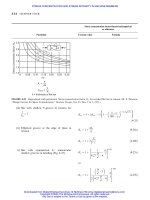
L=d ratio 0.25 0.5 1.0 1
For maximum load 0.27 0.43 0.53 0.66
For minimum friction 0.03 0.12 0.3 0.6
L
d
"S
4Q
d
2
n
0
L
Q
s
Q
c
sp
T
0
P
P
P
max
0.25 0 1.0 1 (89.5) 1 0 1 —
0.1 0.9 16.2 82.31 322.0 3.45 0.180 1287.0 0.515
0.2 0.8 7.57 75.18 153.0 3.76 0.330 611.0 0.489
0.4 0.6 2.83 60.86 61.1 4.37 0.567 245.0 0.415
0.6 0.4 1.07 46.72 26.7 4.99 0.746 107.6 0.334
0.8 0.2 0.261 31.04 8.80 5.60 0.884 35.4 0.240
0.9 0.1 0.0736 21.85 3.50 5.91 0.945 14.1 0.180
0.97 0.03 0.0101 12.22 0.922 6.12 0.984 3.73 0.108
1.0 0 0 0 0 — 1.0 0 0
0.5 0 1.0 1 (88.5) 1 0 1 —
0.1 0.9 4.31 81.62 85.6 3.43 0.173 343.0 0.523
0.2 0.8 2.03 74.94 40.9 3.72 0.318 164.0 0.506
0.4 0.6 0.779 61.45 17.0 4.29 0.552 68.6 0.441
0.6 0.4 0.319 48.14 8.10 4.85 0.730 33.0 0.365
0.8 0.2 0.0923 33.31 3.26 5.41 0.874 13.4 0.267
0.9 0.1 0.0313 23.66 1.60 5.69 0.939 6.66 0.206
0.97 0.03 0.00609 13.75 0.610 5.88 0.980 2.56 0.126
1.0 0 0 0 0 — 1.0 0 0
101.01 (85) 1 0 1 —
0.1 0.9 1.33 79.5 26.4 3.37 0.150 106 0.540
0.2 0.8 0.631 74.02 12.8 3.59 0.280 52.1 0.529
0.4 0.6 0.264 63.10 5.79 3.99 0.497 24.3 0.484
0.6 0.4 0.121 50.58 3.22 4.33 0.680 14.2 0.415
0.8 0.2 0.0446 36.24 1.70 4.62 0.842 8.0 0.313
0.9 0.1 0.0188 26.45 1.05 4.74 0.919 5.16 0.247
0.97 0.03 0.00474 15.47 0.514 4.82 0.973 2.61 0.152
1.0 0 0 0 0 — 1.0 0 0
1 01.01 (70.92) 1 0 1 —
0.1 0.9 0.240 69.10 4.80 3.03 0 19.9 0.826
0.2 0.8 0.123 67.26 2.57 2.83 0 11.4 0.814
0.4 0.6 0.0626 61.94 1.52 2.26 0 8.47 0.764
0.6 0.4 0.0389 54.31 1.20 1.56 0 9.73 0.667
0.8 0.2 0.021 42.22 0.961 0.760 0 15.9 0.495
0.9 0.1 0.0115 31.62 0.756 0.411 0 23.1 0.358
0.97 0.03 — — — — 0 — —
1.0 0 0 0 0 0 0 1 0
Key: Q
s
¼ flow of lubricant with side flow, cm
3
/s; ¼ weight per unit volume of lubricant whose specific gravity is 0.90 ¼ 8.83 kN/m
3
(0.0325 lbf/
in
3
); c
sp
¼ specific heat of the lubricant, kJ/NK (Btu/lbf 8F) ¼ 0.19 kJ/NK (0.42 Btu/lbf 8F); T
0
¼ difference in temperature, 8C.
Source: A. A. Raim ondi and J. Boyd, ‘‘A Solution for the Finite Journal Bearings and Its Applications to Analysis and Design’’ ASME, J. Lubri-
cation Technol., Vol. 104, pp. 135–148, April 1982.
DESIGN OF BEARINGS AND TRIBOLOGY 23.27
Downloaded from Digital Engineering Library @ McGraw-Hill (www.digitalengineeringlibrary.com)
Copyright © 2004 The McGraw-Hill Companies. All rights reserved.
Any use is subject to the Terms of Use as given at the website.
DESIGN OF BEARINGS AND TRIBOLOGY
TABLE 23-12
Dimensionless performance parameters for 1808 bearing centrally loaded with side flow
a
Values of
L=d ratio 0.25 0.5 1.0 1
For maximum load 0.28 0.42 0.52 0.64
For minimum friction 0.03 0.23 0.44 0.60
L
d
"S
4Q
d
2
n
0
L
Q
s
Q
c
sp
T
0
P
P
P
max
0.25 0 1.0 1 90.0 1 0 1 —
0.1 0.9 16.3 81.40 163.0 3.44 0.176 653.0 0.513
0.2 0.8 7.60 73.70 79.4 3.71 0.320 320.0 0.489
0.4 0.6 2.84 58.99 35.1 4.11 0.534 146.0 0.417
0.6 0.4 1.08 44.96 17.6 4.25 0.698 79.8 0.336
0.8 0.2 0.263 30.43 6.88 4.07 0.837 36.5 0.241
0.9 0.1 0.0736 21.43 2.99 3.72 0.905 18.4 0.180
0.97 0.03 0.0104 12.28 0.877 3.29 0.961 6.46 0.110
1.00 0 0 0— 1.0 00
0.50 0 1.0 1 90.0 1 0 1 —
0.1 0.9 4.38 79.97 44.0 3.41 0.167 177.0 0.518
0.2 0.8 2.06 72.14 21.6 3.64 0.302 87.8 0.499
0.4 0.6 0.794 58.01 9.96 3.93 0.506 42.7 0.438
0.6 0.4 0.321 45.01 5.41 3.93 0.665 25.9 0.365
0.8 0.2 0.0921 31.29 2.54 3.56 0.806 15.0 0.273
0.9 0.1 0.0314 22.80 1.38 3.17 0.886 9.80 0.208
0.97 0.03 0.00635 13.63 0.581 2.62 0.951 5.30 0.132
1.00 0 0 0— 1.0 00
101.01 90.0 — 0 1 —
0.1 0.9 1.40 78.50 14.1 3.34 0.139 57.0 0.525
0.2 0.8 0.670 68.93 7.15 3.46 0.252 29.7 0.513
0.4 0.6 0.278 58.86 3.61 3.49 0.425 16.5 0.466
0.6 0.4 0.128 44.67 2.28 3.25 0.572 12.4 0.403
0.8 0.2 0.0463 32.33 1.39 2.63 0.721 10.4 0.313
0.9 0.1 0.0193 24.14 0.921 2.14 0.818 9.13 0.244
0.97 0.03 0.00483 14.57 0.483 1.60 0.915 6.96 0.157
1.0 0 0 0 0 — 1.0 0 0
1 01.01 90.0 1 11 —
0.1 0.9 0.347 72.90 3.55 3.04 0 14.7 0.778
0.2 0.8 0.179 61.32 2.01 2.80 0 8.99 0.759
0.4 0.6 0.898 49.99 1.29 2.20 0 7.34 0.700
0.6 0.4 0.0523 43.15 1.06 1.52 0 8.71 0.607
0.8 0.2 0.0253 33.35 0.859 0.767 0 14.1 0.459
0.9 0.1 0.0128 25.57 0.681 0.380 0 22.5 0.337
0.97 0.03 0.00384 15.43 0.416 0.119 0 44.0 0.190
1.0 0 0 0 0 0 0 1 0
a
See Key and Source under Table 23-11.
23.28 CHAPTER TWENTY-THREE
Downloaded from Digital Engineering Library @ McGraw-Hill (www.digitalengineeringlibrary.com)
Copyright © 2004 The McGraw-Hill Companies. All rights reserved.
Any use is subject to the Terms of Use as given at the website.
DESIGN OF BEARINGS AND TRIBOLOGY
TABLE 23-13
Dimensionless performance parameters for 1208 for centrally loaded bearing with side flow
a
Values of
L=d ratio 0.25 0.5 1.0 1
For maximum load 0.26 0.38 0.46 0.53
For minimum friction 0.06 0.28 0.4 0.5
L
d
" S
4Q
d
2
n
0
L
Q
s
Q
c
sp
T
0
P
P
P
max
0.25 0 1.0 1 90.0 1 0 1 —
0.10 0.9044 18.4 76.97 124.0 3.34 0.143 502.0 0.456
0.20 0.8011 8.45 65.97 60.4 3.44 0.260 254.0 0.438
0.40 0.6 3.04 51.23 26.6 3.42 0.442 125.0 0.389
0.6 0.4 1.12 40.42 13.5 3.20 0.599 75.8 0.321
0.8 0.2 0.268 28.38 5.65 2.67 0.753 42.7 0.237
0.9 0.1 0.0743 20.55 2.63 2.21 0.846 25.9 0.178
0.97 0.03 0.0105 12.11 0.852 1.69 0.931 11.6 0.112
1.0 0 0 0 0 — 1.0 0
0.50 0 1.0 1 90.0 1 0——
0.1 0.9034 5.42 74.99 36.6 3.29 0.124 149.0 0.431
0.2 0.8003 2.51 63.38 18.1 3.32 0.225 77.2 0.424
0.4 0.6 0.914 48.07 8.20 3.15 0.386 40.5 0.389
0.6 0.4 0.354 38.50 4.43 2.80 0.530 27.0 0.336
0.8 0.2 0.0973 28.02 2.17 2.18 0.684 19.0 0.261
0.9 0.1 0.0324 21.02 1.24 1.70 0.787 15.1 0.203
0.97 0.03 0.00631 13.00 0.550 1.19 0.899 10.6 0.136
1.0 0 0 0 0 — 1.0 0 0
101.0 1 90.0 1 0 1 —
0.1 0.9024 2.14 72.43 14.5 3.20 0.0876 59.5 0.427
0.2 0.8 1.01 58.25 7.44 3.11 0.157 32.6 0.420
0.4 0.6 0.385 43.98 3.60 2.75 0.272 19.0 0.396
0.6 0.4 0.162 35.65 2.16 2.24 0.384 15.0 0.356
0.8 0.2 0.0531 27.42 1.27 1.57 0.535 13.9 0.290
0.9 0.1 0.0208 21.29 0.855 1.11 0.657 14.4 0.233
0.97 0.03 0.00498 13.49 0.461 0.694 0.812 14.0 0.162
1.0 0 0 0 0 — 1.0 0 0
1 01.0 1 90.0 1 0 1 —
0.1 0.9007 0.877 66.69 6.02 3.02 0 25.1 0.610
0.2 0.8 0.431 52.60 3.26 2.75 0 14.9 0.599
0.4 0.6 0.181 39.02 1.78 2.13 0 10.5 0.566
0.6 0.4 0.0845 32.67 1.21 1.47 0 10.3 0.509
0.8 0.2 0.0328 26.80 0.853 0.759 0 14.1 0.405
0.9 0.1 0.0147 21.51 0.653 0.388 0 21.2 0.311
0.97 0.03 0.00406 13.86 0.399 0.118 0 42.3 0.199
1.0 0 0 0 0 0 0 1 0
a
See Key and Source under Table 23-11.
DESIGN OF BEARINGS AND TRIBOLOGY 23.29
Downloaded from Digital Engineering Library @ McGraw-Hill (www.digitalengineeringlibrary.com)
Copyright © 2004 The McGraw-Hill Companies. All rights reserved.
Any use is subject to the Terms of Use as given at the website.
DESIGN OF BEARINGS AND TRIBOLOGY
TABLE 23-14
Dimensionless performance parameters for 608 centrally loaded bearing with side flow
a
Values of
L=d ratio 0.25 0.5 1.0 1
For maximum load 0.15 0.20 0.23 0.25
For minimum friction 0.10 0.16 0.22 0.23
L
d
" S
4Q
d
2
n
0
L
Q
s
Q
c
sp
T
0
P
P
P
max
0.25 0 1.0 1 90.0 1 0 1 —
0.1 0.9251 35.8 71.55 121.0 3.16 0.0666 499.0 0.251
0.2 0.8242 16.0 58.51 58.7 3.04 0.131 260.0 0.249
0.4 0.6074 5.20 41.01 24.5 2.57 0.236 136.0 0.242
0.6 0.4 1.65 30.14 11.2 1.98 0.346 86.1 0.228
0.8 0.2 0.333 21.70 4.27 1.30 0.496 54.9 0.195
0.9 0.1 0.0844 16.87 2.01 0.894 0.620 41.0 0.159
0.97 0.03 0.0110 10.81 0.713 0.507 0.786 29.1 0.107
1.00 0 0 0— 1.0 00
0.5 0 1.0 1 90.0 1 0 1 —
0.1 0.9223 14.2 69.00 48.6 3.11 0.0488 201.0 0.239
0.2 0.8152 6.47 52.60 24.2 2.91 0.0883 109.0 0.239
0.4 0.6039 2.14 37.00 10.3 2.38 0.160 59.4 0.233
0.6 0.4 0.695 26.98 4.93 1.74 0.236 40.3 0.225
0.8 0.2 0.149 19.57 2.02 1.05 0.350 29.4 0.201
0.9 0.1 0.0422 15.91 1.08 0.664 0.464 26.5 0.172
0.97 0.03 0.00704 10.85 0.490 0.329 0.650 27.8 0.122
1.00 0 0 0— 1.0 00
101.0 1 90.0 1 0 1 —
0.1 0.9212 8.52 67.92 29.1 3.07 0.0267 121.0 0.252
0.2 0.8133 3.92 50.96 14.8 2.82 0.0481 67.4 0.251
0.4 0.6010 1.34 33.99 6.61 2.22 0.0849 39.1 0.247
0.6 0.4 0.450 24.56 3.29 1.56 0.127 28.2 0.239
0.8 0.2 0.101 18.33 1.42 0.883 0.200 22.5 0.220
0.9 0.1 0.0309 15.33 0.822 0.519 0.287 23.2 0.192
0.97 0.03 0.00584 10.88 0.422 0.226 0.465 30.5 0.139
1.00 0 0 0— 1.0 00
1 01.0 1 90.0 1 0 1 —
0.1 0.9191 5.75 65.91 19.7 3.01 0 82.3 0.337
0.2 0.8109 2.66 48.91 10.1 2.73 0 46.5 0.336
0.4 0.6002 0.931 31.96 4.67 2.07 0 28.4 0.329
0.6 0.4 0.322 23.21 2.40 1.40 0 21.4 0.317
0.8 0.2 0.0755 17.39 1.10 0.722 0 19.2 0.287
0.9 0.1 0.0241 14.94 0.667 0.372 0 22.5 0.243
0.97 0.03 0.00495 10.58 0.372 0.115 0 40.7 0.163
1.0 0 0 0 0 0 0 1 0
a
See Key and Source under Table 23-11.
23.30 CHAPTER TWENTY-THREE
Downloaded from Digital Engineering Library @ McGraw-Hill (www.digitalengineeringlibrary.com)
Copyright © 2004 The McGraw-Hill Companies. All rights reserved.
Any use is subject to the Terms of Use as given at the website.
DESIGN OF BEARINGS AND TRIBOLOGY
The total frictional resistance on an idealized journal
bearing surface
The total frictional resistance on an idealized lightly
loaded journal bearing
For the relation between dimensionless quantity
n
0
F
0
1
and Sommerfeld numbers S
F
¼
4UL
1 þ2"
2
ð2 þ"
2
Þ
ffiffiffiffiffiffiffiffiffiffiffiffiffi
1 "
2
p
!
ð23-43Þ
or
F
¼
4
2
n
0
Ldð1 þ 2"
2
Þ
ð2 þ"
2
Þ
ffiffiffiffiffiffiffiffiffiffiffiffiffi
1 "
2
p
ð23-44Þ
F
¼
2
2
n
0
Ld
ð23-45Þ
Refer to Fig. 23-17.
Particular Formula
0
01 234
2
Ratio, L/d
4
Factor C
L
6
8
10
FIGURE 23-16 Variation of factor C
L
with L=d
ratio.
Petroff
0
0
0
.
01
0
.
11
.
50
.
20
.
3
0
.
02
0
.
03
0
.
04
0
.
05
0
.
06
ηn’
P
Bearing characteristic number, S =
ηn’
Fµ’
1
ψ
2
1
ψ
FIGURE 23-17 Variation of dimensionless
quantity
1
n
0
F
0
with Sommerfeld number S for
an idealized full journal bearing.
DESIGN OF BEARINGS AND TRIBOLOGY
23.31
Downloaded from Digital Engineering Library @ McGraw-Hill (www.digitalengineeringlibrary.com)
Copyright © 2004 The McGraw-Hill Companies. All rights reserved.
Any use is subject to the Terms of Use as given at the website.
DESIGN OF BEARINGS AND TRIBOLOGY
The relation between coefficient of friction and bear-
ing characteristic number
The relation between the coefficient of friction and
attitude "
For average coefficient of friction at very high
pressures
The friction coefficient variable
¼ 2
2
n
0
P
1
ð23-46Þ
¼
1 þ2"
2
3"
ð23-47Þ
Refer to Table 23-15 for coefficient of friction
¼
¼
1 þ2"
2
3"
ð23-48Þ
Refer to Figs. 23-20 to 23-24.
Particular Formula
TABLE 23-15
Average coefficient of friction at very high pressure
Angular displacement, deg
Material 108 508
Stearic acid 0.022 0.029
Tungsten disulphide 0.032 0.037
Molybdenum disulphide 0.032 0.033
Graphite 0.036 0.058
Silver sulphate 0.055 0.054
Turbine oil plus 1% MoS
2
0.060 0.068
Lead iodide 0.061 0.071
Palm oil 0.063 0.075
Castor oil 0.064 0.081
Grease (zinc-oxide base) 0.071 0.080
Lard oil 0.072 0.084
Grease (calcium base) 0.073 0.082
Residual 0.076 0.083
Sperm oil 0.077 0.085
Turbine oil plus 1% graphite 0.081 0.105
Turbine oil plus 1% stearic acid 0.087 0.096
Turbine oil 0.088 0.108
Capric acid 0.089 0.109
Turbine oil plus 1% mica 0.091 0.105
Oleic acid 0.093 0.119
Machine oil 0.099 0.115
Soapstone (powdered) 0.169 0.306
Mica (powdered) 0.257 0.305
Boron (not a lubricant) 0.482 0.710
23.32 CHAPTER TWENTY-THREE
Downloaded from Digital Engineering Library @ McGraw-Hill (www.digitalengineeringlibrary.com)
Copyright © 2004 The McGraw-Hill Companies. All rights reserved.
Any use is subject to the Terms of Use as given at the website.
DESIGN OF BEARINGS AND TRIBOLOGY
INFLUENCE OF MISALIGNMENT OF
SHAFT IN BEARING
Minimum oil film thickness corresponding to the
materials factor (k
m
), the surface roughnesses (R
p
)
and amount of misalignment of the journal and bear-
ing (M
a
)
Dimensionless oil feed rate
h
min
¼ k
m
ðR
pj
þ R
pb
Þþ
M
a
L
2
ð23-48aÞ
where k
m
¼ material factor from Table 23-15a
L ¼ length of bearing
R
pb
¼ surface roughness of bearing from
Table 23-15b
M
a
¼ x=L amount of misalignment
Refer to Table 23-15c and Fig. 23-18 for M
a
Q
0
¼
2Q
Ldn
0
c
ð23-48bÞ
where Q in m
3
/s, L, d, and c in m, n
0
in rps
Particular Formula
TABLE 23-15a
Material factor, k
m
Bearing lining material k
m
Phosphor bronze 1
Leaded bronze 0.8
Tin aluminium 0.8
White metal (Babbitt) 0.5
Thermoplastic (bearing grade) 0.6
Thermosetting plastic 0.7
Courtesy: Neale, M. J., Tribology Handbook, Newnes-Butterworths,
1973
TABLE 23-15c
Values of misalignment factor, M
a
at two ratios of
(h
min
=c)
(h
min
=c)
M
a
(L=c) 0.1 0.01
0 100 100
0.05 65 33
0.25 25 7
0.50 12 3
0.75 8 1
Courtesy: Neale, M. J., Tribology Handbook, Newnes-Butterworths,
1973
TABLE 23-15b
Surface finish, predominant peak height, R
p
Micro-inch lm
R
p
Surface type cla RMS Class lm lin
Turned or rough
ground
100 2.8 6 12 480
Ground or fine
bored
20 0.6 8 3 120
Fine ground 7 0.19 10 0.8 32
Lapped or
polished
1.5 0.04 12 0.2 9
Courtesy: Neale, M. J., Tribology Handbook, Newnes-Butterworths,
1973
d
x
y
L
M
a
=
x
y
FIGURE 23-18 Misaligned journal inside the bearing
under load
DESIGN OF BEARINGS AND TRIBOLOGY
23.33
Downloaded from Digital Engineering Library @ McGraw-Hill (www.digitalengineeringlibrary.com)
Copyright © 2004 The McGraw-Hill Companies. All rights reserved.
Any use is subject to the Terms of Use as given at the website.
DESIGN OF BEARINGS AND TRIBOLOGY
Bearing load capacity number
The required grease supply rate per hour for grease
lubricated bearing
The coefficient of friction
The diameter of journal bearing for speeds below
2.5 m/s
The diameter of journal bearing for speeds exceeding
2.5 m/s
POWER LOSS
The power loss in the bearing due to viscous friction
W
0
¼
W
e
n
0
Ld
2
ð23-48cÞ
where W
0
ðd=LÞ
2
¼ dimensionless load number,
W in N, n
0
in rps,
e
in N s/m
2
, L, d,andc in m
Q
g
¼ k
g
c dL ð23-48dÞ
where k
g
¼ a factor for grease lubrication at
various rotational speeds.
Taken from Table 23-15d.
¼
ð23-48eÞ
where
¼ =
d ¼ 3:2 10
3
5
ffiffiffiffiffiffiffiffi
W
2
i
2
n
0
s
ð23-48fÞ
where W in N, d in m; l=d ¼ i and n
0
in rps
d ¼ 2 10
3
7
ffiffiffiffiffiffiffiffi
W
2
i
3
n
0
s
ð23-48gÞ
P ¼
F
U
33;000
USCS ð23-49aÞ
where P in hp, F
in lbf, and U in ft/min
P ¼
F
U
102
Customary Metric ð23-49bÞ
where P in kW, F
in kgf, U ¼ dn
0
¼ velocity in
m/s, d in m, and n
0
in rps
P ¼
F
U
1000
SI ð23-49cÞ
where P in kW, F
in N, and U in m/s
Particular Formula
TABLE 24-15d
Values of factor k
g
for grease lubrication at
various rotational speeds
Journal speed, n in rpm k
g
up to 100 0.1
250 0.2
500 0.4
1000 1.0
Courtesy: Neale, M. J., Tribology Handbook, Newnes
Butterworth
b
d
Lubricant feed rate Q
Diametrical clearance C
d
Lubricant viscosity η
e
w
n’
FIGURE 23-19 Journal inside the bearing under Load (W)
at speed (n
0
).
23.34 CHAPTER TWENTY-THREE
Downloaded from Digital Engineering Library @ McGraw-Hill (www.digitalengineeringlibrary.com)
Copyright © 2004 The McGraw-Hill Companies. All rights reserved.
Any use is subject to the Terms of Use as given at the website.
DESIGN OF BEARINGS AND TRIBOLOGY
60 Partial journal bearings
0
0
0
0
5
10
15
0
.
05
0
.
51
.
01
.
52
.
0
Coefficient of friction variable,
0
.
10 0
.
15 0
.
20
1
2
3
4
5
B/L = 4
.
0
B/L = 3
.
0
B/L = 2
.
0
B/L = 1
.
0
B/L = 0
ηn’
P
Bearing characteristic number, S =
µ
1
ψ
2
ηn’
P
Bearing characteristic number, S =
1
ψ
2
ψ
Coefficient of friction variable,
µ
ψ
60 Partial journal bearings
B/L = 4
.
0
B/L = 3
.
0
B/L = 2
.
0
B/L = 1
.
0
B/L = 0
FIGURE 23-20 Variation of coefficient of friction variable = with S for 608
partial journal bearing.
120 Partial journal bearings
0
0
10
20
0
0
0
.
05
0
.
51
.
01
.
52
.
0
Coefficient of friction variable,
0
.
10 0
.
15 0
.
20
1
2
3
4
B/L = 4
.
0
B/L = 3
.
0
B/L = 2
.
0
B
/L =
1
.
0
B/L = 0
ηn’
P
Bearing characteristic number, S =
µ
1
ψ
2
ηn’
P
Bearing characteristic number, S =
1
ψ
2
ψ
Coefficient of friction variable,
µ
ψ
120 Partial journal bearings
B
/L = 4
.
0
B/L = 3
.
0
B/L = 2
.
0
B/L = 1
.
0
B
/L =
0
FIGURE 23-21 Variation of coefficient of friction variable = with S for 1208
partial journal bearing.
23.35
Downloaded from Digital Engineering Library @ McGraw-Hill (www.digitalengineeringlibrary.com)
Copyright © 2004 The McGraw-Hill Companies. All rights reserved.
Any use is subject to the Terms of Use as given at the website.
DESIGN OF BEARINGS AND TRIBOLOGY
B/L = 0
B/L = 1
.
0
B/L = 2
.
0
B/L =
3
.
0
B/L = 4
.
0
180 Partial journal bearings
0
0
10
20
30
0
.
51
.
01
.
52
.
0
0
1
2
3
4
5
0
.
05 0
.
10 0
.
15 0
.
20
Coefficient of friction variable,
µ
ψ
Coefficient of friction variable,
µ
ψ
ηn’
P
1
ψ
2
Bearing characteristic number, S =
ηn’
P
1
ψ
2
Bearing characteristic number, S =
180 Partial Journal bearings
B/L = 1
.
0
B/L = 2
.
0
B/L = 3
.
0
B/L = 4
.
0
B/L = 0
FIGURE 23-22 Variation of coefficient of friction variable = with S for 1808
partial journal bearing.
360 Journal bearings
360 Journal bearings
B/L = 0
B/L = 1
.
0
B/L = 2
.
0
B/L = 3
.
0
B/L = 4
.
0
0
0
10
20
30
40
45
0
.
51
.
01
.
52
.
0
0
1
.
0
2
.
0
3
.
0
4
.
0
5
.
0
6
.
0
6
.
5
0
.
05 0
.
10 0
.
15 0
.
20
PETROFF
Coefficient of friction variable,
µ
ψ
µ
ψ
Coefficient of friction variable,
µ
ψ
ηn’
P
1
ψ
2
Bearing characteristic number, S =
ηn’
P
1
ψ
2
Bearing characteristic number, S =
B/L = 4
.
0
B/L = 3
.
0
B/L = 2
.
0
PETROFF
= 2 π
2
s
FIGURE 23-23 Variation of coefficient of friction variable = with S for 3608 par-
tial journal bearing.
23.36
Downloaded from Digital Engineering Library @ McGraw-Hill (www.digitalengineeringlibrary.com)
Copyright © 2004 The McGraw-Hill Companies. All rights reserved.
Any use is subject to the Terms of Use as given at the website.
DESIGN OF BEARINGS AND TRIBOLOGY
PARTIAL JOURNAL BEARING (Fig. 23-25)
The resultant pressure distribution around the partial
journal bearing excluding, P
o
oil film pressure at the
point where ¼ 0
P
r
¼ P P
o
ð23-50Þ
where
P P
o
¼
12U
2
d
ð1 "
2
Þð2 þ "
2
Þðk=cÞ
ð1 "
2
Þ
2=5
arc tan
ffiffiffiffiffiffiffiffiffiffiffi
1 "
1 þ "
r
tan
2
!
þ
ðk=2cÞ" sin
2ð1 "
2
Þð1 þ" cos Þ
2
þ
" sin fð3k=2cÞ2ð1 "
2
Þg
2ð1 "
2
Þ
2
ð1 þ" cos Þ
where k ¼ h is the thickness of oil film at maximum
pressure value
Particular Formula
L
d
=
4
1
∞
1
2
0
0 0.01 0.02
Coefficient of Friction Variable, λ
µ
= µ/ψ
0.04 0.06 0.08 0.1 0.2 0.4 0.60.81.0 2 4 6 8 10
1
2
3
4
5
10
2
3
4
5
10
2
2
1
P
Bearing Characteristic Number, S = ( )
1
ηn’
ψ
2
FIGURE 23-24 Variation of the coefficient of friction variable
¼ = with S for 3608 journal bearing. [Boyd and Raimondi
5
]
DESIGN OF BEARINGS AND TRIBOLOGY
23.37
Downloaded from Digital Engineering Library @ McGraw-Hill (www.digitalengineeringlibrary.com)
Copyright © 2004 The McGraw-Hill Companies. All rights reserved.
Any use is subject to the Terms of Use as given at the website.
DESIGN OF BEARINGS AND TRIBOLOGY
Pressure at any point in a partial journal bearing
To determine the attitude " and attitude angle for
various values of S and for an idealized offset partial
bearing having the maximum load capacity corre-
sponding to a given attitude
INFLUENCE OF END LEAKAGE
Leakage factors C
W
, C
F
, and C
P ¼ P
o
þ P
r
ð23-51Þ
Refer to Figs. 23-26 and 23-27 respectively.
Refer to Fig. 23-28 for C
W
, C
F
, and C
for various
values of B=L ratios
Particular Formula
Journal
Bearing
Leading
edge
O’
w,
B
e = cε
β
φ
θ
α
A
n
O
d
d + c
Pressure
distribution
Trailing
edge
Line of
centers
h
o
= h
min
P
max
h’
max
h’
max
FIGURE 23-25 Partial journal bearing.
0
0
0
.
2
0
.
10
Attitude, ε
0
.
20 0
.
30
0
.
4
0
.
6
0
.
8
1
.
0
ηn’
P
Bearing characteristic number, S =
1
ψ
2
FIGURE 23-26 Variation of attitude " with S for an idealized offset
partial bearing having the maximum load capacity corresponding to a
given attitude.
0
00
.
1
Attitude angle φ, deg
0
.
20
.
30
.
40
.
50
.
6
10
20
30
40
50
60
70
80
90
ηn’
P
Bearing characteristic number, S =
1
ψ
2
FIGURE 23-27 Variation of attitude angle with S for
an idealized offset partial bearing.
23.38 CHAPTER TWENTY-THREE
Downloaded from Digital Engineering Library @ McGraw-Hill (www.digitalengineeringlibrary.com)
Copyright © 2004 The McGraw-Hill Companies. All rights reserved.
Any use is subject to the Terms of Use as given at the website.
DESIGN OF BEARINGS AND TRIBOLOGY
Load leakage factor according to Kingsbury
6
Load leakage factor C
W
as a function of B=L ratio for
a slider bearing having q ¼ðh
1
=h
2
Þ1 ¼ 1or
h
1
¼ 2h
2
Load leakage factor for 1208, centrally loaded partial
bearing according to Needs
7
Load correction factor for side flow according to
Boyd and Raimondi
24
Coefficient of friction leakage factor according to
Kingsbury
6
Friction leakage factor according to Kingsbury
6
Friction leakage factor for 1208, centrally loaded
partial bearing according to Needs
7
C
W
¼
W
W
1
ð23-52Þ
Refer to Fig. 23-28 for C
W
.
Refer to Table 23-16.
Refer to Fig. 23-29 for C
W
for various attitudes ".
Refer to Fig. 23-30 for C
W
for various minimum oil
film thickness variables .
C
¼
1
ð23-53Þ
Refer to Fig. 23-28 for C
C
F
¼
F
F
1
ð23-54Þ
Refer to Fig. 23-28 for C
F
.
Refer to Fig. 23-31 for C
F
for various attitudes ".
Particular Formula
C
F
C
W
C
µ
0
0
0
.
1
0
.
51
.
0
Leakage factors C
W
, C
F
, and C
µ
1
.
5
Length in direction of motion
Length in direction perpendicular to motion
B
L
2
.
02
.
53
.
02
.
54
.
0
0
.
2
0
.
3
0
.
4
0
.
5
0
.
6
0
.
7
0
.
8
0
.
9
1
.
0
=
FIGURE 23-28 Kingsbury’s leakage factors as function of B=L
ratios under minimum friction. [Kingsbury
6
]
TABLE 23-16
Load leakage factor C
W
as a function of B=L ratio
for a slider bearing having the quality q equal to
unity
B=LC
W
B=LC
W
0.00 1.00 1.00 0.44
0.175 0.92 1.50 0.278
0.25 0.835 2.00 0.185
0.50 0.68 3.00 0.090
0.75 0.55 4.00 0.060
DESIGN OF BEARINGS AND TRIBOLOGY
23.39
Downloaded from Digital Engineering Library @ McGraw-Hill (www.digitalengineeringlibrary.com)
Copyright © 2004 The McGraw-Hill Companies. All rights reserved.
Any use is subject to the Terms of Use as given at the website.
DESIGN OF BEARINGS AND TRIBOLOGY