Machinery Components Maintenance And Repair Episode 2 Part 11 doc
Bạn đang xem bản rút gọn của tài liệu. Xem và tải ngay bản đầy đủ của tài liệu tại đây (283.43 KB, 25 trang )
cylinder, and under the constant sliding of adjacent metal parts, like piston
rings. This phenomenon of oil retention is termed “wettability” and
describes the dispersive characteristics of oil on a microscopically uneven
metal surface.
The oil collects in the recesses of the metal surface and disperses
outward in an enveloping movement. In contrast, the surface tension of
oil will cause an oil drop on a smooth plane surface to exhibit a tendency
to reach a state of equilibrium where it will neither spread nor recede, and
thus does not provide a lubricating coating for that surface. Such a surface
inside a cylinder liner will not be adequately covered with an oil film and
will require greater volumes of lube oil to achieve adequate protection
from friction, temperatures, corrosion, and abrasion.
This proprietary porous chrome surface prevents the action of the
oil’s molecular cohesion in trying to achieve a perfect sphere, and form-
ing into a drop. The configuration of the chrome surface disrupts this
tendency.
This porous chrome presents such a varied surface that a portion of
the area
1
/
4
in. in diameter may contain from 50 to several hundred pores
or crevices depending on the porosity pattern applied to the chrome
surface. Even one drop of oil, encountering such a surface, tends to
disperse itself indefinitely over the flats, downslopes of pores, and the
upsloping side.
The importance of lubrication has been discussed in numerous books,
and a direct correlation between a successfully maintained oil film and
wear on piston rings and liner surfaces can be shown. Thus, the ability of
porous chrome surfaces to provide an unbroken oil film indicates its desir-
ability in preventing many types of liner wear, including gas erosion,
which is due to a leaky piston ring seal; friction and frictional oxidation,
by protecting the surface from oxygen in the combustion area; preventing
metal stresses resulting in abrasion from excessive loading, which does
not break the oil film maintained by the chrome; and by protecting the
surface from corrosive agents produced by lube oil breakdown and com-
bustion products.
The load capacity of porous chrome involves a condition known as
boundary-layer lubrication. This term refers to an oil film thickness
that is so thin it approaches the characteristics of dry lubrication. It has
lost its mobility as a fluid, but reduces the mutual attraction of adjacent,
sliding metallic surfaces, and thereby the friction. Fluid lubrication, e.g.,
thicker layers of lube oil, are not desired under the high-temperature
conditions of the combustion area of the cylinder, because of the sus-
ceptibility of lube oil to flash point combustion, breakdown into deposits,
unnecessarily high lube oil consumption, and the production of air
pollutants.
Protecting Machinery Parts Against Loss of Surface 565
566 Machinery Component Maintenance and Repair
Thermal Conductivity
Thermal conductivity in chromium is higher than for cast iron and com-
monly used steels, by approximately 40 percent, as shown in Table 10-6.
Maximum metal surface temperatures in the cylinder are at the liner
surface, especially in the combustion zone, and any improvement in heat
transfer provides a lower wall temperature and will improve piston and
ring lubrication. The heat reflection qualities of chromium add to the com-
bustion and exhaust temperatures, helping to reduce incomplete combus-
tion and its products.
While the coefficient of expansion, also shown in Table 10-6, of
chromium is lower than that of cast iron or steel, there is a decided advan-
tage in the difference. The surface of the cylinder liner has a much higher
temperature than the underlying basis metal, because of that sharp tem-
perature gradient through the wall. The effect of this gradient on a
homogeneous metal, e.g., distortion, is eliminated with chromium plating,
because it is desirable to have a variable coefficient of expansion ranging
from a lower value at the inner wall surface to a higher value in the
outer wall, where the coolants are operating. Tests run on air-cooled
airplane engines for 700 to 1,000 hours showed no tendency of the
chromium surfaces to loosen due to differential expansion between the
chrome and the basis metal. This is significant, considering that these
engines normally run at higher cylinder wall temperatures than engines in
stationary installations.
Table 10-6
Expansion Coefficients and Thermal Conductivity
Thermal
Linear thermal conductivity
expansion cal/cm
2
/cm/
in./in. at 68°F deg C/sec at
Metal (¥10
-6
) 20°C Melting point, F°
Chromium, electrolytic 4.5 0.165 3,325+
Cast iron 6.6 0.12 2,500
Steels 6.2–6.6 0.11 2,700–2,800
Aluminum 12–13 0.52 1,216
Copper 9.1 0.92 1,981
Protecting Machinery Parts Against Loss of Surface 567
Abrasion Resistance
Wear rates for chromium are substantially lower than for cast iron, as
the data in Tables 10-7 and 10-8 show. The data were developed in a test
of two engines run for nine hours under load, with one a cast iron cylin-
der and the other a porous-chrome surfaced cylinder. Allis-Chalmers Type
B abrasive dust (85 percent below five microns, 100 percent below 15
microns) was added to the initial charge of crankcase oil, with a propor-
tion of abrasive dust of 8.6 percent by weight of the lube oil, to acceler-
ate wear.
Table 10-7
Cylinder Wear
Diametral wear, in.
Wear ratio,
Cast-iron Porous-chrome cast-iron cyl./
Location cylinder cylinder porous-chrome cyl.
1
/
8
in. below head end 0.0077 0.0018 4.3–1
1
/
2
in. below head end 0.0071 0.0021 3.4–1
2 in. below head end 0.0083 0 0022 3.8–1
Table 10-8
Piston and Ring Wear
In porous-chrome
In cast iron cylinder cylinder
Wear ratio,
Percent of Percent of cast-iron cyl./
original original porous-chrome
Grams weight Grams weight cylinder
Aluminum piston loss
in weight 0.589 0.90 0.316 0.45 1.9 : 1
Top ring lost
in weight 2.506 56.0 0.849 18.9 3.0 : 1
Second ring loss
in weight 2.586 57.8 0.972 21.8 2.6 : 1
Oil ring loss
in weight 1.260 46.5 0.865 31.9 1.5 : 1
568 Machinery Component Maintenance and Repair
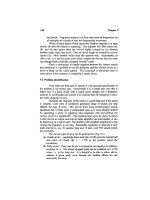
The constrast in wear ratios between the cast iron and chromium in this
test is substantial, reaching as much as four to one in the cylinder and
three to one for the pistons and rings. Figure 10-10 shows a plot of these
data for the cylinder wear comparison
9
.
Often, the boring out of worn cylinders requires the deposition of extra-
thick layers of chrome to bring the surface back to standard size. This is
not advisable, because on the next resalvaging, it may not be possible to
bore down further into the basis metal and still retain enough structural
strength in the liner wall to justify salvaging.
With another proprietary process, 99.9 percent pure iron is electro-
deposited on the basis metal with a special bond, to build up the basis metal,
to a thickness where normal chrome layer thicknesses are practical.
Chromium in Turbocharged Engines
The operation of turbocharged engines involves the exaggeration of all
the wear factors described in this section because the temperatures are
higher, fuel and lube oil consumption are higher, the engine runs faster,
and corrosive agents seem to be more active and destructive. Turbo-
charging, however, increases the horsepower of an engine from 10 to 25
percent. During the last decade, many stationary engines were retrofitted
for turbocharging, and engines with liners not surfaced with chrome have
had the chance to be upgraded.
Just as an example, the high heat of turbocharged engines creates a
lubrication problem with cast iron liner surfaces. Even microporosity in
Figure 10-10. Cylinder wear on chrome and cast-iron cylinders.
Protecting Machinery Parts Against Loss of Surface 569
iron casting will not retain oil under such high temperatures. The corre-
sponding increase in wear factor effects will accelerate liner and piston
ring wear and increase downtime.
Special chromium, with variable porosity tailored to the operating char-
acteristics of the engine, can make the difference between a productive
engine installation and a liability.
Operating Verification
In a detailed study assessing the conditions and circumstances
influencing machinery maintenance on motor ships, Vacca
10
plots the
operating performance of several marine engine liners and arrives at a
documented conclusion that chrome-plated liners show a wear rate that
is less than half that of nonchrome-plated liners. The indirect result is
considerable improvement in fuel economy and ship speed. Figure 10-11
shows these data plots.
Another application study emphasized the benefits of chrome-plating
engine liners and was seen to have a direct effect on labor requirements
and the workloading of engine room staffs.
For more documented low wear rates, a study on engine liner perfor-
mance by Dansk-Franske Dampskibsselskab of Copenhagen on one
of their ships, the “Holland,” produced some interesting statistics. All
Figure 10-11. Graphs of cylinder liner wear. Curves A and C refer to opposed piston engines
and curves B, D, and E are for poppet valve engines. Curves D and E show results using
chromium plated liners.
570 Machinery Component Maintenance and Repair
cylinder liners were preventive plated with chromium before they were
installed. The results well repaid the effort, in less overhaul, reduced ring
wear, and extremely low cylinder wear. The highest wear rates on the six
cylinder liners were 0.20 mm/10,000 hours, as shown on the chart in
Figure 10-12. This negligible wear led to the conclusion that the liners:
“ will still have a life of more than 10,000 hours In fact, it means
that this ship will never need any liner replacement.”
11
Even though these studies represented only a fraction of the operating
and test data that supports this contention, they indicate the considerable
benefits in terms of cost-savings and long-lived performance that the
use of chrome-plating can provide. The fact that the studies cited were
performed on motor ships, in salt-water environments, where corrosion
agents are more active than in stationary facilities, adds further emphasis
to this position.
The question of chrome plating economy has been raised and can be
answered by an example. Chrome-plating offers a twofold economy. First,
in the cost of restandardizing with chrome over the cost of a new liner,
and second, the extended length of operating life of the plated liner,
whether new or reconditioned.
Figure 10-12. Cylinder liner wear—with chrome plating.
Protecting Machinery Parts Against Loss of Surface 571
As stated in the Diesel Engineering Handbook:
“A (chrome) plating will cost 65 to 75 percent of the price of a new
unplated cast iron liner, or 50 to 60 percent of the price of a new
chrome-plated liner. It must be remembered that the plated liner will
have three to five times the life of a new unplated liner.”
12
The significance of the last sentence in the quote is often overlooked.
Even if the chrome-plating restandardsizing of the worn liner were 100
percent of the cost of a new unplated liner, a cost savings will be achieved
because the replated liner will still last three to five times as long. At 100
percent, the replated liner is thus still only about 30 percent of the cost of
all the new replacement liners that would be required to match its normal
operating life.
Conclusion
Our principal conclusions can be summarized as follows. Directly or
indirectly, all of the effects of the wear factors described in this section
can be mitigated or eliminated completely with the use of special
chromium-plating on cylinder liners, crankshafts, and piston rods.
Whether the method of liner salvage is restandardsizing or oversize
boring with oversize piston rings, or even with new liners and parts to be
conditioned for long wear before going into service, proprietary chromium
plating processes can add years of useful operating life in a continuing,
cost effective solution to the problems of wear.
On-Site Electroplating Techniques. Where parts cannot be moved to a
plating work station, deposition of metal by the brush electroplating
technique may be considered.* This process serves the same varied func-
tions that bath electroplating serves. Brush electroplating of machinery
components is used for corrosion protection, wear resistance, improved
solderability or brazing characteristics and the salvaging of worn or mis-
matched parts. Housed in a clean room, the equipment needed for the
process is:
1. The power pack.
2. A lathe.
3. Plating tools.
* Dalic Plating Process.
4. Masking equipment and plating solutions.
5. Drip retrieval tray.
6. Pump to return solutions through a filter to the storage bath.
7. Trained operator.
8. Supply of clean water for rinsing parts between plating operations.
Brush electroplating thickness in excess of 0.070 in. is generally more
economic if done in a plating bath.
Electrochemical metallizing, another form of electroplating, is a hybrid
between electric arc welding and bath electroplating. It is a portable
system for adding metal to metal. As a special type of metallizing, the
process is claimed to offer better adhesion, less porosity, and more precise
thickness control than conventional flame spray or plasma types of met-
allizing. Unlike conventional metallizing or bulk welding, the base metal
is not heated to high temperatures, thus avoiding thermal stresses.
In the rebuilding of main bearing saddle caps—a typical application—
one flexible lead is connected to a working tool or “stylus” of appropri-
ate size and shape. The stylus serves as an anode, and is wrapped in an
absorbent material. The absorbent is a vehicle for the aqueous metallic
plating solution. Metal deposits rapidly onto the cathodic—negative
charged—workpiece surface. Deposit rates of 0.002 in. per minute are
typical. One repair shop uses multistep processes in which the prepared
metal surface initially is built to approximate dimensions with a heavy-
build alkaline copper alloy solution. Then a hardened outer surface is
created by depositing a tungsten alloy from a second solution.
Not only engine saddle caps, but cylinder heads, crankcases, manifolds,
engine blocks, crankshafts, and other machinery castings have been suc-
cessfully repaired using the electrochemical metallizing process. The
process has replaced conventional oxyacetylene high-heat bronze welding
that was used to build new metal onto worn saddle caps. The high-heat
welding associated with oxyacetylene spraying had disadvantages in terms
of excessive machining time, metal waste, lost time in cool-down, and
high temperature distortion of the workpiece.
In field use, the hardness and durability of electrochemically metallized
material appears to equal the original casting. In contrast to other metal
rebuilding methods, flaking or cracking of parts rebuilt with the process
has not been experienced
13
.
The following equipment is required for an electrochemical plating
process
14
:
1. The power pack and flexible leads.
2. Turning heads and assorted stylus tools. The turning head is a low
speed reversible, variable speed rotational device for use in electro-
572 Machinery Component Maintenance and Repair
chemically plating cylindrical components. It enables rotation of
shafts, bearings and housings, so that either inside or outside
diameters can be uniformly plated.
3. Handles and selected anodes.
4. Accessories such as cotton batting, wrapping material, stylus
holders, evaporating dishes, solution pump, and tubing.
5. Selection of plating solutions from some 100 different primary
metals or alloy solutions.
6. A trained operator.
Hardening of Machinery Components. In trying to achieve improved
wear resistance it would be well not to neglect proven traditional steel-
hardening methods. In surface hardening of alloy steels the core of a
machinery part may be treated to produce a desired structure for machin-
ability or a strength level of service, whereas the surface may be subse-
quently hardened for high strength and wear resistance.
Flame hardening involves very rapid surface heating with a
direct high temperature flame, followed by cooling at a suitable rate
for hardening. The process utilizes a fuel gas plus air or oxygen for
heating.
Steels commonly flame hardened are of the medium, 0.30 to 0.60
percent carbon range with alloy suitable for the application. The quench-
ing medium may be caustic, brine, water, oil, or air, as required. Normally
quenchants are sprayed, but immersion quenching is used in some
instances.
To maintain uniformity of hardening, it is necessary to use mechanical
equipment to locate and time the application of heat, and to control the
quench.
As with conventional hardening, residual stresses may cause cracking
if they are not immediately relieved by tempering. In some instances resid-
ual heat after quenching may be sufficient to satisfactorily relieve hard-
ening stresses. As size dictates, either conventional furnace tempering or
flame tempering may be used. With flame tempering, the heat is applied
in a manner similar to that used for hardening but utilizing smaller flame
heads with less heat output
15
.
Carburizing is one of the oldest heat treating processes. Evidence exists
that in ancient times sword blades and primitive tools were made by car-
burization of low carbon wrought irons. Today, the process is a science
whereby carbon is added to steel within desired limitations to a controlled
amount and depth. Carburizing is usually, but not necessarily, performed
on steels initially low in carbon.
If selective or local case hardening of a part is desired, it may be done
in one of three ways:
Protecting Machinery Parts Against Loss of Surface 573
574 Machinery Component Maintenance and Repair
1. Carburize only the areas to have a hardened case.
2. Remove the case from the areas desired to be soft, either before or
after hardening.
3. Case carburize the entire surface, but harden only the desired areas.
The first method is the most popular and can be applied to the greatest
variety of work.
Restricting the carburizing action to selective areas is usually done by
means of a coating that the carburizing gas or liquid will not penetrate. A
copper plate deposited electrolytically, or certain commercial pastes gen-
erally prove satisfactory. The several methods employed in adding carbon
come under the general classification of park carburizing, gas carburiz-
ing, and liquid carburizing
16
.
Nitriding is a process for the case hardening of alloy steel in an atmos-
phere of ammonia gas and dissociated ammonia mixed in suitable pro-
portions. The steel used is of special composition, as seen in Table 10-9.
The process is carried out at a temperature below the transformation range
for steel and no quenching operation is involved unless optimum core
properties are desired. Nitrided parts evidence desirable dimensional
stability and are, therefore, adaptable to some types of close tolerance
elevated temperature applications
17
.
The parts to be nitrided are placed in an airtight container and the nitrid-
ing atmosphere is supplied continuously while the temperature is raised
and held at 900° to 1,150°F. A temperature range of 900° to 1,000°F is
generally considered optimum to produce the best combination of hard-
ness and penetration. The hardening reaction takes place when nitrogen
from the ammonia diffuses into the steel and reacts with the nitride
Table 10-9
Composition of Various Nitriding Steels
17
AISI 7140
AMS 6470E AMS 6425 135 Type G N EZ
Carbon 0.38–0.43 0.21–0.26 0.30–0.40 0.20–0.27 0.30–0.40
Manganese 0.50–0.70 0.50–0.70 0.40–0.70 0.40–0.70 0.50–1.10
Silicon 0.20–0.40 0.20–0.40 0.20–0.40 0.20–0.40 0.20–0.40
Chromium 1.40–1.80 1.00–1.25 0.90–1.40 1.00–1.30 1.00–1.50
Aluminum 0.95–1.30 1.10–1.40 0.85–1.20 0.85–1.20 0.85–1.20
Molybdenum 0.30–0.40 0.20–0.30 0.15–0.30 0.20–0.30 0.15–0.25
Nickel — 3.25–3.75 — — —
Selenium — — — — 0.15–0.25
formers (aluminum, chromium, molybdenum, vanadium, and tungsten) to
produce precipitates of alloy nitrides.
Nitrogen is absorbed by the steel only in the atomic state, and there-
fore, it is necessary to keep fresh ammonia surrounding the steel surfaces.
This is accomplished by adequate flow rates and circulating the gases
effectively within the container.
The nitriding cycle is quite long depending upon the depth of case
required. A 50 hour cycle will give approximately 0.021 in. case of which
0.005 to 0.007 in. exceeds 900 Vickers Diamond Pyramid hardness. The
handling of nitrided steels in general is similar to that of any other alloy
steel. However, due to their high aluminum content, these steels do not
flow as readily in forging as other alloy steels and, therefore, require some-
what greater pressures. Where large sections are encountered, normaliz-
ing prior to nitriding is recommended.
To develop optimum core properties, nitriding steels must be quenched
and tempered before nitriding. If the part is not properly heat treated and
all traces of decarburization removed from the surface, nitrogen will pen-
etrate along the ferrite grain boundaries and thereby produce a brittle case
that has a tendency to fail by spalling.
In tempering, the temperature must exceed the nitriding tempera-
ture; otherwise, significant distortion may result during the nitriding
cycle.
If a large amount of machining is to be done, it is sometimes advisable
to anneal, rough machine, heat treat, and finish machine. In very large
parts, it is advisable to stress relieve before final machining if the parts
were rough machined in the heat treated condition. In all instances where
machining is done after heat treatment, it is important that sufficient
surface be removed to ensure freedom from decarburization.
Nitrided surfaces can be ground, but whenever possible this should be
avoided. In nitriding, some growth does occur due to the increase in
volume of the case. However, this is constant and predictable for a given
part and cycle. Therefore, in most instances, parts are machined very close
to final dimensions before nitriding. When necessary, lapping or honing
is preferred to grinding because the extremely hard surface is shallow. If
threads and fillets are to be protected or areas are to be machined after
nitriding, an effective means of doing so is to tin plate those locations
which are to remain soft. A 1: 1 mixture of tin and lead is commonly used
when electroplating is not possible. Since the nitriding temperatures
exceed the melting point of the tin and tin alloys, it is essential that an
extremely thin coat be applied to prevent the coating from flowing onto
surfaces other than those to be protected.
Nitrided parts have a combination of properties that are desirable in
many engineering applications. These properties include:
Protecting Machinery Parts Against Loss of Surface 575
576 Machinery Component Maintenance and Repair
1. An exceptionally high surface hardness which is retained after
heating to as high as 1,100°F.
2. Very superior wear resistance particularly for applications involving
metal-to-metal wear.
3. Low tendency to gall and seize.
4. Minimum warpage or distortion and reduced finishing costs.
5. High resistance to fatigue.
6. Improved corrosion resistance.
Here is a list of typical machinery applications:
Bushings Piston Rods
Cams Plungers
Camshafts Pump Sleeves
Connecting Rods Pump Shafts
Crankshafts Push Rods
Cylinder Barrels Racks and Pinions
Cylinder Liners Ratchets
Diesel Engine Fuel Retaining Rings
Injector Pump Parts Seats and Valves
Gears Shafts
Guides Splines
King Pins Sprockets
Knuckle Pins Studs
Needle Valves and Seats Thrust Washers
Nozzles Timing Gears
Pinions Thrust Washers
Pinion Shafts Water Pump Shafts
Piston Pins Wear Plates
Pistons Wrenches
Diffusion Alloys.* Since carburizing dealt with earlier is, by definition, a
diffusion alloying system, the primal history of diffusion alloys is quite
lost in antiquity. But, we can state that the modern systems began during
World War II in Germany when precious chromium was diffused into steel
parts to form a stainless surface. Until recently, almost the sole benefi-
ciaries of this work were gas turbine and rocket engine manufacturers.
These engines make use of diffusion alloys resistant to high temperature
oxidation and sulfidation. Now we are able to produce diffusion alloys tai-
lored to specific industrial needs: Hardness, corrosion resistance, erosion
* Courtesy Turbine Metal Technology, Inc., Tujunga, California 91042.
Protecting Machinery Parts Against Loss of Surface 577
resistance, and oxidation resistance, including combinations of these
properties. Diffusion alloys can be produced on a wide spectrum of alloys,
allowing interesting combinations of substrate properties and alloys opti-
mized for cost, strength, or other considerations.
Diffusion alloys are alloys and/or intermetallic compounds formed by
the high temperature reaction of atoms at the surface of the part to be
alloyed with atoms brought to that surface by a suitable process such as
chemical vapor deposition (CVD). This is illustrated schematically in
Figure 10-13. Since diffusion alloy deposition is conducted at fairly high
temperatures there is significant atom mobility for both alloy and substrate
elements, i.e., diffusion of all atom species will occur.
Properties of diffusion alloys are quite different from metals in many
respects. In general they are single phase, but if multiple phases should
exist, these are not intermingled but occur in layers.
There are no grain boundaries, and grain boundaries that exist in the
substrate disappear in the alloying. Although the ductility of the alloys is
limited, they are not glass-brittle and will allow some plastic deformation
of the substrate without cracking. Unlike overlay coatings such as plasma
spray, there is no weak interface between the alloy and the substrate to
sometimes fail under thermal shock or differential thermal expansion; dif-
fusion alloys are an integral part of the system. In reality then, they are
not a “coating,” but a conversion of the surface.
How can a thin diffusion alloy prevent erosion? Nothing totally pre-
vents erosion, but erosion can be slowed by a diffusion alloy. As pointed
Figure 10-13. Principles of the diffusion alloy process.
out previously, this is a single phase system. In a hardened metal, the hard
precipitate is slowly eroded, but the soft matrix in which it is held erodes
very quickly. As soon as the support for the hard particle is worn away,
the particle simply drops off. By producing a hard, single phase system
on the surface, there is no soft matrix to erode, and a much slower erosion
rate results. This rate is low enough so that increases in life of 3 to 30
times are common.
Tungsten carbide and diffusion alloying. There are a number of advantages
to diffusion alloying tungsten carbide. Like hardened metals, tungsten
carbide is a two-phase system and the matrix is readily eroded. Technol-
ogy has developed a system that not only hardens the matrix, but reacts
with the tungsten carbide particles to form an even harder material.
Another advantage is realized by using carbides with higher binder
content. The more erosion-resistant grades of tungsten carbide contain
very little binder. This results, however, in an extremely brittle material,
having low resistance to both thermal and mechanical shock. By utilizing
a diffusion alloy with the higher binder carbides, the properties of the alloy
are not impaired and a better structural part is produced.
How does a diffusion alloy prevent wear? As described before, wear can
be divided into two basic types, adhesive wear and rubbing wear. Adhe-
sive wear usually occurs when two metals rub against each other under
either very heavy pressure or extremely de-oxidizing conditions. In both
cases metal migrates across the interface of the parts, resulting in an actual
weld. Further movement tears a piece of the material from one or the other
of the two parts. This is usually called seizing or galling. Again, the high
bond strength between the atoms of an intermetallic compound prevents
their migration across the interface with the mating part. When there is
no migration there is no welding.
How corrosion resistant are diffusion alloys? Different combinations of
metals in the part and elements introduced by the process give differing
results in corrosion. Generally, diffusion alloys are acid resistant, and
various combinations will yield resistance to hydrochloric acid, sulfuric
acid, nitric acid, and hydrofluoric acid. Oxidation resistance can be
imparted to over 2,000°F. Most of the diffusion alloys are resistant to
hydrogen sulfide and mercaptans. Diffusion alloys can be tailored for
specific properties. An intermetallic compound behaves, chemically, very
differently from those elements of which it is composed.
Application. Diffusion alloys build with remarkable uniformity, following
each asperity of the original surface. Total alloy thickness variation
on a part is normally 0.0001 to 0.0002in. If the original surface is
eight microinches rms (root mean square), then the surface of the
578 Machinery Component Maintenance and Repair
Protecting Machinery Parts Against Loss of Surface 579
diffusion alloyed part will also be eight rms. Finer finishes require slight
lapping.
Hardnesses of diffusion alloys are shown in Table 10-10. How brittle is
such a hard material? Although the hard diffusion alloys cannot stand
extensive elongation, they are sufficiently ductile, for example, to allow
straightening of shafts which have been heat treated following diffusion
alloying. As long as the plastic deformation is below about five percent,
the alloy will not crack. Equally, thermal and mechanical shock do not
have any effect. Unlike the “stuck on” coatings, thermal differentials do
not load an interface in shear. There is no true interface to load.
What metals can be diffusion alloyed? Almost any alloy of iron, nickel,
or cobalt can be diffusion alloyed. Naturally, some alloys are preferred for
specific systems, but the general rule holds. Aluminum, copper, zinc, and
cadmium cannot be diffusion alloyed. Tungsten molybdenum, niobium,
and titanium can be diffusion alloyed.
Is a high strength alloy affected by the high temperature process? In
general, when a part is diffusion alloyed it is in the annealed state. If high
strength is required, the part is heat treated following alloying. With some
simple precautions, the heat treating can be carried out in a normal
manner.
Can a diffusion alloy be formed in any shape? There are virtually no
configuration restraints. Internal passages and blind holes pose no prob-
lems. The elements added are transported in a gaseous phase. Spray
patterns or “line of sight” are not a part of the system.
The following specific process machinery applications of diffusion
alloys have been successfully implemented:
1. Pump impellers and casings in fluid catalytic cracking units suffer-
ing from erosion by catalytic fines.
Table 10-10
Hardness of Diffusion Alloys
Surface Treatment Hardness (Vickers)
Nitriding 600–950
Carbonitriding 700–820
Carburizing 700–820
Hard Chrome Plating 950–1,100
TMT-5 Steel 1,600–2,000
TMT-5 WC 2,200–2,350
TMT-5 Molybdenum 2,900–3,100
580 Machinery Component Maintenance and Repair
2. Pump impellers and casings used in coking service.
3. Pump impellers in lime slurry service.
4. Steam turbine nozzles and blades.
5. Expander turbines in contaminated gas streams.
Table 10-11 represents a more comprehensive overview of diffusion
alloy applications.
Table 10-11
Characteristics and Applications of Diffusion Alloys
System Substrates Characteristics Applications
TMT-56 Boron Some Chrome 1,800–2,200KHN; Centrifugal
Carbide Stainless Steels; Erosion and wear pumps; Screw
Low-Alloy Steels resistance. pumps; Piping
TMT-601 Alloy or Carbon 1,700–1,900 KHN; Centrifugal
Complex Boride Steel Erosion and wear pumps; Valves;
resistance. Piping
TMT-601 Chromium Stainless 1,900–2,000 KHN; Centrifugal
Steel Erosion and wear pumps; Valves
resistance.
TMT-601 Chrome-Nickel 1,700–1,800KHN; Valves; Pump
Stainless Steel Erosion and wear plungers; Shafting
resistance.
TMT-601 Nickel Alloys 1,900–2,200 KHN; Centrifugal
Erosion and wear pumps; Valves;
resistance. Pump plungers
TMT-601 Cobalt Alloys 2,000–2,200 KHN; Valves; Pump
Erosion and wear plungers; Seal
resistance. rings
TMT-745 Cobalt-bonded 4,000–4,500KHN; Valves; Chokes;
Titanium Tungsten Carbide Erosion and wear Seal rings; Dies;
Diboride resistance. Blast tubes &
joints; Orifice
plates; Wear plates
TMT 5 Cobalt-bonded 3,800–4,200 KHN; Valves: Chokes;
A modified Tungsten Carbide Erosion and wear Seal rings; Dies;
complex resistance. Blast tubes and
Cobalt Boride joints; Orifice
plates; Wear plates
TMT-2413 Co or Ni bonded Corrosion and Pump plungers;
Aluminide WC; Ni, Co, and galling resistance. Piston rings;
Cr-Ni Stainless Shafts; Seal rings;
Bearings; Threads
Protecting Machinery Parts Against Loss of Surface 581
Electro-Spark Deposition Coatings. Electro-spark deposition involves the
transfer of minute molten droplets of the desired coating material from a
contacting electrode to the surface of the part. At the completion of the
spark-induced transfer, the droplet welds to the part. By careful control,
usually by computer, these microwelds will overlap, yielding a complete
new surface. Heat input to the part is extremely low, and the maximum
temperature rise is just a few degrees above ambient.
Some of the remarkable things that are being done by this process
include carbide coatings on aluminum, carbide coatings on titanium,
nickel or gold on aluminum, and nickel aluminide on steels, as well as the
seemingly simple coating of stainless steel with stainless steel.
Bond strengths equal those of the base components, rather than being
limited to 10,000 or 12,000 psi. Thus, the ESD coatings will withstand
bend tests, thermal shock, and mechanical shock that no other coating
system can match.
This process is now in use in critical nuclear reactor components and
may well be the answer to some of the most difficult wear and corrosion
Table 10-11
Characteristics and Applications of Diffusion Alloys—cont’d
System Substrates Characteristics Applications
TMT-2813 Carbon, Low-Alloy, Corrosion and Piston rings;
Nickel Chrome and Cr-Ni galling resistance. Bearings; Piping
Aluminide steel
TMT-2l3 Carbon and Low-Alloy Galling resistance. Bearings
Chrome Steels
Aluminide
EC-114 Nickel and Iron-Base Friction and Turbine hot
Complex Alloys oxidation resistance. section; Oil tools
Aluminide
KS-138 Nickel Alloys Corrosion and High temperature
Dispersed Phase erosion resistance. fans; Valves;
Aluminide Power recovery
turbines
PS-l38 Disp. Nickel Alloys Hot gas corrosion Turbine hot
Phase Platinum resistance. section; Oil tools
Aluminide
RS-138 Disp. Cobalt Alloys Hot gas corrosion Turbine hot
Phase Rhodium resistance. section; Oil tools
Aluminide
582 Machinery Component Maintenance and Repair
problems facing us today. Figure 10-14 illustrates Triboloy 700 applied by
electro-spark deposition to seal ring surfaces to prevent fretting.
High-Velocity Thermal Spray Coatings. These coatings are available for
steam-turbine blading and other components. In a number of applications,
high-velocity thermal spray systems have produced coatings that are equal
to or better than D-Gun and high-energy plasma spray deposits when eval-
uated for bond strength, density, and oxide content. More specifically, the
bond strength of tungsten carbide/cobalt coatings produced with the HV
system has been measured at more than 12,000 psi on a grit-blasted surface.
High-velocity thermal spray systems use high-velocity combustion
exhaust gases to heat and propel metallic powder onto a workpiece,
thereby producing a coating. The exhaust is produced by internal com-
bustion of oxygen and a fuel gas. Propylene, MAPP, and hydrogen have
all been used as fuels with propylene being the recommended fuel. The
combustion temperature is approximately 5,000°F, with exhaust velocities
of 4,500 ft/sec, more than four times the speed of sound.
The powder particles are introduced axially into the center of the
exhaust jet. When the powder particles (hot and possessing high kinetic
energy) hit a solid workpiece, they are deformed and quenched. The result-
ing coatings exhibit high bond strength and density and are exceedingly
smooth. Table 10-12 highlights the characteristics and principal applica-
tions for high-velocity thermal sprays.
Figure 10-14. Triboloy 700 applied by Electro-Spark Deposition to seal ring surfaces to
prevent fretting.
Protecting Machinery Parts Against Loss of Surface 583
Table 10-12
Characteristics and Applications of High-Velocity Thermal Sprays
Description Characteristics Application
TMT proprietary Very high wear and impact Gate valves and mill rolls.
high density fused. resistance. Operating
temperature to 1,200°F.
Hardness >1,200 DPH.
Bond strength >25,000 psi.
80 Cr3C2, 20 Ni-Cr Excellent wear resistance to Gas turbine hot section
temperatures approaching components.
1,600°F (1,400°F
continuous). Not
recommended in corrosive
environments.
ESD prepared Forms metallurgical bond Same applications for all WC
substrate. May be with substrate for all systems listed.
used with all TMT TMTHV applied tungsten
WC systems listed. carbide systems.
73 WC, 20 CR, Good wear resistance with Oilfield machinery and
7 NI improved oxidation and chemical processing equipment.
corrosion resistance at Gas turbine components.
temperatures approaching
1,400°F. Hardness >1,100
DPH.
83 (W, Ti)C Smooth as-coated resistant Plastics industry.
17 Ni surface. Resistant to
alkaline solutions.
Hardness 1,200 DPH.
Operating temperature
below 1,000°F.
85 WC, 15 Co Similar to TMTHV-387 Gas turbine compressor
with greater impact components.
resistance.
87 WC. 13 Co Excellent resistance to Industrial machinery.
wear. Particle erosion Replacement for cemented
resistance approx. 50% carbide. Gas turbine
improvement over weld components.
deposited STELLITE 6.
Hardness >1,100 DPH.
Operating temperature to
1,100°F.
91 WC, 9 Co A hard, erosion and wear High wear components in
resistant surface. Impact aerospace and industrial
resistance fair. Hardness applications.
1,200 DPH. Operating
temperature to 1,000°F.
(Table continued on next page)
584 Machinery Component Maintenance and Repair
Other Coatings for Machinery Components. There are many proprietary
coating processes that can be applied to machinery components either in
a restorative or preventive manner. These coatings may be used for ser-
vices in moderate wear and corrosion environments but also in applica-
tions where metal to metal contact is made and the danger of galling of
the two surfaces exists. The iron-manganese-phosphate bath process* is
a typical example. The use of this process is especially indicated for cams,
rollers, and gears.
Table 10-12
Characteristics and Applications of High-Velocity
Thermal Sprays—cont’d
Description Characteristics Application
Triboloy 400 Very high strength & good Gas turbine bleed air
wear resistance. Hardness components.
800 DPH. Operating
temperature to 1,200°F.
Triboloy 800 Excellent resistance to Gas turbine components.
metal-to-metal wear, galling. Extrusion dies. Piston rings.
and corrosion to 1,500°F.
Hardness 600 DPH.
Haynes STELLITE 6 High resistance to particle Valve and pump components.
erosion, abrasive wear, and Exhaust valves and seats,
fretting to 1,500°F. conveyor screws, hot crushing
Hardness 490 DPH. rolls.
Hastelloy C Excellent corrosion Valve and pump components
resistance. Good for chemical industry. Boiler
metal-to-metal wear and tubes, digesters, guide rolls, fan
abrasion resistance to blades.
1,900°F. Hardness 470
DPH.
* Comparable in material composition only. TMT HV Systems offer improved density,
bond strength and oxide control.
Triboloy, STELLITE, and Hastelloy are tradenames of Stellite Div. Cabot Corporation. ES
is a patented process of Intermetallics, a joint venture of Turbine Metal Technology Inc.,
and Westinghouse Electric Corp.
Source: Turbine Metal Technology, Inc., Tujunga, California 91402.
* Parko Lubriting Process.
Protecting Machinery Parts Against Loss of Surface 585
The iron-manganese-phosphate process adds from 0.0002 to 0.0003 in.
to the surface of the workpiece. The process specification calls for the
cleaning of the workpiece to be coated, preheating in a water bath to 200°F
and immersion into the iron-manganese-phosphate bath until all reaction
stops. The piece is then rinsed and immersed in a hot solution of soluble
oil and colloidal graphite. It is finally wiped and dried thoroughly.
Hard coating treatment of aluminum alloys (anodizing) is a process that
increases surface hardness and abrasion and corrosion resistance of alu-
minum and aluminum alloys. This is accomplished by formation of a
dense aluminum oxide in a suitable electrolyte. Coating thicknesses range
from 0.0015 to 0.0025 in. Typical applications are the coating of recipro-
cating compressor pistons and centrifugal compressor labyrinths.
Application of thin films of Teflon
®
to metals. These films often have the
advantage over other dry lubricants by producing very low coefficients of
friction. The operable temperature range of thin Teflon
®
lubricating coat-
ings is from -80°F to 550°F. These coatings have also been successfully
applied for corrosion protection of machinery parts.
Teflon
®
coatings are formed by baking an air-dried coating deposited
from an aqueous dispersion. Several aqueous suspensions are available.
Application methods are well defined
18
. Film thickness ranges between
0.0002 and 0.0003 in. for most lubrication applications. For corrosion pro-
tection, multiple coatings are applied for a final thickness of 0.0015 to
0.003 in.
Fluoropolymer (Teflon
®
) Infusion Process*. This process entails the infu-
sion of a friction-reducing fluoropolymer into the surface of machinery
parts. The process does not result in a surface coating, although an initial
coating of 0.005 in. is provided after treatment. Since the infusion process
is not a rebuilding process, the workpiece must be serviceable before treat-
ment. The process has been applied to steam turbine trip valve stems,
pump plungers, compressor sliding parts, shafts, and bushings. The treat-
ment adds built-in lubrication and corrosion resistance but does not harden
the original surface
19,20
.
Concluding Comments on Coatings and Procedures
Recall that the coatings and compositions given in this text are repre-
sentative of typical industry practices and availabilities. There are
hundreds of variations and proprietary formulations. Users are encouraged
* Impreglon
®
Process.
586 Machinery Component Maintenance and Repair
to seek out experienced vendors, i.e., vendors that use proven materials
and application processes. Refer to Appendix 10-A for examples.
Selection and Application of O-Rings
‡
In hydrocarbon processing plants, mechanical seals for pumps and com-
pressors, tube fittings and pipe flanges often use O-rings to prevent fluid
flow or leakage. According to application, O-rings can be categorized as
static (seal between flange facings) and dynamic (subjected to movement
or wobble). Table 10-13 lists the commonly available O-ring materials in
decreasing order of preference based on an overall desirability for O-ring
sealing service, with cost and availability considered secondary. When fol-
lowing the design steps results in several candidate elastomers for a spe-
cific application, this table may be used for final selection. (Letter suffixes
identify elastomers compound designations.)
Next, the user has to consider temperature limitations of the elastomers.
Here Table 10-14 will be helpful.
Chemical compatibility of O-rings with a process fluid and temperature
limits will define the method of O-ring production, using full-circle
Table 10-13
Elastomer Preference by Application
DYNAMIC STATIC
NUTRILE (B, C, OR D) NITRILE (B, C, OR D)
ETHYLENE-PROPYLENE (E) ETHYLENE-PROPYLENE (E)
SBR (G) NEOPRENE (N)
FLUOROCARBON (V) SBR (G)
NEOPRENE (N) SILICONE (S)
PHOSPHONITRILIC FLUOROCARBON (V)
FLUOROELASTOMER (Q)
POLYURETHANE (U) POLYACRVLATE (L)
POLYACRYLATE (L) FLUOROSILICONE (F)
BUTYL (J) POLYURETHANE (U)
EPICHLOROHYDRIN (Z) BUTYL (J)
PHOSPHONITRILIC FLUORDELASTOMER (Q)
EPICHLOROHYDRIN (Z)
POLYSULFIDE (K)
CHLOROSULFONATED POLYETHYLENE (H)
‡
Source: National
®
O-Rings Division of Federal Mogul, 11634 Patton Road, Downey,
California 90241. Adapted by permission.
Protecting Machinery Parts Against Loss of Surface 587
molding, ambient adhesive bonding and hot bonding or vulcanizing.
Having no joint and hence no weak point, full-circle molded O-rings are
the most common for reliability in operation. Available in a wide range
of stock sizes and materials, O-rings of this type also can be custom-
molded. Ambient adhesive-bonded O-rings of any diameter can be quickly
and easily made, using cord stock of most materials except silicone
rubber. A simple jig used for cutting square ends and aligning them for
bonding gives a smooth joint, which can sometimes be made in place
without machine disassembly. Vulcanizing is considered to be an inter-
mediate method in terms of nonstock O-ring delivery, chemical, and
temperature resistance. Thermal and chemical resistance of the hot-
bonded O-rings is superior to the adhesive-bonded, but inferior to the
molded ones.
O-ring failure analysis can be instructive to prevent machine failure.
There are several common causes of O-ring failure.
Table 10-14
Elastomer Temperature Ranges
Deterioration in Storage. Some synthetic rubbers such as neoprene and
Buna N are sensitive to ultraviolet radiation, others to heat and ozone. O-
rings should therefore not be exposed to temperatures above 120°F
(49°C) or air, light, ozone, and radiation generating electrical devices.
Generally, storing O-rings in polyethylene bags inside larger cardboard
boxes under normal warehouse conditions will ensure maximum storage
life.
Temperature. Exceeding an allowable temperature is a common cause of
O-ring failure. Many O-rings fail from overheating because they are
deprived of lubricant and/or coolant. Others are unable to recover from
compression set at a high temperature, and they remain “flattened out,” so
to speak. Yet others fail because of overheating or chemical attack. Table
10-14 lists temperature limits for common O-ring materials. These limits
can often be exceeded for short periods. Process fluid temperature may
not be equal to O-ring temperature. A cool flush may reduce O-ring tem-
perature, as may heat dissipation through a barrier structure. On the other
hand, localized frictional heating may increase the O-ring temperature. If
high or low temperatures are suspected of causing failure, it may be prac-
tical to change the environmental temperature or the O-ring material.
In extreme cases, an all-metal bellows seal may permit elimination of
O-rings.
Mechanical Damage. Tearing, pinching, foreign matter embedment, dry
rubbing and various other mechanical damage can occur during installa-
tion, operation, and removal. A sharp steel tool used for O-ring removal
can scratch the groove or sealing surface and cause leakage. Brass, wood
or plastic tools can be used without risk of scratching. Removal and instal-
lation instructions are shown in Figure 10-15.
Chemical Attack. Tables 10-15 and 10-16 are useful in selecting O-ring
materials compatible with various fluids. Experimental verification is
sometimes worthwhile. Complications may occur because of different
properties of supposedly identical O-rings produced by various manufac-
turers, Also, a loss of identification in storage and handling is possible. To
minimize unpleasant surprises for critical services, consider discarding
even new O-rings which come with new and rebuilt seal assemblies, and
replace them with O-rings of known material from a single manufacturer
whom you consider reliable. To check whether an unknown, used O-ring
is Viton or something else, you can immerse it in carbon tetrachloride. If
it sinks, it is probably Viton; if it floats, it is not. Kalrez
®
perfluoroelas-
tomer would also sink, but this material is uncommon and usually identi-
fied by tagging or other means.
588 Machinery Component Maintenance and Repair
Protecting Machinery Parts Against Loss of Surface 589
Figure 10-15. O-ring removal and installation instructions.