Machinery''''s Handbook 27th Episode 2 Part 3 pps
Bạn đang xem bản rút gọn của tài liệu. Xem và tải ngay bản đầy đủ của tài liệu tại đây (621.95 KB, 51 trang )
BROACHES AND BROACHING 955
BROACHES AND BROACHING
The Broaching Process
The broaching process may be applied in machining holes or other internal surfaces and
also to many flat or other external surfaces. Internal broaching is applied in forming either
symmetrical or irregular holes, grooves, or slots in machine parts, especially when the size
or shape of the opening, or its length in proportion to diameter or width, make other
machining processes impracticable. Broaching originally was utilized for such work as
cutting keyways, machining round holes into square, hexagonal, or other shapes, forming
splined holes, and for a large variety of other internal operations. The development of
broaching machines and broaches finally resulted in extensive application of the process to
external, flat, and other surfaces. Most external or surface broaching is done on machines
of vertical design, but horizontal machines are also used for some classes of work. The
broaching process is very rapid, accurate, and it leaves a finish of good quality. It is
employed extensively in automotive and other plants where duplicate parts must be pro-
duced in large quantities and for dimensions within small tolerances.
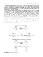
Types of Broaches.—A number of typical broaches and the operations for which they are
intended are shown by the diagrams, Fig. 1. Broach A produces a round-cornered, square
hole. Prior to broaching square holes, it is usually the practice to drill a round hole having a
diameter d somewhat larger than the width of the square. Hence, the sides are not com-
pletely finished, but this unfinished part is not objectionable in most cases. In fact, this
clearance space is an advantage during the broaching operation in that it serves as a chan-
nel for the broaching lubricant; moreover, the broach has less metal to remove. Broach B is
for finishing round holes. Broaching is superior to reaming for some classes of work,
because the broach will hold its size for a much longer period, thus insuring greater accu-
racy. Broaches C and D are for cutting single and double keyways, respectively. Broach C
is of rectangular section and, when in use, slides through a guiding bushing which is
inserted in the hole. Broach E is for forming four integral splines in a hub. The broach at F
is for producing hexagonal holes. Rectangular holes are finished by broach G. The teeth on
the sides of this broach are inclined in opposite directions, which has the following advan-
tages: The broach is stronger than it would be if the teeth were opposite and parallel to each
other; thin work cannot drop between the inclined teeth, as it tends to do when the teeth are
at right angles, because at least two teeth are always cutting; the inclination in opposite
directions neutralizes the lateral thrust. The teeth on the edges are staggered, the teeth on
one side being midway between the teeth on the other edge, as shown by the dotted line. A
double cut broach is shown at H. This type is for finishing, simultaneously, both sides f of
a slot, and for similar work. Broach I is the style used for forming the teeth in internal gears.
It is practically a series of gear-shaped cutters, the outside diameters of which gradually
increase toward the finishing end of the broach, Broach J is for round holes but differs from
style B in that it has a continuous helical cutting edge. Some prefer this form because it
gives a shearing cut. Broach K is for cutting a series of helical grooves in a hub or bushing.
In helical broaching, either the work or the broach is rotated to form the helical grooves as
the broach is pulled through.
In addition to the typical broaches shown in Fig. 1, many special designs are now in use
for performing more complex operations. Two surfaces on opposite sides of a casting or
forging are sometimes machined simultaneously by twin broaches and, in other cases,
three or four broaches are drawn through a part at the same time, for finishing as many
duplicate holes or surfaces. Notable developments have been made in the design of
broaches for external or “surface” broaching.
Burnishing Broach: This is a broach having teeth or projections which are rounded on
the top instead of being provided with a cutting edge, as in the ordinary type of broach. The
teeth are highly polished, the tool being used for broaching bearings and for operations on
Machinery's Handbook 27th Edition
Copyright 2004, Industrial Press, Inc., New York, NY
BROACHING 957
Table 1. Designing Data for Surface Broaches
Table 2. Broaching Pressure P for Use in Pitch Formula (2)
The minimum pitch shown by Formula (1) is based upon the receiving capacity of the
chip space. The minimum, however, should not be less than 0.2 inch unless a smaller pitch
is required for exceptionally short cuts to provide at least two teeth in contact simulta-
neously, with the part being broached. A reduction below 0.2 inch is seldom required in
surface broaching but it may be necessary in connection with internal broaching.
(1)
Whether the minimum pitch may be used or not depends upon the power of the available
machine. The factor F in the formula provides for the increase in volume as the material is
broached into chips. If a broach has adjustable inserts for the finishing teeth, the pitch of the
finishing teeth may be smaller than the pitch of the roughing teeth because of the smaller
depth d of the cut. The higher value of F for finishing teeth prevents the pitch from becom-
ing too small, so that the spirally curled chips will not be crowded into too small a space.
Material to be Broached
Depth of Cut per
Tooth, Inch
Face
Angle
or Rake,
Degrees
Clearance Angle,
Degrees
Roughing
a
a
The lower depth-of-cut values for roughing are recommended when work is not very rigid, the tol-
erance is small, a good finish is required, or length of cut is comparatively short.
Finishing Roughing Finishing
Steel, High Tensile Strength 0.0015–0.002 0.0005 10–12 1.5–3 0.5–1
Steel, Medium Tensile Strength 0.0025–0.005 0.0005 14–18 1.5–3 0.5–1
Cast Steel 0.0025–0.005 0.0005 10 1.53 0.5
Malleable Iron 0.0025–0.005 0.0005 7 1.5–3 0.5
Cast Iron, Soft 0.006 –0.010 0.0005 10–15 1.5–3 0.5
Cast Iron, Hard 0.003 –0.005 0.0005 5 1.5–3 0.5
Zinc Die Castings 0.005 –0.010 0.0010
12
b
b
In broaching these materials, smooth surfaces for tooth and chip spaces are especially recom-
mended.
52
Cast Bronze 0.010 –0.025 0.0005 8 0 0
Wrought Aluminum
Alloys 0.005 –0.010 0.0010
15
b
31
Cast Aluminum Alloys 0.005 –0.010 0.0010
12
b
31
Magnesium Die Castings 0.010 –0.015 0.0010
20
b
31
Material to be Broached
Depth d of Cut per Tooth, Inch
Pressure P,
Side-cutting
Broaches
0.024 0.010 0.004 0.002 0.001
Pressure P in Tons per Square Inch
Steel, High Ten. Strength …… …250 312 200 004″cut
Steel, Med. Ten. Strength ……158 185 243 143 006″ cut
Cast Steel ……128 158 … 115 006″ cut
Malleable Iron ……108 128 … 100 006″ cut
Cast Iron … 115 115 143 … 115 020″ cut
Cast Brass … 50 50 ……
Brass, Hot Pressed … 85 85 ……
Zinc Die Castings … 70 70 ……
Cast Bronze 35 35 …… …
Wrought Aluminum … 70 70 ……
Cast Aluminum … 85 85 ……
Magnesium Alloy 35 35 ………
Minimum pitch 3 LdF=
Machinery's Handbook 27th Edition
Copyright 2004, Industrial Press, Inc., New York, NY
BROACHING 959
Terms Commonly Used in Broach Design
Face Angle or Rake.—The face angle (see diagram) of broach teeth affects the chip flow
and varies considerably for different materials. While there are some variations in practice,
even for the same material, the angles given in the accompanying table are believed to rep-
resent commonly used values. Some broach designers increase the rake angle for finishing
teeth in order to improve the finish on the work.
Clearance Angle.—The clearance angle (see illustration) for roughing steel varies from
1.5 to 3 degrees and for finishing steel from 0.5 to 1 degree. Some recommend the same
clearance angles for cast iron and others, larger clearance angles varying from 2 to 4 or 5
degrees. Additional data will be found in Table 1.
Land Width.—The width of the land usually is about 0.25 × pitch. It varies, however,
from about one-fourth to one-third of the pitch. The land width is selected so as to obtain
the proper balance between tooth strength and chip space.
Depth of Broach Teeth.—The tooth depth as established experimentally and on the basis
of experience, usually varies from about 0.37 to 0.40 of the pitch. This depth is measured
radially from the cutting edge to the bottom of the tooth fillet.
Radius of Tooth Fillet.—The “gullet” or bottom of the chip space between the teeth
should have a rounded fillet to strengthen the broach, facilitate curling of the chips, and
safeguard against cracking in connection with the hardening operation. One rule is to make
the radius equal to one-fourth the pitch. Another is to make it equal 0.4 to 0.6 the tooth
depth. A third method preferred by some broach designers is to make the radius equal one-
third of the sum obtained by adding together the land width, one-half the tooth depth, and
one-fourth of the pitch.
Total Length of Broach.—After the depth of cut per tooth has been determined, the total
amount of material to be removed by a broach is divided by this decimal to ascertain the
number of cutting teeth required. This number of teeth multiplied by the pitch gives the
length of the active portion of the broach. By adding to this dimension the distance over
three or four straight teeth, the length of a pilot to be provided at the finishing end of the
broach, and the length of a shank which must project through the work and the faceplate of
the machine to the draw-head, the overall length of the broach is found. This calculated
length is often greater than the stroke of the machine, or greater than is practical for a
broach of the diameter required. In such cases, a set of broaches must be used.
Chip Breakers.—The teeth of broaches frequently have rounded chip-breaking grooves
located at intervals along the cutting edges. These grooves break up wide curling chips and
prevent them from clogging the chip spaces, thus reducing the cutting pressure and strain
on the broach. These chip-breaking grooves are on the roughing teeth only. They are stag-
gered and applied to both round and flat or surface broaches. The grooves are formed by a
round edged grinding wheel and usually vary in width from about
1
⁄
32
to
3
⁄
32
inch depending
upon the size of broach. The more ductile the material, the wider the chip breaker grooves
should be and the smaller the distance between them. Narrow slotting broaches may have
the right- and left-hand corners of alternate teeth beveled to obtain chip-breaking action.
Machinery's Handbook 27th Edition
Copyright 2004, Industrial Press, Inc., New York, NY
960 BROACHING
Shear Angle.—The teeth of surface broaches ordinarily are inclined so they are not at
right angles to the broaching movement. The object of this inclination is to obtain a shear-
ing cut which results in smoother cutting action and an improvement in surface finish. The
shearing cut also tends to eliminate troublesome vibration. Shear angles for surface
broaches are not suitable for broaching slots or any profiles that resist the outward move-
ment of the chips. When the teeth are inclined, the fixture should be designed to resist the
resulting thrusts unless it is practicable to incline the teeth of right- and left-hand sections
in opposite directions to neutralize the thrust. The shear angle usually varies from 10 to 25
degrees.
Types of Broaching Machines.—Broaching machines may be divided into horizontal
and vertical designs, and they may be classified further according to the method of opera-
tion, as, for example, whether a broach in a vertical machine is pulled up or pulled down in
forcing it through the work. Horizontal machines usually pull the broach through the work
in internal broaching but short rigid broaches may be pushed through. External surface
broaching is also done on some machines of horizontal design, but usually vertical
machines are employed for flat or other external broaching. Although parts usually are
broached by traversing the broach itself, some machines are designed to hold the broach or
broaches stationary during the actual broaching operation. This principle has been applied
both to internal and surface broaching.
Vertical Duplex Type: The vertical duplex type of surface broaching machine has two
slides or rams which move in opposite directions and operate alternately. While the broach
connected to one slide is moving downward on the cutting stroke, the other broach and
slide is returning to the starting position, and this returning time is utilized for reloading the
fixture on that side; consequently, the broaching operation is practically continuous. Each
ram or slide may be equipped to perform a separate operation on the same part when two
operations are required.
Pull-up Type: Vertical hydraulically operated machines which pull the broach or
broaches up through the work are used for internal broaching of holes of various shapes,
for broaching bushings, splined holes, small internal gears, etc. A typical machine of this
kind is so designed that all broach handling is done automatically.
Pull-down Type: The various movements in the operating cycle of a hydraulic pull-
down type of machine equipped with an automatic broach-handling slide, are the reverse
of the pull-up type. The broaches for a pull-down type of machine have shanks on each end,
there being an upper one for the broach-handling slide and a lower one for pulling through
the work.
Hydraulic Operation: Modern broaching machines, as a general rule, are operated
hydraulically rather than by mechanical means. Hydraulic operation is efficient, flexible in
the matter of speed adjustments, low in maintenance cost, and the “smooth” action
required for fine precision finishing may be obtained. The hydraulic pressures required,
which frequently are 800 to 1000 pounds per square inch, are obtained from a motor-driven
pump forming part of the machine. The cutting speeds of broaching machines frequently
are between 20 and 30 feet per minute, and the return speeds often are double the cutting
speed, or higher, to reduce the idle period.
Ball-Broaching.—Ball-broaching is a method of securing bushings, gears, or other com-
ponents without the need for keys, pins, or splines. A series of axial grooves, separated by
ridges, is formed in the bore of the workpiece by cold plastic deformation of the metal
when a tool, having a row of three rotating balls around its periphery, is pressed through the
parts. When the bushing is pressed into a broached bore, the ridges displace the softer
material of the bushing into the grooves—thus securing the assembly. The balls can be
made of high-carbon chromium steel or carbide, depending on the hardness of the compo-
nent.
Machinery's Handbook 27th Edition
Copyright 2004, Industrial Press, Inc., New York, NY
BROACHING 961
Broaching Difficulties.—The accompanying table has been compiled from information
supplied by the National Broach and Machine Co. and presents some of the common
broaching difficulties, their causes and means of correction.
Causes of Broaching Difficulties
Broaching
Difficulty Possible Causes
Stuck broach Insufficient machine capacity; dulled teeth; clogged chip gullets; failure of
power during cutting stroke.
To remove a stuck broach, workpiece and broach are removed from the
machine as a unit; never try to back out broach by reversing machine. If
broach does not loosen by tapping workpiece lightly and trying to slide it off
its starting end, mount workpiece and broach in a lathe and turn down work-
piece to the tool surface. Workpiece may be sawed longitudinally into sev-
eral sections in order to free the broach.
Check broach design, perhaps tooth relief (back off) angle is too small or
depth of cut per tooth is too great.
Galling and
pickup
Lack of homogeneity of material being broached—uneven hardness,
porosity; improper or insufficient coolant; poor broach design, mutilated
broach; dull broach; improperly sharpened broach; improperly designed or
outworn fixtures.
Good broach design will do away with possible chip build-up on tooth
faces and excessive heating. Grinding of teeth should be accurate so that the
correct gullet contour is maintained. Contour should be fair and smooth.
Broach breakage Overloading; broach dullness; improper sharpening; interrupted cutting
stroke; backing up broach with workpiece in fixture; allowing broach to pass
entirely through guide hole; ill fitting and/or sharp edged key; crooked
holes; untrue locating surface; excessive hardness of workpiece; insufficient
clearance angle; sharp corners on pull end of broach.
When grinding bevels on pull end of broach use wheel that is not too
pointed.
Chatter Too few teeth in cutting contact simultaneously; excessive hardness of
material being broached; loose or poorly constructed tooling; surging of ram
due to load variations.
Chatter can be alleviated by changing the broaching speed, by using shear
cutting teeth instead of right angle teeth, and by changing the coolant and the
face and relief angles of the teeth.
Drifting or
misalignment of
tool during
cutting stroke
Lack of proper alignment when broach is sharpened in grinding machine,
which may be caused by dirt in the female center of the broach; inadequate
support of broach during the cutting stroke, on a horizontal machine espe-
cially; body diameter too small; cutting resistance variable around I.D. of
hole due to lack of symmetry of surfaces to be cut; variations in hardness
around I.D. of hole; too few teeth in cutting contact.
Streaks in
broached surface
Lands too wide; presence of forging, casting or annealing scale; metal
pickup; presence of grinding burrs and grinding and cleaning abrasives.
Rings in the
broached hole
Due to surging resulting from uniform pitch of teeth; presence of sharpen-
ing burrs on broach; tooth clearance angle too large; locating face not
smooth or square; broach not supported for all cutting teeth passing through
the work. The use of differential tooth spacing or shear cutting teeth helps in
preventing surging. Sharpening burrs on a broach may be removed with a
wood block.
Machinery's Handbook 27th Edition
Copyright 2004, Industrial Press, Inc., New York, NY
962 FILES AND BURS
FILES AND BURS
Files
Definitions of File Terms.—The following file terms apply to hand files but not to rotary
files and burs.
Axis: Imaginary line extending the entire length of a file equidistant from faces and
edges.
Back: The convex side of a file having the same or similar cross-section as a half-round
file.
Bastard Cut: A grade of file coarseness between coarse and second cut of American pat-
tern files and rasps.
Blank: A file in any process of manufacture before being cut.
Blunt: A file whose cross-sectional dimensions from point to tang remain unchanged.
Coarse Cut: The coarsest of all American pattern file and rasp cuts.
Coarseness: Term describing the relative number of teeth per unit length, the coarsest
having the least number of file teeth per unit length; the smoothest, the most. American
pattern files and rasps have four degrees of coarseness: coarse, bastard, second and
smooth. Swiss pattern files usually have seven degrees of coarseness: 00, 0, 1, 2, 3, 4, 6
(from coarsest to smoothest). Curved tooth files have three degrees of coarseness: stan-
dard, fine and smooth.
Curved Cut: File teeth which are made in curved contour across the file blank.
Cut: Term used to describe file teeth with respect to their coarseness or their character
(single, double, rasp, curved, special).
Double Cut: A file tooth arrangement formed by two series of cuts, namely the overcut
followed, at an angle, by the upcut.
Edge: Surface joining faces of a file. May have teeth or be smooth.
Face: Widest cutting surface or surfaces that are used for filing.
Heel or Shoulder: That portion of a file that abuts the tang.
Hopped: A term used among file makers to represent a very wide skip or spacing
between file teeth.
Length: The distance from the heel to the point.
Overcut: The first series of teeth put on a double-cut file.
Point: The front end of a file; the end opposite the tang.
Rasp Cut: A file tooth arrangement of round-topped teeth, usually not connected, that
are formed individually by means of a narrow, punch-like tool.
Re-cut: A worn-out file which has been re-cut and re-hardened after annealing and
grinding off the old teeth.
Safe Edge: An edge of a file that is made smooth or uncut, so that it will not injure that
portion or surface of the workplace with which it may come in contact during filing.
Second Cut: A grade of file coarseness between bastard and smooth of American pattern
files and rasps.
Set: To blunt the sharp edges or corners of file blanks before and after the overcut is
made, in order to prevent weakness and breakage of the teeth along such edges or corners
when the file is put to use.
Shoulder or Heel: See Heel or Shoulder.
Single Cut: A file tooth arrangement where the file teeth are composed of single unbro-
ken rows of parallel teeth formed by a single series of cuts.
Smooth Cut: An American pattern file and rasp cut that is smoother than second cut.
Tang: The narrowed portion of a file which engages the handle.
Upcut: The series of teeth superimposed on the overcut, and at an angle to it, on a double-
cut file.
Machinery's Handbook 27th Edition
Copyright 2004, Industrial Press, Inc., New York, NY
FILES AND BURS 963
File Characteristics.—Files are classified according to their shape or cross-section and
according to the pitch or spacing of their teeth and the nature of the cut.
Cross-section and Outline: The cross-section may be quadrangular, circular, triangular,
or some special shape. The outline or contour may be tapered or blunt. In the former, the
point is more or less reduced in width and thickness by a gradually narrowing section that
extends for one-half to two-thirds of the length. In the latter the cross-section remains uni-
form from tang to point.
Cut: The character of the teeth is designated as single, double, rasp or curved. The single
cut file (or float as the coarser cuts are sometimes called) has a single series of parallel teeth
extending across the face of the file at an angle of from 45 to 85 degrees with the axis of the
file. This angle depends upon the form of the file and the nature of the work for which it is
intended. The single cut file is customarily used with a light pressure to produce a smooth
finish. The double cut file has a multiplicity of small pointed teeth inclining toward the
point of the file arranged in two series of diagonal rows that cross each other. For general
work, the angle of the first series of rows is from 40 to 45 degrees and of the second from 70
to 80 degrees. For double cut finishing files the first series has an angle of about 30 degrees
and the second, from 80 to 87 degrees. The second, or upcut, is almost always deeper than
the first or overcut. Double cut files are usually employed, under heavier pressure, for fast
metal removal and where a rougher finish is permissible. The rasp is formed by raising a
series of individual rounded teeth from the surface of the file blank with a sharp narrow,
punch-like cutting tool and is used with a relatively heavy pressure on soft substances for
fast removal of material. The curved tooth file has teeth that are in the form of parallel arcs
extending across the face of the file, the middle portion of each arc being closest to the
point of the file. The teeth are usually single cut and are relatively coarse. They may be
formed by steel displacement but are more commonly formed by milling.
With reference to coarseness of cut the terms coarse, bastard, second and smooth cuts are
used, the coarse or bastard files being used on the heavier classes of work and the second or
smooth cut files for the finishing or more exacting work. These degrees of coarseness are
only comparable when files of the same length are compared, as the number or teeth per
inch of length decreases as the length of the file increases. The number of teeth per inch
varies considerably for different sizes and shapes and for files of different makes. The
coarseness range for the curved tooth files is given as standard, fine and smooth. In the case
of Swiss pattern files, a series of numbers is used to designate coarseness instead of names;
Nos. 00, 0, 1, 2, 3, 4 and 6 being the most common with No. 00 the coarsest and No. 6 the
finest.
Classes of Files.—There are five main classes of files: mill or saw files; machinists' files;
curved tooth files; Swiss pattern files; and rasps. The first two classes are commonly
referred to as American pattern files.
Mill or Saw Files: These are used for sharpening mill or circular saws, large crosscut
saws; for lathe work; for draw filing; for filing brass and bronze; and for smooth filing gen-
erally. The number identifying the following files refers to the illustration in Fig. 1
1) Cantsaw files have an obtuse isosceles triangular section, a blunt outline, are single cut
and are used for sharpening saws having “M”-shaped teeth and teeth of less than 60-degree
angle; 2) Crosscut files have a narrow triangular section with short side rounded, a blunt
outline, are single cut and are used to sharpen crosscut saws. The rounded portion is used to
deepen the gullets of saw teeth and the sides are used to sharpen the teeth themselves. ;
3) Double ender fileshave a triangular section, are tapered from the middle to both ends,
are tangless are single cut and are used reversibly for sharpening saws; 4) The mill file
itself, is usually single cut, tapered in width, and often has two square cutting edges in addi-
tion to the cutting sides. Either or both edges may be rounded, however, for filing the gul-
Machinery's Handbook 27th Edition
Copyright 2004, Industrial Press, Inc., New York, NY
FILES AND BURS 965
flat, square, pillar, pillar narrow, half round and shell types. A special curved tooth file is
available with teeth divided by long angular serrations. The teeth are cut in an “off center”
arc. When moved across the work toward one edge of the file a fast cutting action is pro-
vided; when moved toward the other edge, a smoothing action; thus the file is made to
serve a dual purpose.
Swiss Pattern Files: These are used by tool and die makers, model makers and delicate
instrument parts finishers. They are made to closer tolerances than the conventional Amer-
ican pattern files although with similar cross-sections. The points of the Swiss pattern files
are smaller, the tapers are longer and they are available in much finer cuts. They are prima-
rily finishing tools for removing burrs left from previous finishing operations truing up
narrow grooves, notches and keyways, cleaning out corners and smoothing small parts.
For very fine work, round and square handled needle files, available in numerous cross-
sectional shapes in overall lengths from 4 to 7
3
⁄
4
inches, are used. Die sinkers use die sink-
ers files and die sinkers rifflers. The files, also made in many different cross-sectional
shapes, are 3
1
⁄
2
inches in length and are available in the cut Nos. 0, 1, 2, and 4. The rifflers
are from 5
1
⁄
2
to 6
3
⁄
4
inches long, have cutting surfaces on either end, and come in numerous
cross-sectional shapes in cut Nos. 0, 2, 3, 4 and 6. These rifflers are used by die makers for
getting into corners, crevices, holes and contours of intricate dies and molds. Used in the
same fashion as die sinkers rifflers, silversmiths rifflers, that have a much heavier cross-
section, are available in lengths from 6
7
⁄
8
to 8 inches and in cuts Nos. 0, 1, 2, and 3. Blunt
machine files in Cut Nos. 00, 0, and 2 for use in ordinary and bench filing machines are
available in many different cross-sectional shapes, in lengths from 3 to 8 inches.
Rasps: Rasps are employed for work on relatively soft substances such as wood, leather,
and lead where fast removal or material is required. They come in rectangular and half
round cross-sections, the latter with and without a sharp edge.
Special Purpose Files: Falling under one of the preceding five classes of files, but modi-
fied to meet the requirements of some particular function, are a number of special purpose
files. The long angle lathe file is used for filing work that is rotating in a lathe. The long
tooth angle provides a clean shear, eliminates drag or tear and is self-clearing. This file has
safe or uncut edges to protect shoulders of the work which are not to be filed. The foundry
file has especially sturdy teeth with heavy set edges for the snagging of castings—the
removing of fins, sprues, and other projections. The die casting file has extra strong teeth
on corners and edges as well as sides for working on die castings of magnesium, zinc, or
aluminum alloys. A special file for stainless steel is designed to stand up under the abrasive
action of stainless steel alloys. Aluminum rasps and files are designed to eliminate clog-
ging. A special tooth construction is used in one type of aluminum tile which breaks up the
filings, allows the file to clear itself and overcomes chatter. A brass file is designed so that
with a little pressure the sharp, high-cut teeth bite deep while with less pressure, their short
uncut angle produces a smoothing effect. The lead float has coarse, single cut teeth at
almost right angles to the file axis. These shear away the metal under ordinary pressure and
produce a smoothing effect under light pressure. The shear tooth file has a coarse single cut
with a long angle for soft metals or alloys, plastics, hard rubber and wood. Chain saw files
are designed to sharpen all types of chain saw teeth. These files come in round, rectangular,
square and diamond-shaped sections. The round and square sectioned files have either
double or single cut teeth, the rectangular files have single cut teeth and the diamond-
shaped files have double cut teeth.
Effectiveness of Rotary Files and Burs.—There it very little difference in the efficiency
of rotary files or burs when used in electric tools and when used in air tools, provided the
speeds have been reasonably well selected. Flexible-shaft and other machines used as a
source of power for these tools have a limited number of speeds which govern the revolu-
tions per minute at which the tools can be operated.
Machinery's Handbook 27th Edition
Copyright 2004, Industrial Press, Inc., New York, NY
966 FILES AND BURS
The carbide bur may be used on hard or soft materials with equally good results. The
principle difference in construction of the carbide bur is that its teeth or flutes are provided
with a negative rather than a radial rake. Carbide burs are relatively brittle, and must be
treated more carefully than ordinary burs. They should be kept cutting freely, in order to
prevent too much pressure, which might result in crumbling of the cutting epics.
At the same speeds, both high-speed steel and carbide burs remove approximately the
same amount of metal. However, when carbide burs are used at their most efficient speeds,
the rate of stock removal may be as much as four times that of ordinary burs. In certain
cases, speeds much higher than those shown in the table can be used. It has been demon-
strated that a carbide bur will last up to 100 times as long as a high-speed steel bur of corre-
sponding size and shape.
Approximate Speeds of Rotary Files and Burs
As recommended by the Nicholson File Company.
Steel Wool.—Steel wool is made by shaving thin layers of steel from wire. The wire is
pulled, by special machinery built for the purpose, past cutting tools or through cutting dies
which shave off chips from the outside. Steel wool consists of long, relatively strong, and
resilient steel shavings having sharp edges. This characteristic renders it an excellent abra-
sive. The fact that the cutting characteristics of steel wool vary with the size of the fiber,
which is readily controlled in manufacture, has adapted it to many applications.
Metals other than steel have been made into wool by the same processes as steel, and
when so manufactured have the same general characteristics. Thus wool has been made
from copper, lead, aluminum, bronze, brass, monel metal, and nickel. The wire from which
steel wool is made may be produced by either the Bessemer, or the basic or acid open-
hearth processes. It should contain from 0.10 to 0.20 per cent carbon; from 0.50 to 1.00 per
cent manganese; from 0.020 to 0.090 per cent sulphur; from 0.050 to 0.120 per cent phos-
phorus; and from 0.001 to 0.010 per cent silicon. When drawn on a standard tensile-
strength testing machine, a sample of the steel should show an ultimate strength of not less
than 120,000 pounds per square inch.
Steel Wool Grades
Tool
Diam.,
Inches
Medium Cut, High-Speed Steel Bur or File Carbide Bur
Mild Steel Cast Iron Bronze Aluminum Magnesium
Medium
Cut
Fine
Cut
Speed, Revolutions per Minute Any Material
1
⁄
8
4600 7000 15,000 20,000 30,000 45,000 30,000
1
⁄
4
3450 5250 11,250 15,000 22,500 30,000 20,000
3
⁄
8
2750 4200 9000 12,000 18,000 24,000 16,000
1
⁄
2
2300 3500 7500 10,000 15,000 20,000 13,350
5
⁄
8
2000 3100 6650 8900 13,350 18,000 12,000
3
⁄
4
1900 2900 6200 8300 12,400 16,000 10,650
7
⁄
8
1700 2600 5600 7500 11,250 14,500 9650
1 1600 2400 5150 6850 10,300 13,000 8650
1
1
⁄
8
1500 2300 4850 6500 9750 ……
1
1
⁄
4
1400 2100 4500 6000 9000 ……
Description Grade
Fiber Thickness
Description Grade
Fiber Thickness
Inch Millimeter Inch Millimeter
Super Fine 0000 0.001 0.025 Medium 1 0.0025 0.06
Extra Fine 000 0.0015 0.035 Medium Coarse 2 0.003 0.075
Very Fine 00 0.0018 0.04 Coarse 3 0.0035 0.09
Fine 0 0.002 0.05 Extra Coarse 4 0.004 0.10
Machinery's Handbook 27th Edition
Copyright 2004, Industrial Press, Inc., New York, NY
TOOL WEAR 967
TOOL WEAR AND SHARPENING
Metal cutting tools wear constantly when they are being used. A normal amount of wear
should not be a cause for concern until the size of the worn region has reached the point
where the tool should be replaced. Normal wear cannot be avoided and should be differen-
tiated from abnormal tool breakage or excessively fast wear. Tool breakage and an exces-
sive rate of wear indicate that the tool is not operating correctly and steps should be taken
to correct this situation.
There are several basic mechanisms that cause tool wear. It is generally understood that
tools wear as a result of abrasion which is caused by hard particles of work material plow-
ing over the surface of the tool. Wear is also caused by diffusion or alloying between the
work material and the tool material. In regions where the conditions of contact are favor-
able, the work material reacts with the tool material causing an attrition of the tool material.
The rate of this attrition is dependent upon the temperature in the region of contact and the
reactivity of the tool and the work materials with each other. Diffusion or alloying also
occurs where particles of the work material are welded to the surface of the tool. These
welded deposits are often quite visible in the form of a built-up edge, as particles or a layer
of work material inside a crater or as small mounds attached to the face of the tool. The dif-
fusion or alloying occurring between these deposits and the tool weakens the tool material
below the weld. Frequently these deposits are again rejoined to the chip by welding or they
are simply broken away by the force of collision with the passing chip. When this happens,
a small amount of the tool material may remain attached to the deposit and be plucked from
the surface of the tool, to be carried away with the chip. This mechanism can cause chips to
be broken from the cutting edge and the formation of small craters on the tool face called
pull-outs. It can also contribute to the enlargement of the larger crater that sometimes
forms behind the cutting edge. Among the other mechanisms that can cause tool wear are
severe thermal gradients and thermal shocks, which cause cracks to form near the cutting
edge, ultimately leading to tool failure. This condition can be caused by improper tool
grinding procedures, heavy interrupted cuts, or by the improper application of cutting flu-
ids when machining at high cutting speeds. Chemical reactions between the active constit-
uents in some cutting fluids sometimes accelerate the rate of tool wear. Oxidation of the
heated metal near the cutting edge also contributes to tool wear, particularly when fast cut-
ting speeds and high cutting temperatures are encountered. Breakage of the cutting edge
caused by overloading, heavy shock loads, or improper tool design is not normal wear and
should be corrected.
The wear mechanisms described bring about visible manifestations of wear on the tool
which should be understood so that the proper corrective measures can be taken, when
required. These visible signs of wear are described in the following paragraphs and the cor-
rective measures that might be required are given in the accompanying Tool Trouble-
Shooting Check List. The best procedure when trouble shooting is to try to correct only one
condition at a time. When a correction has been made it should be checked. After one con-
dition has been corrected, work can then start to correct the next condition.
Flank Wear: Tool wear occurring on the flank of the tool below the cutting edge is called
flank wear. Flank wear always takes place and cannot be avoided. It should not give rise to
concern unless the rate of flank wear is too fast or the flank wear land becomes too large in
size. The size of the flank wear can be measured as the distance between the top of the cut-
ting edge and the bottom of the flank wear land. In practice, a visual estimate is usually
made instead of a precise measurement, although in many instances flank wear is ignored
and the tool wear is “measured” by the loss of size on the part. The best measure of tool
wear, however, is flank wear. When it becomes too large, the rubbing action of the wear
land against the workpiece increases and the cutting edge must be replaced. Because con-
ditions vary, it is not possible to give an exact amount of flank wear at which the tool should
be replaced. Although there are many exceptions, as a rough estimate, high-speed steel
Machinery's Handbook 27th Edition
Copyright 2004, Industrial Press, Inc., New York, NY
968 TOOL SHARPENING
tools should be replaced when the width of the flank wear land reaches 0.005 to 0.010 inch
for finish turning and 0.030 to 0.060 inch for rough turning; and for cemented carbides
0.005 to 0.010 inch for finish turning and 0.020 to 0.040 inch for rough turning.
Under ideal conditions which, surprisingly, occur quite frequently, the width of the flank
wear land will be very uniform along its entire length. When the depth of cut is uneven,
such as when turning out-of-round stock, the bottom edge of the wear land may become
somewhat slanted, the wear land being wider toward the nose. A jagged-appearing wear
land usually is evidence of chipping at the cutting edge. Sometimes, only one or two sharp
depressions of the lower edge of the wear land will appear, to indicate that the cutting edge
has chipped above these depressions. A deep notch will sometimes occur at the “depth of
cut line,” or that part of the cutting opposite the original surface of the work. This can be
caused by a hard surface scale on the work, by a work-hardened surface layer on the work,
or when machining high-temperature alloys. Often the size of the wear land is enlarged at
the nose of the tool. This can be a sign of crater breakthrough near the nose or of chipping
in this region. Under certain conditions, when machining with carbides, it can be an indica-
tion of deformation of the cutting edge in the region of the nose.
When a sharp tool is first used, the initial amount of flank wear is quite large in relation to
the subsequent total amount. Under normal operating conditions, the width of the flank
wear land will increase at a uniform rate until it reaches a critical size after which the cut-
ting edge breaks down completely. This is called catastrophic failure and the cutting edge
should be replaced before this occurs. When cutting at slow speeds with high-speed steel
tools, there may be long periods when no increase in the flank wear can be observed. For a
given work material and tool material, the rate of flank wear is primarily dependent on the
cutting speed and then the feed rate.
Cratering: A deep crater will sometimes form on the face of the tool which is easily rec-
ognizable. The crater forms at a short distance behind the side cutting edge leaving a small
shelf between the cutting edge and the edge of the crater. This shelf is sometimes covered
with the built-up edge and at other times it is uncovered. Often the bottom of the crater is
obscured with work material that is welded to the tool in this region. Under normal operat-
ing conditions, the crater will gradually enlarge until it breaks through a part of the cutting
edge. Usually this occurs on the end cutting edge just behind the nose. When this takes
place, the flank wear at the nose increases rapidly and complete tool failure follows
shortly. Sometimes cratering cannot be avoided and a slow increase in the size of the crater
is considered normal. However, if the rate of crater growth is rapid, leading to a short tool
life, corrective measures must be taken.
Cutting Edge Chipping: Small chips are sometimes broken from the cutting edge which
accelerates tool wear but does not necessarily cause immediate tool failure. Chipping can
be recognized by the appearance of the cutting edge and the flank wear land. A sharp
depression in the lower edge of the wear land is a sign of chipping and if this edge of the
wear land has a jagged appearance it indicates that a large amount of chipping has taken
place. Often the vacancy or cleft in the cutting edge that results from chipping is filled up
with work material that is tightly welded in place. This occurs very rapidly when chipping
is caused by a built-up edge on the face of the tool. In this manner the damage to the cutting
edge is healed; however, the width of the wear land below the chip is usually increased and
the tool life is shortened.
Deformation: Deformation occurs on carbide cutting tools when taking a very heavy cut
using a slow cutting speed and a high feed rate. A large section of the cutting edge then
becomes very hot and the heavy cutting pressure compresses the nose of the cutting edge,
thereby lowering the face of the tool in the area of the nose. This reduces the relief under the
nose, increases the width of the wear land in this region, and shortens the tool life.
Surface Finish: The finish on the machined surface does not necessarily indicate poor
cutting tool performance unless there is a rapid deterioration. A good surface finish is,
Machinery's Handbook 27th Edition
Copyright 2004, Industrial Press, Inc., New York, NY
TOOL SHARPENING 969
however, sometimes a requirement. The principal cause of a poor surface finish is the
built-up edge which forms along the edge of the cutting tool. The elimination of the built-
up edge will always result in an improvement of the surface finish. The most effective way
to eliminate the built-up edge is to increase the cutting speed. When the cutting speed is
increased beyond a certain critical cutting speed, there will be a rather sudden and large
improvement in the surface finish. Cemented carbide tools can operate successfully at
higher cutting speeds, where the built-up edge does not occur and where a good surface fin-
ish is obtained. Whenever possible, cemented carbide tools should be operated at cutting
speeds where a good surface finish will result. There are times when such speeds are not
possible. Also, high-speed tools cannot be operated at the speed where the built-up edge
does not form. In these conditions the most effective method of obtaining a good surface
finish is to employ a cutting fluid that has active sulphur or chlorine additives.
Cutting tool materials that do not alloy readily with the work material are also effective in
obtaining an improved surface finish. Straight titanium carbide and diamond are the two
principal tool materials that fall into this category.
The presence of feed marks can mar an otherwise good surface finish and attention must
be paid to the feed rate and the nose radius of the tool if a good surface finish is desired.
Changes in the tool geometry can also be helpful. A small “flat,” or secondary cutting edge,
ground on the end cutting edge behind the nose will sometimes provide the desired surface
finish. When the tool is in operation, the flank wear should not be allowed to become too
large, particularly in the region of the nose where the finished surface is produced.
Sharpening Twist Drills.—Twist drills are cutting tools designed to perform concur-
rently several functions, such as penetrating directly into solid material, ejecting the
removed chips outside the cutting area, maintaining the essentially straight direction of the
advance movement and controlling the size of the drilled hole. The geometry needed for
these multiple functions is incorporated into the design of the twist drill in such a manner
that it can be retained even after repeated sharpening operations. Twist drills are resharp-
ened many times during their service life, with the practically complete restitution of their
original operational characteristics. However, in order to assure all the benefits which the
design of the twist drill is capable of providing, the surfaces generated in the sharpening
process must agree with the original form of the tool's operating surfaces, unless a change
of shape is required for use on a different work material.
The principal elements of the tool geometry which are essential for the adequate cutting
performance of twist drills are shown in Fig. 1. The generally used values for these dimen-
sions are the following:
Point angle: Commonly 118°, except for high strength steels, 118° to 135°; aluminum
alloys, 90° to 140°; and magnesium alloys, 70° to 118°.
Helix angle: Commonly 24° to 32°, except for magnesium and copper alloys, 10° to 30°.
Lip relief angle: Commonly 10° to 15°, except for high strength or tough steels, 7° to 12°.
The lower values of these angle ranges are used for drills of larger diameter, the higher
values for the smaller diameters. For drills of diameters less than
1
⁄
4
inch, the lip relief
angles are increased beyond the listed maximum values up to 24°. For soft and free
machining materials, 12° to 18° except for diameters less than
1
⁄
4
inch, 20° to 26°.
Relief Grinding of the Tool Flanks.—In sharpening twist drills the tool flanks contain-
ing the two cutting edges are ground. Each flank consists of a curved surface which pro-
vides the relief needed for the easy penetration and free cutting of the tool edges. In
grinding the flanks, Fig. 2, the drill is swung around the axis A of an imaginary cone while
resting in a support which holds the drill at one-half the point angle B with respect to the
face of the grinding wheel. Feed f for stock removal is in the direction of the drill axis. The
relief angle is usually measured at the periphery of the twist drill and is also specified by
that value. It is not a constant but should increase toward the center of the drill.
Machinery's Handbook 27th Edition
Copyright 2004, Industrial Press, Inc., New York, NY
TOOL SHARPENING 971
racy of the required tool geometry. Off-hand grinding may be used for the important web
thinning when a special machine is not available; however, such operation requires skill
and experience.
Improperly sharpened twist drills, e.g. those with unequal edge length or asymmetrical
point angle, will tend to produce holes with poor diameter and directional control.
For deep holes and also drilling into stainless steel, titanium alloys, high temperature
alloys, nickel alloys, very high strength materials and in some cases tool steels, split point
grinding, resulting in a “crankshaft” type drill point, is recommended. In this type of point-
ing, see Fig. 4, the chisel edge is entirely eliminated, extending the positive rake cutting
edges to the center of the drill, thereby greatly reducing the required thrust in drilling.
Points on modified-point drills must be restored after sharpening to maintain their
increased drilling efficiency.
Sharpening Carbide Tools.—Cemented carbide indexable inserts are usually not
resharpened but sometimes they require a special grind in order to form a contour on the
cutting edge to suit a special purpose. Brazed type carbide cutting tools are resharpened
after the cutting edge has become worn. On brazed carbide tools the cutting-edge wear
should not be allowed to become excessive before the tool is re-sharpened. One method of
determining when brazed carbide tools need resharpening is by periodic inspection of the
flank wear and the condition of the face. Another method is to determine the amount of
production which is normally obtained before excessive wear has taken place, or to deter-
mine the equivalent period of time. One disadvantage of this method is that slight varia-
tions in the work material will often cause the wear rate not to be uniform and the number
of parts machined before regrinding will not be the same each time. Usually, sharpening
should not require the removal of more than 0.005 to 0.010 inch of carbide.
General Procedure in Carbide Tool Grinding: The general procedure depends upon the
kind of grinding operation required. If the operation is to resharpen a dull tool, a diamond
wheel of 100 to 120 grain size is recommended although a finer wheel—up to 150 grain
size—is sometimes used to obtain a better finish. If the tool is new or is a “standard” design
and changes in shape are necessary, a 100-grit diamond wheel is recommended for rough-
ing and a finer grit diamond wheel can be used for finishing. Some shops prefer to rough
grind the carbide with a vitrified silicon carbide wheel, the finish grinding being done with
a diamond wheel. A final operation commonly designated as lapping may or may not be
employed for obtaining an extra-fine finish.
Wheel Speeds: The speed of silicon carbide wheels usually is about 5000 feet per minute.
The speeds of diamond wheels generally range from 5000 to 6000 feet per minute; yet
lower speeds (550 to 3000 fpm) can be effective.
Offhand Grinding: In grinding single-point tools (excepting chip breakers) the common
practice is to hold the tool by hand, press it against the wheel face and traverse it continu-
ously across the wheel face while the tool is supported on the machine rest or table which
is adjusted to the required angle. This is known as “offhand grinding” to distinguish it from
the machine grinding of cutters as in regular cutter grinding practice. The selection of
wheels adapted to carbide tool grinding is very important.
Silicon Carbide Wheels.—The green colored silicon carbide wheels generally are pre-
ferred to the dark gray or gray-black variety, although the latter are sometimes used.
Grain or Grit Sizes: For roughing, a grain size of 60 is very generally used. For finish
grinding with silicon carbide wheels, a finer grain size of 100 or 120 is common. A silicon
carbide wheel such as C60-I-7V may be used for grinding both the steel shank and carbide
tip. However, for under-cutting steel shanks up to the carbide tip, it may be advantageous
to use an aluminum oxide wheel suitable for grinding softer, carbon steel.
Grade: According to the standard system of marking, different grades from soft to hard
are indicated by letters from A to Z. For carbide tool grinding fairly soft grades such as G,
H, I, and J are used. The usual grades for roughing are I or J and for finishing H, I, and J. The
Machinery's Handbook 27th Edition
Copyright 2004, Industrial Press, Inc., New York, NY
972 TOOL SHARPENING
grade should be such that a sharp free-cutting wheel will be maintained without excessive
grinding pressure. Harder grades than those indicated tend to overheat and crack the car-
bide.
Structure: The common structure numbers for carbide tool grinding are 7 and 8. The
larger cup-wheels (10 to 14 inches) may be of the porous type and be designated as 12P.
The standard structure numbers range from 1 to 15 with progressively higher numbers
indicating less density and more open wheel structure.
Diamond Wheels.—Wheels with diamond-impregnated grinding faces are fast and cool
cutting and have a very low rate of wear. They are used extensively both for resharpening
and for finish grinding of carbide tools when preliminary roughing is required. Diamond
wheels are also adapted for sharpening multi-tooth cutters such as milling cutters, reamers,
etc., which are ground in a cutter grinding machine.
Resinoid bonded wheels are commonly used for grinding chip breakers, milling cutters,
reamers or other multi-tooth cutters. They are also applicable to precision grinding of car-
bide dies, gages, and various external, internal and surface grinding operations. Fast, cool
cutting action is characteristic of these wheels.
Metal bonded wheels are often used for offhand grinding of single-point tools especially
when durability or long life and resistance to grooving of the cutting face, are considered
more important than the rate of cutting. Vitrified bonded wheels are used both for roughing
of chipped or very dull tools and for ordinary resharpening and finishing. They provide
rigidity for precision grinding, a porous structure for fast cool cutting, sharp cutting action
and durability.
Diamond Wheel Grit Sizes.—For roughing with diamond wheels a grit size of 100 is the
most common both for offhand and machine grinding.
Grit sizes of 120 and 150 are frequently used in offhand grinding of single point tools
1) for resharpening; 2) for a combination roughing and finishing wheel; and 3) for chip-
breaker grinding.
Grit sizes of 220 or 240 are used for ordinary finish grinding all types of tools (offhand
and machine) and also for cylindrical, internal and surface finish grinding. Grits of 320 and
400 are used for “lapping” to obtain very fine finishes, and for hand hones. A grit of 500 is
for lapping to a mirror finish on such work as carbide gages and boring or other tools for
exceptionally fine finishes.
Diamond Wheel Grades.—Diamond wheels are made in several different grades to bet-
ter adapt them to different classes of work. The grades vary for different types and shapes
of wheels. Standard Norton grades are H, J, and L, for resinoid bonded wheels, grade N for
metal bonded wheels and grades J, L, N, and P, for vitrified wheels. Harder and softer
grades than standard may at times be used to advantage.
Diamond Concentration.—The relative amount (by carat weight) of diamond in the dia-
mond section of the wheel is known as the “diamond concentration.” Concentrations of
100 (high), 50 (medium) and 25 (low) ordinarily are supplied. A concentration of 50 repre-
sents one-half the diamond content of 100 (if the depth of the diamond is the same in each
case) and 25 equals one-fourth the content of 100 or one-half the content of 50 concentra-
tion.
100 Concentration: Generally interpreted to mean 72 carats of diamond/in.
3
of abrasive
section. (A 75 concentration indicates 54 carats/in.
3
.) Recommended (especially in grit
sizes up to about 220) for general machine grinding of carbides, and for grinding cutters
and chip breakers. Vitrified and metal bonded wheels usually have 100 concentration.
50 Concentration: In the finer grit sizes of 220, 240, 320, 400, and 500, a 50 concentra-
tion is recommended for offhand grinding with resinoid bonded cup-wheels.
Machinery's Handbook 27th Edition
Copyright 2004, Industrial Press, Inc., New York, NY
TOOL SHARPENING 973
25 Concentration: A low concentration of 25 is recommended for offhand grinding with
resinoid bonded cup-wheels with grit sizes of 100, 120 and 150.
Depth of Diamond Section: The radial depth of the diamond section usually varies from
1
⁄
16
to
1
⁄
4
inch. The depth varies somewhat according to the wheel size and type of bond.
Dry Versus Wet Grinding of Carbide Tools.—In using silicon carbide wheels, grinding
should be done either absolutely dry or with enough coolant to flood the wheel and tool.
Satisfactory results may be obtained either by the wet or dry method. However, dry grind-
ing is the most prevalent usually because, in wet grinding, operators tend to use an inade-
quate supply of coolant to obtain better visibility of the grinding operation and avoid
getting wet; hence checking or cracking in many cases is more likely to occur in wet grind-
ing than in dry grinding.
Wet Grinding with Silicon Carbide Wheels: One advantage commonly cited in connec-
tion with wet grinding is that an ample supply of coolant permits using wheels about one
grade harder than in dry grinding thus increasing the wheel life. Plenty of coolant also pre-
vents thermal stresses and the resulting cracks, and there is less tendency for the wheel to
load. A dust exhaust system also is unnecessary.
Wet Grinding with Diamond Wheels: In grinding with diamond wheels the general prac-
tice is to use a coolant to keep the wheel face clean and promote free cutting. The amount
of coolant may vary from a small stream to a coating applied to the wheel face by a felt pad.
Coolants for Carbide Tool Grinding.—In grinding either with silicon carbide or dia-
mond wheels a coolant that is used extensively consists of water plus a small amount either
of soluble oil, sal soda, or soda ash to prevent corrosion. One prominent manufacturer rec-
ommends for silicon carbide wheels about 1 ounce of soda ash per gallon of water and for
diamond wheels kerosene. The use of kerosene is quite general for diamond wheels and
usually it is applied to the wheel face by a felt pad. Another coolant recommended for dia-
mond wheels consists of 80 per cent water and 20 per cent soluble oil.
Peripheral Versus Flat Side Grinding.—In grinding single point carbide tools with sili-
con carbide wheels, the roughing preparatory to finishing with diamond wheels may be
done either by using the flat face of a cup-shaped wheel (side grinding) or the periphery of
a “straight” or disk-shaped wheel. Even where side grinding is preferred, the periphery of
a straight wheel may be used for heavy roughing as in grinding back chipped or broken
tools (see left-hand diagram). Reasons for preferring peripheral grinding include faster
cutting with less danger of localized heating and checking especially in grinding broad sur-
faces. The advantages usually claimed for side grinding are that proper rake or relief angles
are easier to obtain and the relief or land is ground flat. The diamond wheels used for tool
sharpening are designed for side grinding. (See right-hand diagram.)
Machinery's Handbook 27th Edition
Copyright 2004, Industrial Press, Inc., New York, NY
974 TOOL SHARPENING
Lapping Carbide Tools.—Carbide tools may be finished by lapping, especially if an
exceptionally fine finish is required on the work as, for example, tools used for precision
boring or turning non-ferrous metals. If the finishing is done by using a diamond wheel of
very fine grit (such as 240, 320, or 400), the operation is often called “lapping.” A second
lapping method is by means of a power-driven lapping disk charged with diamond dust,
Norbide powder, or silicon carbide finishing compound. A third method is by using a hand
lap or hone usually of 320 or 400 grit. In many plants the finishes obtained with carbide
tools meet requirements without a special lapping operation. In all cases any feather edge
which may be left on tools should be removed and it is good practice to bevel the edges of
roughing tools at 45 degrees to leave a chamfer 0.005 to 0.010 inch wide. This is done by
hand honing and the object is to prevent crumbling or flaking off at the edges when hard
scale or heavy chip pressure is encountered.
Hand Honing: The cutting edge of carbide tools, and tools made from other tool materi-
als, is sometimes hand honed before it is used in order to strengthen the cutting edge. When
interrupted cuts or heavy roughing cuts are to be taken, or when the grade of carbide is
slightly too hard, hand honing is beneficial because it will prevent chipping, or even possi-
bly, breakage of the cutting edge. Whenever chipping is encountered, hand honing the cut-
ting edge before use will be helpful. It is important, however, to hone the edge lightly and
only when necessary. Heavy honing will always cause a reduction in tool life. Normally,
removing 0.002 to 0.004 inch from the cutting edge is sufficient. When indexable inserts
are used, the use of pre-honed inserts is preferred to hand honing although sometimes an
additional amount of honing is required. Hand honing of carbide tools in between cuts is
sometimes done to defer grinding or to increase the life of a cutting edge on an indexable
insert. If correctly done, so as not to change the relief angle, this procedure is sometimes
helpful. If improperly done, it can result in a reduction in tool life.
Chip Breaker Grinding.—For this operation a straight diamond wheel is used on a uni-
versal tool and cutter grinder, a small surface grinder, or a special chipbreaker grinder. A
resinoid bonded wheel of the grade J or N commonly is used and the tool is held rigidly in
an adjustable holder or vise. The width of the diamond wheel usually varies from
1
⁄
8
to
1
⁄
4
inch. A vitrified bond may be used for wheels as thick as
1
⁄
4
inch, and a resinoid bond for
relatively narrow wheels.
Summary of Miscellaneous Points.—In grinding a single-point carbide tool, traverse it
across the wheel face continuously to avoid localized heating. This traverse movement
should be quite rapid in using silicon carbide wheels and comparatively slow with dia-
mond wheels. A hand traversing and feeding movement, whenever practicable, is gener-
ally recommended because of greater sensitivity. In grinding, maintain a constant,
moderate pressure. Manipulating the tool so as to keep the contact area with the wheel as
small as possible will reduce heating and increase the rate of stock removal. Never cool a
hot tool by dipping it in a liquid, as this may crack the tip. Wheel rotation should preferably
be against the cutting edge or from the front face toward the back. If the grinder is driven
by a reversing motor, opposite sides of a cup wheel can be used for grinding right-and left-
hand tools and with rotation against the cutting edge. If it is necessary to grind the top face
of a single-point tool, this should precede the grinding of the side and front relief, and top-
face grinding should be minimized to maintain the tip thickness. In machine grinding with
a diamond wheel, limit the feed per traverse to 0.001 inch for 100 to 120 grit; 0.0005 inch
for 150 to 240 grit; and 0.0002 inch for 320 grit and finer.
Machinery's Handbook 27th Edition
Copyright 2004, Industrial Press, Inc., New York, NY
JIGS AND FIXTURES 975
JIGS AND FIXTURES
Jig Bushings
Material for Jig Bushings.—Bushings are generally made of a good grade of tool steel to
ensure hardening at a fairly low temperature and to lessen the danger of fire cracking. They
can also be made from machine steel, which will answer all practical purposes, provided
the bushings are properly casehardened to a depth of about
1
⁄
16
inch. Sometimes, bushings
for guiding tools may be made of cast iron, but only when the cutting tool is of such a
design that no cutting edges come within the bushing itself. For example, bushings used
simply to support the smooth surface of a boring-bar or the shank of a reamer might, in
some instances, be made of cast iron, but hardened steel bushings should always be used
for guiding drills, reamers, taps, etc., when the cutting edges come in direct contact with
the guiding surfaces. If the outside diameter of the bushing is very large, as compared with
the diameter of the cutting tool, the cost of the bushing can sometimes be reduced by using
an outer cast-iron body and inserting a hardened tool steel bushing.
When tool steel bushings are made and hardened, it is recommended that A-2 steel be
used. The furnace should be set to 1750°F and the bushing placed in the furnace and held
there approximately 20 minutes after the furnace reaches temperature. Remove the bush-
ing and cool in still air. After the part cools to 100–150°F, immediately place in a temper-
ing furnace that has been heated to 300°F. Remove the bushing after one hour and cool in
still air. If an atmospherically controlled furnace is unavailable, the part should be wrapped
in stainless foil to prevent scaling and oxidation at the 1750°F temperature.
American National Standard Jig Bushings.—Specifications for the following types of
jig bushings are given in American National Standard B94.33-1974 (R1986). Head Type
Press Fit Wearing Bushings, Type H (Fig. 1 and Tables 1 and 3); Headless Type Press Fit
Wearing Bushings, Type P (Fig. 2 and Tables 1 and 3); Slip Type Renewable Wearing
Bushings, Type S (Fig. 3 and Tables 4 and 5); Fixed Type Renewable Wearing Bushings,
Type F (Fig. 4 and Tables 5 and 6); Headless Type Liner Bushings, Type L (Fig. 5 and
Table 7); and Head Type Liner Bushings, Type HL (Fig. 6 and Table 8). Specifications for
locking mechanisms are also given in Table 9.
Fig. 1. Head Type Press Fit-
Wearing Bushings — Type H
Fig. 2. Headless Type Press Fit
Wearing Bushings — Type P
Fig. 3. Slip Type Renewable
Wearing Bushings—Type S
Fig. 4. Fixed Type Renewable
Wearing Bushings — Type F
Fig. 5. Headless Type Liner
Bushings — Type L
Fig. 6. Head Type Liner
Bushings — Type HL
Machinery's Handbook 27th Edition
Copyright 2004, Industrial Press, Inc., New York, NY
JIGS AND FIXTURES 977
All dimensions are in inches.
See also Table 3 for additional specifications.
0.6406
to
0.7500
1.000 1.020 1.015 1.0018 1.0015
0.500
0.094 1.250 0.312
H-64-8
0.750 H-64-12
1.000 H-64-16
1.375 H-64-22
1.750 H-64-28
2.125 H-64-34
2.500 H-64-40
0.7656
to
1.0000
1.375 1.395 1.390 1.3772 1.3768
0.750
0.094 1.625 0.375
H-88-12
1.000 H-88-16
1.375 H-88-22
1.750 H-88-28
2.125 H-88-34
2.500 H-88-40
1.0156
to
1.3750
1.750 1.770 1.765 1.7523 1.7519
1.000
0.094 2.000 0.375
H-112-16
1.375 H-112-22
1.750 H-112-28
2.125 H-112-34
2.500 H-112-40
3.000 H-112-48
1.3906
to
1.7500
2.250 2.270 2.265 2.2525 2.2521
1.000
0.094 2.500 0.375
H-144-16
1.375 H-144-22
1.750 H-144-28
2.125 H-144-34
2.500 H-144-40
3.000 H-144-48
Table 2. American National Standard Headless Type Press Fit
Wearing Bushings — Type P ANSI B94.33-1974 (R1986)
Range of Hole
Sizes
A
Body Diameter B
Body
Length
C
Radius
D NumberNom
Unfinished Finished
MaxMinMaxMin
0.0135
up to and
including
0.0625
0.156 0.166 0.161 0.1578 0.1575
0.250
0.016
P-10-4
0.312 P-10-5
0.375 P-10-6
0.500 P-10-8
0.0630
to
0.0995
0.203 0.213 0.208 0.2046 0.2043
0.250
0.016
P-13-4
0.312 P-13-5
0.375 P-13-6
0.500 P-13-8
0.750 P-13-12
0.1015
to
0.1405
0.250 0.260 0.255 0.2516 0.2513
0.250
0.016
P-16-4
0.312 P-16-5
0.375 P-16-6
0.500 P-16-8
0.750 P-16-12
0.1406
to
0.1875
0.312 0.327 0.322 0.3141 0.3138
0.250
0.031
P-20-4
0.312 P-20-5
0.375 P-20-6
0.500 P-20-8
0.750 P-20-12
1.000 P-20-16
Table 1. (Continued) American National Standard Head Type Press Fit
Wearing Bushings — Type H ANSI B94.33-1974 (R1986)
Range
of Hole
Sizes
A
Body Diameter B
Body
Length
C
Radius
D
Head
Diam.
E
Max
Head
Thickness
F
Max NumberNom
Unfinished Finished
Max Min Max Min
Machinery's Handbook 27th Edition
Copyright 2004, Industrial Press, Inc., New York, NY
978 JIGS AND FIXTURES
All dimensions are in inches. See Table 3 for additional specifications.
0.1890
to
0.2500
0.406 0.421 0.416 0.4078 0.4075
0.250
0.031
P-26-4
0.312 P-26-5
0.375 P-26-6
0.500 P-26-8
0.750 P-26-12
1.000 P-26-16
1.375 P-26-22
1.750 P-26-28
0.2570
to
0.3125
0.500 0.520 0.515 0.5017 0.5014
0.312
0.047
P-32-5
0.375 P-32-6
0.500 P-32-8
0.750 P-32-12
1.000 P-32-16
1.375 P-32-22
1.750 P-32-28
0.3160
to
0.4219
0.625 0.645 0.640 0.6267 0.6264
0.312
0.047
P-40-5
0.375 P-40-6
0.500 P-40-8
0.750 P-40-12
1.000 P-40-16
1.375 P-40-22
1.750 P-40-28
2.125 P-40-34
0.4375 to 0.5000 0.750 0.770 0.765 0.7518 0.7515
0.500
0.062
P-48-8
0.750 P-48-12
1.000 P-48-16
1.375 P-48-22
1.750 P-48-28
2.125 P-48-34
0.5156
to
0.6250
0.875 0.895 0.890 0.8768 0.8765
0.500
0.062
P-56-8
0.750 P-56-12
1.000 P-56-16
1.375 P-56-22
1.750 P-56-28
2.125 P-56-34
2.500 P-56-40
0.6406
to
0.7500
1.000 1.020 1.015 1.0018 1.0015
0.500
0.062
P-64-8
0.750 P-64-12
1.000 P-64-16
1.375 P-64-22
1.750 P-64-28
2.125 P-64-34
2.500 P-64-40
0.7656
to
1.0000
1.375 1.395 1.390 1.3772 1.3768
0.750
0.094
P-88-12
1.000 P-88-16
1.375 P-88-22
1.750 P-88-28
2.125 P-88-34
2.500 P-88-40
1.0156
to
1.3750
1.750 1.770 1.765 1.7523 1.7519
1.000
0.094
P-112-16
1.375 P-112-22
1.750 P-112-28
2.125 P-112-34
2.500 P-112-40
3.000 P-112-48
1.3906
to
1.7500
2.250 2.270 2.265 2.2525 2.2521
1.000
0.094
P-144-16
1.375 P-144-22
1.750 P-144-28
2.125 P-144-34
2.500 P-144-40
3.000 P-144-48
Table 2. (Continued) American National Standard Headless Type Press Fit
Wearing Bushings — Type P ANSI B94.33-1974 (R1986)
Range of Hole
Sizes
A
Body Diameter B
Body
Length
C
Radius
D NumberNom
Unfinished Finished
MaxMinMaxMin
Machinery's Handbook 27th Edition
Copyright 2004, Industrial Press, Inc., New York, NY
JIG BUSHINGS 985
Jig Bushing Definitions.— Renewable Bushings: Renewable wearing bushings to guide
the tool are for use in liners which in turn are installed in the jig. They are used where the
bushing will wear out or become obsolete before the jig or where several bushings are to be
interchangeable in one hole. Renewable wearing bushings are divided into two classes,
“Fixed” and “Slip.” Fixed renewable bushings are installed in the liner with the intention
of leaving them in place until worn out. Slip renewable bushings are interchangeable in a
given size of liner and, to facilitate removal, they are usually made with a knurled head.
They are most frequently used where two or more operations requiring different inside
diameters are performed in a single jig, such as where drilling is followed by reaming, tap-
ping, spot facing, counterboring, or some other secondary operation.
Press Fit Bushings: Press fit wearing bushings to guide the tool are for installation
directly in the jig without the use of a liner and are employed principally where the bush-
ings are used for short production runs and will not require replacement. They are intended
also for short center distances.
Liner Bushings: Liner bushings are provided with and without heads and are perma-
nently installed in a jig to receive the renewable wearing bushings. They are sometimes
called master bushings.
Jig Plate Thickness.—The standard length of the press fit portion of jig bushings as estab-
lished are based on standardized uniform jig plate thicknesses of
5
⁄
16
,
3
⁄
8
,
1
⁄
2
,
3
⁄
4
, 1, 1
3
⁄
8
, 1
3
⁄
4
, 2
1
⁄
8
,
2
1
⁄
2
, and 3 inches.
Jig Bushing Designation System.—Inside Diameter: The inside diameter of the hole is
specified by a decimal dimension.
Type Bushing: The type of bushing is specified by a letter: S for Slip Renewable, F for
Fixed Renewable, L for Headless Liner, HL for Head Liner, P for Headless Press Fit, and
H for Head Press Fit.
Body Diameter: The body diameter is specified in multiples of 0.0156 inch. For exam-
ple, a 0.500-inch body diameter = 0.500/0.0156 = 32.
Body Length: The effective or body length is specified in multiples of 0.0625 inch. For
example, a 0.500-inch length = 0.500/0.0625 = 8.
Unfinished Bushings: All bushings with grinding stock on the body diameter are desig-
nated by the letter U following the number.
Example:A slip renewable bushing having a hole diameter of 0.5000 inch, a body diam-
eter of 0.750 inch, and a body length of 1.000 inch would be designated as .5000-S-48-16.
Jig Boring
Definition of Jig and Fixture.—The distinction between a jig and fixture is not easy to
define, but, as a general rule, it is as follows: A jig either holds or is held on the work, and,
at the same time, contains guides for the various cutting tools, whereas a fixture holds the
work while the cutting tools are in operation, but does not contain any special arrange-
ments for guiding the tools. A fixture, therefore, must be securely held or fixed to the
machine on which the operation is performed—hence the name. A fixture is sometimes
provided with a number of gages and stops, but not with bushings or other devices for guid-
ing and supporting the cutting tools.
Jig Borers.—Jig borers are used for precision hole-location work. For this reason, the
coordinate measuring systems on these machines are designed to provide longitudinal and
transverse movements that are accurate to 0.0001 in. One widely used method of obtaining
this accuracy utilizes ultraprecision lead screws. Another measuring system employs pre-
cision end measuring rods and a micrometer head that are placed in a trough which is par-
allel to the table movement. However, the purpose of all coordinate measuring systems
used is the same: to provide a method of aligning the spindle at the precise location where
a hole is to be produced. Since the work table of a jig borer moves in two directions, the
Machinery's Handbook 27th Edition
Copyright 2004, Industrial Press, Inc., New York, NY
986 JIG BORING
coordinate system of dimensioning is used, where dimensions are given from two perpen-
dicular reference axes, usually the sides of the workpiece, frequently its upper left-hand
corner. See Fig. 1C.
Jig-Boring Practice.—The four basic steps to follow to locate and machine a hole on a jig
borer are:
Align and Clamp the Workpiece: The first consideration in placing the workpiece on the
jig-borer table should be the relation of the coordinate measuring system of the jig borer to
the coordinate dimensions on the drawing. Therefore, the coordinate measuring system is
designed so that the readings of the coordinate measurements are direct when the table is
moved toward the left and when it is moved toward the column of the jig borer. The result
would be the same if the spindle were moved toward the right and away from the column,
with the workpiece situated in such a position that one reference axis is located at the left
and the other axis at the back, toward the column.
If the holes to be bored are to pass through the bottom of the workpiece, then the work-
piece must be placed on precision parallel bars. In order to prevent the force exerted by the
clamps from bending the workpiece the parallel bars are placed directly under the clamps,
which hold the workpiece on the table. The reference axes of the workpiece must also be
aligned with respect to the transverse and longitudinal table movements before it is firmly
clamped. This alignment can be done with a dial-test indicator held in the spindle of the jig
borer and bearing against the longitudinal reference edge. As the table is traversed in the
longitudinal direction, the workpiece is adjusted until the dial-test indicator readings are
the same for all positions.
Locate the Two Reference Axes of the Workpiece with Respect to the Spindle: The jig-
borer table is now moved to position the workpiece in a precise and known location from
where it can be moved again to the location of the holes to be machined. Since all the holes
are dimensioned from the two reference axes, the most convenient position to start from is
where the axis of the jig-borer spindle and the intersection of the two workpiece reference
axes are aligned. This is called the starting position, which is similar to a zero reference
position. When so positioned, the longitudinal and transverse measuring systems of the jig
borer are set to read zero. Occasionally, the reference axes are located outside the body of
the workpiece: a convenient edge or hole on the workpiece is picked up as the starting posi-
tion, and the dimensions from this point to the reference axes are set on the positioning
measuring system.
Locate the Hole: Precise coordinate table movements are used to position the workpiece
so that the spindle axis is located exactly where the hole is to be machined. When the mea-
suring system has been set to zero at the starting position, the coordinate readings at the
hole location will be the same as the coordinate dimensions of the hole center.
The movements to each hole must be made in one direction for both the transverse and
longitudinal directions, to eliminate the effect of any backlash in the lead screw. The usual
table movements are toward the left and toward the column.
The most convenient sequence on machines using micrometer dials as position indica-
tors (machines with lead screws) is to machine the hole closest to the starting position first
and then the next closest, and so on. On jig borers using end measuring rods, the opposite
sequence is followed: The farthest hole is machined first and then the next farthest, and so
on, since it is easier to remove end rods and replace them with shorter rods.
Drill and Bore Hole to Size: The sequence of operations used to produce a hole on a jig
borer is as follows: 1) a short, stiff drill, such as a center drill, that will not deflect when cut-
ting should be used to spot a hole when the work and the axis of the machine tool spindle
are located at the exact position where the hole is wanted; 2) the initial hole is made by a
twist drill; and 3) a single-point boring tool that is set to rotate about the axis of the
machine tool spindle is then used to generate a cut surface that is concentric to the axis of
rotation.
Machinery's Handbook 27th Edition
Copyright 2004, Industrial Press, Inc., New York, NY
JIG BORING 987
Heat will be generated by the drilling operation, so it is good practice to drill all the holes
first, and then allow the workpiece to cool before the holes are bored to size.
Transfer of Tolerances.—All of the dimensions that must be accurately held on preci-
sion machines and engine parts are usually given a tolerance. And when such dimensions
are changed from the conventional to the coordinate system of dimensioning, the toler-
ances must also be included. Because of their importance, the transfer of the tolerances
must be done with great care, keeping in mind that the sum of the tolerances of any pair of
dimensions in the coordinate system must not be larger than the tolerance of the dimension
that they replaced in the conventional system. An example is given in Fig. 1.
The first step in the procedure is to change the tolerances given in Fig. 1A to equal, bilat-
eral tolerances given in Fig. 1B. For example, the dimension 2.125
+.003
−.001
has a total tol-
erance of 0.004. The equal, bilateral tolerance would be plus or minus one-half of this
value, or ±.002. Then to keep the limiting dimensions the same, the basic dimension must
be changed to 2.126, in order to give the required values of 2.128 and 2.124. When chang-
ing to equal, bilateral tolerances, if the upper tolerance is decreased (as in this example),
the basic dimension must be increased by a like amount. The upper tolerance was
decreased by 0.003 − 0.002 = 0.001; therefore, the basic dimension was increased by 0.001
to 2.126. Conversely, if the upper tolerance is increased, the basic dimension is decreased.
The next step is to transfer the revised basic dimension to the coordinate dimensioning
system. To transfer the 2.126 dimension, the distance of the applicable holes from the left
reference axis must be determined. The first holes to the right are 0.8750 from the refer-
ence axis. The second hole is 2.126 to the right of the first holes. Therefore, the second hole
is 0.8750 + 2.126 = 3.0010 to the right of the reference axis. This value is then the coordi-
nate dimension for the second hole, while the 0.8750 value is the coordinate dimension of
the first two, vertically aligned holes. This procedure is followed for all the holes to find
their distances from the two reference axes. These values are given in Fig. 1C.
The final step is to transfer the tolerances. The 2.126 value in Fig. 1B has been replaced
by the 0.8750 and 3.0010 values in Fig. 1C. The 2.126 value has an available tolerance of
±0.002. Dividing this amount equally between the two replacement values gives 0.8750 ±
0.001 and 3.0010 ± 0.001. The sum of these tolerances is .002, and as required, does not
exceed the tolerance that was replaced. Next transfer the tolerance of the 0.502 dimension.
Divide the available tolerance, ±0.002, equally between the two replacement values to
yield 3.0010 ±0.001 and 3.5030 ±0.001. The sum of these two tolerances equals the
replaced tolerance, as required. However, the 1.125 value of the last hole to the right (coor-
dinate dimension 4.6280 in.) has a tolerance of only ±0.001. Therefore, the sum of the tol-
erances on the 3.5030 and 4.6280 values cannot be larger than 0.001. Dividing this
tolerance equally would give 3.5030 ± .0005 and 4.6280 ±0.0005. This new, smaller toler-
ance replaces the ± 0.001 tolerance on the 3.5030 value in order to satisfy all tolerance sum
requirements. This example shows how the tolerance of a coordinate value is affected by
more than one other dimensional requirement.
The following discussion will summarize the various tolerances listed in Fig. 1C. For the
0.8750 ± 0.0010 dimension, the ± 0.0010 tolerance together with the ± 0.0010 tolerance on
the 3.0010 dimension is required to maintain the ± 0.002 tolerance of the 2.126 dimension.
The ± .0005 tolerances on the 3.5030 and 4.2680 dimensions are required to maintain the ±
0.001 tolerance of the 1.125 dimension, at the same time as the sum of the ± .0005 tolerance
on the 3.5030 dimension and the ± 0.001 tolerance on the 3.0010 dimension does not
exceed the ± 0.002 tolerance on the replaced 0.503 dimension. The ± 0.0005 tolerances on
the 1.0000 and 2.0000 values maintain the ± 0.001 tolerance on the 1.0000 value given at
the right in Fig. 1A. The ± 0.0045 tolerance on the 3.0000 dimension together with the ±
0.0005 tolerance on the 1.0000 value maintains the ± .005 tolerance on the 2.0000 dimen-
sion of Fig. 1A. It should be noted that the 2.000 ± .005 dimension in Fig. 1A was replaced
by the 1.0000 and 3.0000 dimensions in Fig. 1C. Each of these values could have had a tol-
Machinery's Handbook 27th Edition
Copyright 2004, Industrial Press, Inc., New York, NY
JIG BORING 989
erance of ± 0.0025, except that the tolerance on the 1.0000 dimension on the left in Fig. 1A
is also bound by the ± 0.001 tolerance on the 1.0000 dimension on the right, thus the ±
0.0005 tolerance value is used. This procedure requires the tolerance on the 3.0000 value
to be increased to ± 0.0045.
Determining Hole Coordinates
On the following pages are given tables of the lengths of chords for spacing off the cir-
cumferences of circles. The object of these tables is to make possible the division of the
periphery into a number of equal parts without trials with the dividers. The first table,
Table 10, is calculated for circles having a diameter equal to 1. For circles of other diame-
ters, the length of chord given in the table should be multiplied by the diameter of the circle.
Table 10 may be used by toolmakers when setting “buttons” in circular formation. Assume
that it is required to divide the periphery of a circle of 20 inches diameter into thirty-two
equal parts. From the table the length of the chord is found to be 0.098017 inch, if the diam-
eter of the circle were 1 inch. With a diameter of 20 inches the length of the chord for one
division would be 20 × 0.098017 = 1.9603 inches. Another example in metric units: For a
100 millimeter diameter requiring 5 equal divisions, the length of the chord for one divi-
sion would be 100 × 0.587785 = 58.7785 millimeters.
Tables 11a and 11b starting on page 991 are additional tables for the spacing off of cir-
cles; the tables, in this case, being worked out for diameters from
1
⁄
16
inch to 14 inches. As
an example, assume that it is required to divide a circle having a diameter of 6
1
⁄
2
inches into
seven equal parts. Find first, in the column headed “6” and in line with 7 divisions, the
length of the chord for a 6-inch circle, which is 2.603 inches. Then find the length of the
chord for a
1
⁄
2
-inch diameter circle, 7 divisions, which is 0.217. The sum of these two val-
ues, 2.603 + 0.217 = 2.820 inches, is the length of the chord required for spacing off the
circumference of a 6
1
⁄
2
-inch circle into seven equal divisions.
As another example, assume that it is required to divide a circle having a diameter of 9
23
⁄
32
inches into 15 equal divisions. First find the length of the chord for a 9-inch circle, which is
1.871 inch. The length of the chord for a
23
⁄
32
-inch circle can easily be estimated from the
table by taking the value that is exactly between those given for
11
⁄
16
and
3
⁄
4
inch. The value
for
11
⁄
16
inch is 0.143, and for
3
⁄
4
inch, 0.156. For
23
⁄
32,
the value would be 0.150. Then, 1.871
+ 0.150 = 2.021 inches.
Hole Coordinate Dimension Factors for Jig Boring.—Tables of hole coordinate
dimension factors for use in jig boring are given in Tables 12 through 15 starting on
page 993. The coordinate axes shown in the figure accompanying each table are used to
reference the tool path; the values listed in each table are for the end points of the tool path.
In this machine coordinate system, a positive Y value indicates that the effective motion of
the tool with reference to the work is toward the front of the jig borer (the actual motion of
the jig borer table is toward the column). Similarly, a positive X value indicates that the
effective motion of the tool with respect to the work is toward the right (the actual motion
of the jig borer table is toward the left). When entering data into most computer-controlled
jig borers, current practice is to use the more familiar Cartesian coordinate axis system in
which the positive Y direction is “up” (i.e., pointing toward the column of the jig borer).
The computer will automatically change the signs of the entered Y values to the signs that
they would have in the machine coordinate system. Therefore, before applying the coordi-
nate dimension factors given in the tables, it is important to determine the coordinate sys-
tem to be used. If a Cartesian coordinate system is to be used for the tool path, then the sign
of the Y values in the tables must be changed, from positive to negative and from negative
to positive. For example, when programming for a three-hole type A circle using Cartesian
coordinates, the Y values from Table 14 would be y1 = + 0.50000, y2 = −0.25000, and y3 =
−0.25000.
Machinery's Handbook 27th Edition
Copyright 2004, Industrial Press, Inc., New York, NY
994 JIG BORING
17 Holes 18 Holes 19 Holes 20 Holes 21 Holes 22 Holes 23 Holes
x1 0.50000 x1 0.50000 x1 0.50000 x1 0.50000 x1 0.50000 x1 0.50000 x1 0.50000
y1 0.00000 y1 0.00000 y1 0.00000 y1 0.00000 y1 0.00000 y1 0.00000 y1 0.00000
x2 0.31938 x2 0.32899 x2 0.33765 x2 0.34549 x2 0.35262 x2 0.35913 x2 0.36510
y2 0.03376 y2 0.03015 y2 0.02709 y2 0.02447 y2 0.02221 y2 0.02025 y2 0.01854
x3 0.16315 x3 0.17861 x3 0.19289 x3 0.20611 x3 0.21834 x3 0.22968 x3 0.24021
y3 0.13050 y3 0.11698 y3 0.10543 y3 0.09549 y3 0.08688 y3 0.07937 y3 0.07279
x4 0.05242 x4 0.06699 x4 0.08142 x4 0.09549 x4 0.10908 x4 0.12213 x4 0.13458
y4 0.27713 y4
0.25000 y4 0.22653 y4 0.20611 y4 0.18826 y4 0.17257 y4 0.15872
x5 0.00213 x5 0.00760 x5 0.01530 x5 0.02447 x5 0.03456 x5 0.04518 x5 0.05606
y5 0.45387 y5 0.41318 y5 0.37726 y5 0.34549 y5 0.31733 y5 0.29229 y5 0.26997
x6 0.01909 x6 0.00760 x6 0.00171 x6 0.00000 x6 0.00140 x6 0.00509 x6 0.01046
y6 0.63683 y6 0.58682 y6 0.54129 y6 0.50000 y6 0.46263 y6 0.42884 y6 0.39827
x7 0.10099 x7 0.06699 x7 0.04211 x7 0.02447 x7 0.01254 x7 0.00509 x7 0.00117
y7 0.80132 y7 0.75000 y7 0.70085 y7 0.65451 y7 0.61126 y7 0.57116 y7 0.53412
x8 0.23678 x8 0.17861 x8 0.13214 x8
0.09549 x8 0.06699 x8 0.04518 x8 0.02887
y8 0.92511 y8 0.88302 y8 0.83864 y8 0.79389 y8 0.75000 y8 0.70771 y8 0.66744
x9 0.40813 x9 0.32899 x9 0.26203 x9 0.20611 x9 0.15991 x9 0.12213 x9 0.09152
y9 0.99149 y9 0.96985 y9 0.93974 y9 0.90451 y9 0.86653 y9 0.82743 y9 0.78834
x10 0.59187 x10 0.50000 x10 0.41770 x10 0.34549 x10 0.28306 x10 0.22968 x10 0.18446
y10 0.99149 y10 1.00000 y10 0.99318 y10 0.97553 y10 0.95048 y10 0.92063 y10 0.88786
x11 0.76322 x11 0.67101 x11 0.58230 x11 0.50000 x11 0.42548 x11 0.35913 x11 0.30080
y11 0.92511 y11 0.96985 y11 0.99318 y11 1.00000 y11
0.99442 y11 0.97975 y11 0.95861
x12 0.89901 x12 0.82139 x12 0.73797 x12 0.65451 x12 0.57452 x12 0.50000 x12 0.43192
y12 0.80132 y12 0.88302 y12 0.93974 y12 0.97553 y12 0.99442 y12 1.00000 y12 0.99534
x13 0.98091 x13 0.93301 x13 0.86786 x13 0.79389 x13 0.71694 x13 0.64087 x13 0.56808
y13 0.63683 y13 0.75000 y13 0.83864 y13 0.90451 y13 0.95048 y13 0.97975 y13 0.99534
x14 0.99787 x14 0.99240 x14 0.95789 x14 0.90451 x14 0.84009 x14 0.77032 x14 0.69920
y14 0.45387 y14 0.58682 y14 0.70085 y14 0.79389 y14 0.86653 y14 0.92063 y14 0.95861
x15 0.94758 x15 0.99240 x15 0.99829 x15 0.97553 x15 0.93301 x15 0.87787 x15
0.81554
y15 0.27713 y15 0.41318 y15 0.54129 y15 0.65451 y15 0.75000 y15 0.82743 y15 0.88786
x16 0.83685 x16 0.93301 x16 0.98470 x16 1.00000 x16 0.98746 x16 0.95482 x16 0.90848
y16 0.13050 y16 0.25000 y16 0.37726 y16 0.50000 y16 0.61126 y16 0.70771 y16 0.78834
x17 0.68062 x17 0.82139 x17 0.91858 x17 0.97553 x17 0.99860 x17 0.99491 x17 0.97113
y17 0.03376 y17 0.11698 y17 0.22658 y17 0.34549 y17 0.46263 y17 0.57116 y17 0.66744
x18 0.67101 x18 0.80711 x18 0.90451 x18 0.96544 x18 0.99491 x18 0.99883
y18 0.03015 y18 0.10543 y18 0.20611 y18 0.31733 y18 0.42884 y18 0.53412
x19 0.66235 x19 0.79389 x19
0.89092 x19 0.95482 x19 0.98954
y19 0.02709 y19 0.09549 y19 0.18826 y19 0.29229 y19 0.39827
x20 0.65451 x20 0.78166 x20 0.87787 x20 0.94394
y20 0.02447 y20 0.08688 y20 0.17257 y20 0.26997
x21 0.64738 x21 0.77032 x21 0.86542
y21 0.02221 y21 0.07937 y21 0.15872
x22 0.64087 x22 0.75979
y22 0.02025 y22 0.07279
x23 0.63490
y23 0.01854
24Holes 25 Holes 26 Holes 27 Holes 28 Holes
x1 0.50000 x1 0.50000 x1 0.50000 x1 0.50000 x1 0.50000
y1 0.00000 y1 0.00000 y1 0.00000 y1 0.00000 y1 0.00000
x2 0.37059 x2 0.37566 x2 0.38034 x2 0.38469 x2 0.38874
y2 0.01704 y2 0.01571 y2 0.01453 y2 0.01348 y2 0.01254
x3 0.25000 x3 0.25912
x3
0.26764 x3 0.27560 x3 0.28306
Table 12. (Continued) Hole Coordinate Dimension Factors for Jig Boring —
Type “A” Hole Circles (English or Metric Units)
The diagram shows a type “A” circle for a 5-hole circle. Coordinates x,
y are given in the table for hole circles of from 3 to 28 holes. Dimensions
are for holes numbered in a counterclockwise direction (as shown).
Dimensions given are based upon a hole circle of unit diameter. For a hole
circle of, say, 3-inch or 3-centimeter diameter, multiply table values by 3.
Machinery's Handbook 27th Edition
Copyright 2004, Industrial Press, Inc., New York, NY