Machinery''''s Handbook 27th Episode 2 Part 7 doc
Bạn đang xem bản rút gọn của tài liệu. Xem và tải ngay bản đầy đủ của tài liệu tại đây (614.44 KB, 58 trang )
NUMERICAL CONTROL 1275
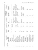
Table 2. G-Code Addresses
Code Description Code Description
G00
ab
*
Rapid traverse, point to point
(M,L)
G34
ab
*
Thread cutting, increasing
lead (L)
G01
abc
Linear interpolation (M,L) G35
abc
Thread cutting, decreasing lead (L)
G02
abc
Circular interpolation —
clockwise movement (M,L)
G36-G39
ab
Permanently unassigned
G36
c
Used for automatic
acceleration and deceleration
when the blocks are
short (M,L)
G03
abc
Circular interpolation—counter-
clockwise movement (M,L)
G04
ab
Dwell—a programmed time
delay (M,L)
G37, G37.1,
G37.2, G37.3
Used for tool gaging (M,L)
G05
ab
Unassigned G37.4
G06
abc
Parabolic interpolation (M,L) G38 Used for probing to measure the diame-
ter and center of a hole (M)
G07
c
Used for programming with
cylindrical diameter values (L)
G38.1 Used with a probe to measure
the parallelness of a part with
respect to an axis (M)
G08
ab
Programmed acceleration
(M,L).
d
Also for lathe
programming with cylindrical
diameter values
G39, G39.1 Generates a nonprogrammed
block to improve cycle time and
corner cutting quality when used
with cutter compensation (M)
G09
ab
Programmed deceleration
(M,L).
d
Used to stop the axis
movement at a precise location
(M,L)
G39 Tool tip radius compensation used
with linear generated block (L)
G10–G12
ab
Unassigned.
d
Sometimes used
for machine lock and unlock
devices
G39.1 Tool tip radius compensation used
used with circular generated block (L)
G13–G16
ac
Axis selection (M,L) G40
abc
Cancel cutter compensation/
offset (M)
G13–G16
b
Unassigned G41
abc
Cutter compensation, left (M)
G13 Used for computing lines and
circle intersections (M,L)
G42
abc
Cutter compensation, right (M)
G14, G14.1
c
Used for scaling (M,L) G43
abc
Cutter offset, inside corner (M,L)
G15–G16
c
Polar coordinate programming
(M)
G44
abc
Cutter offset, outside corner
(M,L)
G15, G16.1
c
Cylindrical interpolation—C
axis (L)
G45–G49
ab
Unassigned
G16.2
c
End face milling—C axis (L) G50–G59
a
Reserved for adaptive control
(M,L)
G17–G19
abc
X-Y, X-Z, Y-Z plane
selection, respectively (M,L)
G50
bb
Unassigned
G20 Unassigned G50.1
c
Cancel mirror image (M,L)
G22–G32
ab
Unassigned G51.1
c
Program mirror image (M,L)
G22–G23
c
Defines safety zones in which
the machine axis may not enter
(M,L)
G52
b
Unassigned
G22.1,
G233.1
c
Defines safety zones in which
the cutting tool may not exit
(M,L)
G52 Used to offset the axes with
respect to the coordinate zero
point (see G92) (M,L)
G24
c
Single-pass rough-facing cycle
(L)
G53
bc
Datum shift cancel
G27–G29 Used for automatically moving
to and returning from home
position (M,L)
G53
c
Call for motion in the machine
coordinate system (M,L)
G54–G59
bc
Datum shifts (M,L)
G30 Return to an alternate home
position (M,L)
G54–G59.3
c
Allows for presetting of work
coordinate systems (M,L)
G31, G31.1,
G31.2, G31.3,
G31.4
External skip function, moves
an axis on a linear path until
an external signal aborts the
move (M,L)
G60–G62
abc
Unassigned
G33
abc
Thread cutting, constant lead (L)
Machinery's Handbook 27th Edition
Copyright 2004, Industrial Press, Inc., New York, NY
1276 NUMERICAL CONTROL
G61
c
Modal equivalent of G09 except
that rapid moves are not taken
to a complete stop before the
next motion block is executed
(M,L)
G80
abc
Cancel fixed cycles
G81
abc
Drill cycle, no dwell and rapid out
(M,L)
G62
c
Automatic corner override,
reduces the feed rate on an
inside corner cut (M,L)
G82
abc
Drill cycle, dwell and rapid out
(M,L)
G63
a
Unassigned G83
abc
Deep hole peck drilling cycle
(M,L)
G63
bc
Tapping mode (M,L) G84
abc
Right-hand tapping cycle (M,L)
G64–G69
abc
Unassigned G84.1
c
Left-hand tapping cycle (M,L)
G64
c
Cutting mode, usually set by
the system installer (M,L)
G85
abc
Boring cycle, no dwell, feed out
(M,L)
G65
c
Calls for a parametric macro
(M,L)
G86
abc
Boring cycle, spindle stop,
rapid out (M,L)
G66
c
Calls for a parametric macro.
Applies to motion blocks only
(M,L)
G87
abc
Boring cycle, manual retraction
(M,L)
G88
abc
Boring cycle, spindle stop, manual
retraction (M,L)
G66.1
c
Same as G66 but applies to
all blocks (M,L)
G88.1 Pocket milling (rectangular and
circular), roughing cycle (M)
G67
c
Stop the modal parametric
macro (see G65, G66, G66.1)
(M,L)
G88.2 Pocket milling (rectangular and
circular), finish cycle (M)
G68
c
Rotates the coordinate system
(i.e., the axes) (M)
G88.3 Post milling, roughs out
material around a specified area
(M)
G69
c
Cancel axes rotation (M) G88.4 Post milling, finish cuts material
around a post (M)
G70
abc
Inch programming (M,L) G88.5 Hemisphere milling, roughing
cycle (M)
G71
abc
Metric programming (M,L)
G72
ac
Circular interpolation CW
(three-dimensional) (M)
G88.6 Hemisphere milling, finishing
cycle (M)
G72
b
Unassigned
G72
c
Used to perform the finish cut
on a turned part along the
Z-axis after the roughing cuts
initiated under G73, G74, or
G75 codes (L)
G89
abc
Boring cycle, dwell and feed out
(M,L)
G89.1 Irregular pocket milling,
roughing cycle (M)
G73
b
Unassigned
G73
c
Deep hole peck drilling cycle
(M); OD and ID roughing
cycle, running parallel to the
Z-axis (L)
G89.2 Irregular pocket milling,
finishing cycle (M)
G74
ac
Cancel multiquadrant circular
interpolation (M,L)
G90
abc
Absolute dimension input (M,L)
G74
bc
Move to home position (M,L) G91
abc
Incremental dimension input
(M,L)
G74
c
Left-hand tapping cycle (M) G92
abc
Preload registers, used to shift
the coordinate axes relative to
the current tool position (M,L)
G74 Rough facing cycle (L) G93
abc
Inverse time feed rate
(velocity/distance) (M,L)
G75
ac
Multiquadrant circular
interpolation (M,L)
G94
c
Feed rate in inches or millimeters
per minute (ipm or mpm) (M,L)
G75
b
Unassigned G95
abc
Feed rate given directly in inches or
millimeters per revolution (ipr
or mpr) (M,L)
G75 Roughing routine for castings or
forgings (L)
G76–G79
ab
Unassigned G96
abc
Maintains a constant surface speed,
feet (meters) per minute (L)
G97
abc
Spindle speed programmed
in rpm (M,L)
G98–99
ab
Unassigned
Table 2. (Continued) G-Code Addresses
Code Description Code Description
Machinery's Handbook 27th Edition
Copyright 2004, Industrial Press, Inc., New York, NY
NUMERICAL CONTROL 1277
Symbols following a description: (M) indicates that the code applies to a mill or machining center;
(L) indicates that the code applies to turning machines; (M,L) indicates that the code applies to both
milling and turning machines.
Codes that appear more than once in the table are codes that are in common use, but are not defined
by the Standard or are used in a manner that is different than that designated by the Standard (e.g., see
G61).
Most systems that support the RS-274-D Standard codes do not use all the codes avail-
able in the Standard. Unassigned G-words in the Standard are often used by builders of
machine tool control systems for a variety of special purposes, sometimes leading to con-
fusion as to the meanings of unassigned codes. Even more confusing, some builders of sys-
tems and machine tools use the less popular standardized codes for other than the meaning
listed in the Standard. For these reasons, machine code written specifically for one
machine/controller will not necessarily work correctly on another machine controller
without modification.
Dimension words contain numerical data that indicate either a distance or a position. The
dimension units are selected by using G70 (inch programming) or G71 (metric program-
ming) code. G71 is canceled by a G70 command, by miscellaneous functions M02 (end of
program), or by M30 (end of data). The dimension words immediately follow the G-word
in a block and on multiaxis machines should be placed in the following order: X, Y, Z, U,
V, W, P, Q, R, A, B, C, D, and E.
Absolute programming (G90) is a method of defining the coordinate locations of points
to which the cutter (or workpiece) is to move based on the fixed machine zero point. In Fig.
1, the X − Y coordinates of P1 are X = 1.0, Y = 0.5 and the coordinates of P2 are X = 2.0, Y =
1.1. To indicate the movement of the cutter from one point to another when using the abso-
lute coordinate system, only the coordinates of the destination point P2 are needed.
Incremental programming (G91) is a method of identifying the coordinates of a particu-
lar location in terms of the distance of the new location from the current location. In the
example shown in Fig. 2, a move from P1 to P2 is written as X + 1.0, Y + 0.6. If there is no
movement along the Z-axis, Z is zero and normally is not noted. An X − Y incremental
move from P2 to P3 in Fig. 2 is written as X + 1.0, Y − 0.7.
Most CNC systems offer both absolute and incremental part programming. The choice is
handled by G-code G90 for absolute programming and G91 for incremental programming.
G90 and G91 are both modal, so they remain in effect until canceled.
a
Adheres to ANSI/EIA RS-274-D;
b
Adheres to ISO 6983/1,2,3 Standards; where both symbols appear together, the ANSI/EIA and
ISO standard codes are comparable;
c
This code is modal. All codes that are not identified as modal are nonmodal, when used according
to the corresponding definition.
d
Indicates a use of the code that does not conform with the Standard.
Fig. 1. Fig. 2.
Machinery's Handbook 27th Edition
Copyright 2004, Industrial Press, Inc., New York, NY
1278 NUMERICAL CONTROL
The G92 word is used to preload the registers in the control system with desired values. A
common example is the loading of the axis-position registers in the control system for a
lathe. Fig. 3 shows a typical home position of the tool tip with respect to the zero point on
the machine. The tool tip here is registered as being 15.0000 inches in the Z-direction and
4.5000 inches in the X-direction from machine zero. No movement of the tool is required.
Although it will vary with different control system manufacturers, the block to accomplish
the registration shown in Fig. 3 will be approximately:
N0050 G92 X4.5 Z15.0
Miscellaneous Functions (M-Words).—Miscellaneous functions, or M-codes, also
referred to as auxiliary functions, constitute on-off type commands. M functions are used
to control actions such as starting and stopping of motors, turning coolant on and off,
changing tools, and clamping and unclamping parts. M functions are made up of the letter
M followed by a two-digit code. Table 3 lists the standardized M-codes, however, the func-
tions available will vary from one control system to another. Most systems provide fewer
M functions than the complete list and may use some of the unassigned codes to provide
additional functions that are not covered by the Standard. If an M-code is used in a block, it
follows the T-word and is normally the last word in the block.
Table 3. Miscellaneous Function Words from ANSI/EIA RS-274-D
Code Description
M00 Automatically stops the machine. The operator must push a button to continue
with the remainder of the program.
M01 An optional stop acted upon only when the operator has previously signaled for
this command by pushing a button. The machine will automatically stop when the
control system senses the M01 code.
M02 This end-of-program code stops the machine when all commands in the block are
completed. May include rewinding of tape.
M03 Start spindle rotation in a clockwise direction—looking out from the spindle face.
M04 Start spindle rotation in a counterclockwise direction—looking out from the spin-
dle face.
M05 Stop the spindle in a normal and efficient manner.
M06 Command to change a tool (or tools) manually or automatically. Does not cover
tool selection, as is possible with the T-words.
M07 to M08 M07 (coolant 2) and M08 (coolant 1) are codes to turn on coolant. M07 may con-
trol flood coolant and M08 mist coolant.
M09 Shuts off the coolant.
M10 to M11 M10 applies to automatic clamping of the machine slides, workpiece, fixture spin-
dle, etc. M11 is an unclamping code.
M12 An inhibiting code used to synchronize multiple sets of axes, such as a four-axis
lathe having two independently operated heads (turrets).
M13 Starts CW spindle motion and coolant on in the same command.
M14 Starts CCW spindle motion and coolant on in the same command.
M15 to M16 Rapid traverse of feed motion in either the +(M15) or −(M16) direction.
M17 to M18 Unassigned.
M19 Oriented spindle stop. Causes the spindle to stop at a predetermined angular posi-
tion.
M20 to M29 Permanently unassigned.
M30 An end-of-tape code similar to M02, but M30 will also rewind the tape; also may
switch automatically to a second tape reader.
M31 A command known as interlock bypass for temporarily circumventing a
normally provided interlock.
Machinery's Handbook 27th Edition
Copyright 2004, Industrial Press, Inc., New York, NY
1280 NUMERICAL CONTROL
per tooth to feed per revolution, multiply the feed rate per tooth by the number of cutter
teeth: feed/revolution = feed/tooth × number of teeth.
For certain types of cuts, some systems require an inverse-time feed command that is the
reciprocal of the time in minutes required to complete the block of instructions. The feed
command is indicated by a G93 code followed by an F-word value found by dividing the
feed rate, in inches (millimeters) or degrees per minute, by the distance moved in the block:
feed command = feed rate/distance = (distance/time)/distance = 1/time.
Feed-rate override refers to a control, usually a rotary dial on the control system panel,
that allows the programmer or operator to override the programmed feed rate. Feed-rate
override does not change the program; permanent changes can only be made by modifying
the program. The range of override typically extends from 0 to 150 per cent of the pro-
grammed feed rate on CNC machines; older hardwired systems are more restrictive and
most cannot be set to exceed 100 per cent of the preset rate.
Spindle Function (S-Word).—An S-word specifies the speed of rotation of the spindle.
The spindle function is programmed by the address S followed by the number of digits
specified in the format detail (usually a four-digit number). Two G-codes control the selec-
tion of spindle speed input: G96 selects a constant cutting speed in surface feet per minute
(sfm) or meters per minute (mpm) and G97 selects a constant spindle speed in revolutions
per minute (rpm).
In turning, a constant spindle speed (G97) is applied for threading cycles and for machin-
ing parts in which the diameter remains constant. Feed rate can be programmed with either
G94 (inches or millimeters per minute) or G95 (inches or millimeters per revolution)
because each will result in a constant cutting speed to feed relationship.
G96 is used to select a constant cutting speed (i.e., a constant surface speed) for facing
and other cutting operations in which the diameter of the workpiece changes. The spindle
speed is set to an initial value specified by the S-word and then automatically adjusted as
the diameter changes so that a constant surface speed is maintained. The control system
adjusts spindle speed automatically, as the working diameter of the cutting tool changes,
decreasing spindle speed as the working diameter increasesor increasing spindle speed as
the working diameter decreases. When G96 is used for a constant cutting speed, G95 in a
succeeding block maintains a constant feed rate per revolution.
Speeds given in surface feet or meters per minute can be converted to speeds in revolu-
tions per minute (rpm) by the formulas:
where d is the diameter, in inches or millimeters, of the part on a lathe or of the cutter on a
milling machine; and π is equal to 3.14159.
Tool Function (T-Word).—The T-word calls out the tool that is to be selected on a
machining center or lathe having an automatic tool changer or indexing turret. On
machines without a tool changer, this word causes the machine to stop and request a tool
change. This word also specifies the proper turret face on a lathe. The word usually is
accompanied by several numbers, as in T0101, where the first pair of numbers refers to the
tool number (and carrier or turret if more than one) and the second pair of numbers refers to
the tool offset number. Therefore, T0101 refers to tool 1, offset 1.
Information about the tools and the tool setups is input to the CNC system in the form of
a tool data table. Details of specific tools are transferred from the table to the part program
via the T-word. The tool nose radius of a lathe tool, for example, is recorded in the tool data
table so that the necessary tool path calculations can be made by the CNC system. The mis-
cellaneous code M06 can also be used to signal a tool change, either manually or automat-
ically.
rpm
sfm 12×
π d×
=rpm
mpm 1000×
π d×
=
Machinery's Handbook 27th Edition
Copyright 2004, Industrial Press, Inc., New York, NY
NUMERICAL CONTROL 1281
Compensation for variations in the tool nose radius, particularly on turning machines,
allows the programmer to program the part geometry from the drawing and have the tool
follow the correct path in spite of variations in the tool nose shape. Typical of the data
required, as shown in Fig. 4, are the nose radius of the cutter, the X and Z distances from the
gage point to some fixed reference point on the turret, and the orientation of the cutter (tool
tip orientation code), as shown in Fig. 5. Details of nose radius compensation for numerical
control is given in a separate section (Indexable Insert Holders for NC).
Tool offset, also called cutter offset, is the amount of cutter adjustment in a direction par-
allel to the axis of a tool. Tool offset allows the programmer to accommodate the varying
dimensions of different tooling by assuming (for the sake of the programming) that all the
tools are identical. The actual size of the tool is totally ignored by the programmer who pro-
grams the movement of the tools to exactly follow the profile of theworkpiece shape. Once
tool geometry is loaded into the tool data table and the cutter compensation controls of the
machine activated, the machine automatically compensates for the size of the tools in the
programmed movements of the slide. In gage length programming, the tool length and tool
radius or diameter are included in the program calculations. Compensation is then used
only to account for minor variations in the setup dimensions and tool size.
Fig. 6.
Customarily, the tool offset is used in the beginning of a program to initialize each indi-
vidual tool. Tool offset also allows the machinist to correct for conditions, such as tool
wear, that would cause the location of the cutting edge to be different from the pro-
grammed location. For example, owing to wear, the tool tip in Fig. 6 is positioned a dis-
tance of 0.0065 inch from the location required for the work to be done. To compensate for
this wear, the operator (or part programmer), by means of the CNC control panel, adjusts
the tool tip with reference to the X- and Z-axes, moving the tool closer to the work by
Fig. 4. Fig. 5.
Machinery's Handbook 27th Edition
Copyright 2004, Industrial Press, Inc., New York, NY
1282 NUMERICAL CONTROL
0.0065 inch throughout its traverse. The tool offset number causes the position of the cutter
to be displaced by the value assigned to that offset number.
Changes to the programmed positions of cutting tool tip(s) can be made by tool length
offset programs included in the control system. A dial or other means is generally provided
on milling, drilling, and boring machines, and machining centers, allowing the operator or
part programmer to override the programmed axial, or Z-axis, position. This feature is par-
ticularly helpful when setting the lengths of tools in their holders or setting a tool in a turret,
as shown in Fig. 7, because an exact setting is not necessary. The tool can be set to an
approximate length and the discrepancy eliminated by the control system.
The amount of offset may be determined by noting the amount by which the cutter is
moved manually to a fixed point on the fixture or on the part, from the programmed Z-axis
location. For example, in Fig. 7, the programmed Z-axis motion results in the cutter being
moved to position A, whereas the required location for the tool is at B. Rather than resetting
the tool or changing the part program, the tool length offset amount of 0.0500 inch is keyed
into the control system. The 0.0500-inch amount is measured by moving the cutter tip
manually to position B and reading the distance moved on the readout panel. Thereafter,
every time that cutter is brought into the machining position, the programmed Z-axis loca-
tion will be overridden by 0.0500 inch.
Manual adjustment of the cutter center path to correct for any variance between nominal
and actual cutter radius is called cutter compensation. The net effect is to move the path of
the center of the cutter closer to, or away from, the edge of the workpiece, as shown in Fig.
8. The compensation may also be handled via a tool data table.
When cutter compensation is used, it is necessary to include in the program a G41 code if
the cutter is to be to the left of the part and a G42 code if to the right of the part, as shown in
Fig. 8. A G40 code cancels cutter compensation. Cutter compensation with earlier hard-
wire systems was expensive, very limited, and usually held to ±0.0999 inch. The range for
cutter compensation with CNC control systems can go as high as ±999.9999 inches,
although adjustments of this magnitude are unlikely to be required.
Fig. 9.
Linear Interpolation.—The ability of the control system to guide the workpiece along a
straight-line path at an angle to the slide movements is called linear interpolation. Move-
Fig. 7. Fig. 8.
Machinery's Handbook 27th Edition
Copyright 2004, Industrial Press, Inc., New York, NY
NUMERICAL CONTROL 1283
ments of the slides are controlled through simultaneous monitoring of pulses by the control
system. For example, if monitoring of the pulses for the X-axis of a milling machine is at
the same rate as for the Y-axis, the cutting tool will move at a 45-degree angle relative to the
X-axis. However, if the pulses are monitored at twice the rate for the X-axis as for the Y-
axis, the angle that the line of travel will make with the X-axis will be 26.57 degrees (tan-
gent of 26.57 degrees =
1
⁄
2
), as shown in Fig. 9. The data required are the distances traveled
in the X- and Y-directions, and from these data, the control system will generate the straight
line automatically. This monitoring concept also holds for linear motions along three axes.
The required G-code for linear interpolation blocks is G01. The code is modal, which
means that it will hold for succeeding blocks until it is changed.
Circular Interpolation.—A simplified means of programming circular arcs in one plane,
using one block of data, is called circular interpolation. This procedure eliminates the need
to break the arc into straight-line segments. Circular interpolation is usually handled in one
plane, or two dimensions, although three-dimensional circular interpolation is described in
the Standards. The plane to be used is selected by a G or preparatory code. In Fig. 10, G17
is used if the circle is to be formed in the X−Y plane,
G18 if in the X−Z plane, and G19 if in the Y−Z plane. Often the control system is preset for
the circular interpolation feature to operate in only one plane (e.g., the X−Y plane for mill-
ing machines or machining centers or the X−Z plane for lathes), and for these machines, the
G-codes are not necessary.
A circular arc may be described in several ways. Originally, the RS-274 Standard speci-
fied that, with incremental programming, the block should contain:
1) A G-code describing the direction of the arc, G02 for clockwise (CW), and G03 for
counterclockwise (CCW).
2) Directions for the component movements around the arc parallel to the axes. In the
example shown in Fig. 11, the directions are X = +1.1 inches and Y = +1.0 inch. The signs
are determined by the direction in which the arc is being generated. Here, both X and Y are
positive.
3) The I dimension, which is parallel to the X-axis with a value of 1.3 inches, and the J
dimension, which is parallel to the Y-axis with a value of 0.3 inch. These values, which
locate point A with reference to the center of the arc, are called offset dimensions. The
block for this work would appear as follows:
N0025 G02 X011000 Y010000 I013000 J003000
(The sequence number, N0025, is arbitrary.)
The block would also contain the plane selection (i.e., G17, G18, or G19), if this selection
is not preset in the system. Most of the newer control systems allow duplicate words in the
Fig. 10. Fig. 11.
Machinery's Handbook 27th Edition
Copyright 2004, Industrial Press, Inc., New York, NY
1284 NUMERICAL CONTROL
same block, but most of the older systems do not. In these older systems, it is necessary to
insert the plane selection code in a separate and prior block, for example, N0020 G17.
Another stipulation in the Standard is that the arc is limited to one quadrant. Therefore,
four blocks would be required to complete a circle. Four blocks would also be required to
complete the arc shown in Fig. 12, which extends into all four quadrants.
When utilizing absolute programming, the coordinates of the end point are described.
Again from Fig. 11, the block, expressed in absolute coordinates, appears as:
N0055 G02 X01800 Y019000 I013000 J003000
where the arc is continued from a previous block; the starting point for the arc in this block
would be the end point of the previous block.
The Standard still contains the format discussed, but simpler alternatives have been
developed. The latest version of the Standard (RS-274-D) allows multiple quadrant pro-
gramming in one block, by inclusion of a G75 word. In the absolute-dimension mode
(G90), the coordinates of the arc center are specified. In the incremental-dimension mode
(G91), the signed (plus or minus) incremental distances from the beginning point of the arc
to the arc center are given. Most system builders have introduced some variations on this
format. One system builder utilizes the center and the end point of the arc when in an abso-
lute mode, and might describe the block for going from A to B in Fig. 13 as:
N0065 G75 G02 X2.5 Y0.7 I2.2 J1.6
The I and the J words are used to describe the coordinates of the arc center. Decimal-point
programming is also used here. A block for the same motion when programmed incremen-
tally might appear as:
N0075 G75 G02 X1.1 Y − 1.6 I0.7 J0.7
This approach is more in conformance with the RS-274-D Standard in that the X and Y
values describe the displacement between the starting and ending points (points A and B),
and the I and J indicate the offsets of the starting point from the center. Another and even
more convenient way of formulating a circular motion block is to note the coordinates of
the ending point and the radius of the arc. Using absolute programming, the block for the
motion in Fig. 13 might appear as:
N0085 G75 G02 X2.5 Y0.7 R10.0
The starting point is derived from the previous motion block. Multiquadrant circular
interpolation is canceled by a G74 code.
Helical and Parabolic Interpolation.—Helical interpolation is used primarily for mill-
ing large threads and lubrication grooves, as shown in Fig. 14. Generally, helical interpo-
lation involves motion in all three axes (X, Y, Z) and is accomplished by using circular
Fig. 12. Fig. 13.
Machinery's Handbook 27th Edition
Copyright 2004, Industrial Press, Inc., New York, NY
1286 NUMERICAL CONTROL
Parametric Expressions and Macros.—Parametric programming is a method whereby
a variable or replaceable parameter representing a value is placed in the machining code
instead of using the actual value. In this manner, a section of code can be used several or
many times with different numerical values, thereby simplifying the programming and
reducing the size of the program. For example, if the values of X and Y in lines N0040 to
N0080 of the previous example are replaced as follows:
N0040 X#1
N0050 Y#2
N0060 X#3
N0070 Y#4
then the subroutine starting at line N0030 is a parametric subroutine. That is, the numbers
following the # signs are the variables or parameters that will be replaced with actual val-
ues when the program is run. In this example, the effect of the program changes is to allow
the same group of code to be used for milling pockets of different sizes. If on the other
hand, lines N0010, N0100, and N0120 of the original example were changed in a similar
manner, the effect would be to move the starting location of each of the slots to the location
specified by the replaceable parameters.
Before the program is run, the values that are to be assigned to each of the parameters or
variables are entered as a list at the start of the part program in this manner:
#1 = .8
#2 = .2
#3 = .8
#4 = .2
All that is required to repeat the same milling process again, but this time creating a differ-
ent size pocket, is to change the values assigned to each of the parameters #1, #2, #3, and #4
as necessary. Techniques for using parametric programming are not standardized and are
not recognized by all control systems. For this reason, consult the programming manual of
the particular system for specific details.
N0080 X.8 Cutter is moved to the right 0.8 inch.
N0090 G00 Z.25 M93 Cutter is moved axially out of pocket at rapid traverse
rate. Last block of subroutine is signaled by word
M93.
N0100 X.75 Y.5 Cutter is moved to bottom left-hand corner of second
pocket at rapid traverse rate.
N0110 M94 N0030 Word M94 calls for repetition of the subroutine that
starts at sequence number N0030 and ends at
sequence number N0090.
N0120 G00 X.2 Y−I.3 After the second pocket is cut by repetition of
sequence numbers N0030 through N0090, the cutter
is moved to start the third pocket.
N0130 M94 N0030 Repetition of subroutine is called for by word M94
and the third pocket is cut.
Machinery's Handbook 27th Edition
Copyright 2004, Industrial Press, Inc., New York, NY
NUMERICAL CONTROL 1287
As with a parametric subroutine, macro describes a type of program that can be recalled
to allow insertion of finite values for letter variables. The difference between a macro and
a parametric subroutine is minor. The term macro normally applies toa source program
that is used with computer-assisted part programming; the parametric subroutine is a fea-
ture of the CNC system and can be input directly into that system.
Conditional Expressions.—It is often useful for a program to make a choice between two
or more options, depending on whether or not a certain condition exists. A program can
contain one or more blocks of code that are not needed every time the program is run, but
are needed some of the time. For example, refer to the previous program for milling three
slots. An occasion arises that requires that the first and third slots be milled, but not the sec-
ond one. If the program contained the following block of code, the machine could be easily
instructed to skip the milling of the second slot:
N0095 IF [#5 EQ 0] GO TO N0120
In this block, #5 is the name of a variable; EQ is a conditional expression meaning equals;
and GO TO is a branch statement meaning resume execution of the program at the follow-
ing line number. The block causes steps N0100 and N0110 of the program to be skipped if
the value of #5 (a dummy variable) is set equal to zero. If the value assigned to #5 is any
number other than zero, the expression (#5 EQ 0) is not true and the remaining instructions
in block N0095 are not executed. Program execution continues with the next step, N0100,
and the second pocket is milled. For the second pocket to be milled, parameter #5 is initial-
ized at the beginning of the program with a statement such as #5 = 1 or #5 = 2. Initializing
#5 = 0 guarantees that the pocket is not machined. On control systems that automatically
initialize all variables to zero whenever the system is reset or a program is loaded, the sec-
ond slot will not be machined unless the #5 is assigned a nonzero value each time the pro-
gram is run.
Other conditional expressions are: NE = not equal to; GT = greater than; LT = less than;
GE = greater than or equal to; and LE = less than or equal to. As with parametric expres-
sions, conditional expressions may not be featured on all machines and techniques and
implementation will vary. Therefore, consult the control system programming manual for
the specific command syntax.
Fixed (Canned) Cycles.—Fixed (canned) cycles comprise sets of instructions providing
for a preset sequence of events initiated by a single command or a block of data. Fixed
cycles generally are offered by the builder of the control system or machine tool as part of
the software package that accompanies the CNC system. Limited numbers of canned
cycles began to appear on hardwire control systems shortly before their demise. The
canned cycles offered generally consist of the standard G-codes covering driling, boring,
and tapping operations, plus options that have been developed by the system builder such
as thread cutting and turning cycles. (See Thread Cutting and Turning Cycles.) Some stan-
dard canned cycles included in RS-274-D are shown herewith. A block of data that might
be used to generate the cycle functions is also shown above each illustration. Although the
G-codes for the functions are standardized, the other words in the block and the block for-
mat are not, and different control system builders have different arrangements. The blocks
shown are reasonable examples of fixed cycles and do not represent those of any particular
system builder.
Machinery's Handbook 27th Edition
Copyright 2004, Industrial Press, Inc., New York, NY
1288 NUMERICAL CONTROL
The G81 block for a simple drilling cycle is:
N_____ G81 X_____Y_____C_____D_____F_____EOB
N_____X_____Y_____EOB
This G81 drilling cycle will move the drill point from position A to position B and then
down to C at a rapid traverse rate; the drill point will next be fed from C to D at the pro-
grammed feed rate, then returned to C at the rapid traverse rate. If the cycle is to be repeated
at a subsequent point, such as point E in the illustration, it is necessary Only to give the
required X and Y coordinates. This repetition capability is typical of canned cycles.
The G82 block for a spotfacing or drilling cycle with a dwell is:
N_____G82 X_____Y_____C_____D_____T_____F_____EOB
This G82 code produces a cycle that is very similar to the cycle of the G81 code except for
the dwell period at point D. The dwell period allows the tool to smooth out the bottom of
the counterbore or spotface. The time for the dwell, in seconds, is noted as a T-word.
The G83 block for a peck-drilling cyle is:
N_____G83 X_____Y_____C_____D_____K_____F_____EOB
In the G83 peck-drilling cycle, the drill is moved from point A to point B and then to point
C at the rapid traverse rate; the drill is then fed the incremental distance K, followed by
Machinery's Handbook 27th Edition
Copyright 2004, Industrial Press, Inc., New York, NY
NUMERICAL CONTROL 1289
rapid return to C. Down feed again at the rapid traverse rate through the distance K is next,
after which the drill is fed another distance K. The drill is thenrapid traversed back to C,
followed by rapid traverse for a distance of K + K; down feed to D follows before the drill
is rapid traversed back to C, to end the cycle.
The G84 block for a tapping cycle is:
N_____G84 X_____Y_____C_____D_____F_____EOB
The G84 canned tapping cycle starts with the end of the tap being moved from point A to
point B and then to point C at the rapid traverse rate. The tap is then fed to point D, reversed,
and moved back to point C.
The G85 block for a boring cycle with tool retraction at the feed rate is:
N_____G85 X_____Y_____C_____D_____F_____EOB
In the G85 boring cycle, the tool is moved from point A to point B and then to point C at
the rapid traverse rate. The tool is next fed to point D and then, while still rotating, is moved
back to point C at the same feed rate.
The G86 block for a boring cycle with rapid traverse retraction is:
N_____G86 X_____Y_____C_____D_____F_____EOB
The G86 boring cycle is similar to the G85 cycle except that the tool is withdrawn at the
rapid traverse rate.
Machinery's Handbook 27th Edition
Copyright 2004, Industrial Press, Inc., New York, NY
1290 NUMERICAL CONTROL
The G87 block for a boring cycle with manual withdrawal of the tool is:
N_____G87 X_____Y_____C_____D_____F_____EOB
In the G87 canned boring cycle, the cutting tool is moved from A to B and then to C at the
rapid traverse rate. The tool is then fed to D. The cycle is identical to the other boring cycles
except that the tool is withdrawn manually.
The G88 block for a boring cycle with dwell and manual withdrawal is:
N_____G88 X_____Y_____C_____D_____T_____F_____EOB
In the G88 dwell cycle, the tool is moved from A to B to C at the rapid traverse rate and
then fed at the prescribed feed rate to D. The tool dwells at D, then stops rotating and is
withdrawn manually.
The G89 block for a boring cycle with dwell and withdrawal at the feed rate is:
N_____G89 X_____Y_____C_____D_____T_____F_____EOB
Machinery's Handbook 27th Edition
Copyright 2004, Industrial Press, Inc., New York, NY
1292 NUMERICAL CONTROL
Multiple threads are specified by a code in the block that spaces the start of the threads
equally around the cylinder being threaded. For example, if a triple thread is to be cut, the
threads will start 120 degrees apart. Typical single-block thread cutting utilizing a plunge
cut is illustrated in Fig. 17 and shows two passes. The passes areidentical except for the dis-
tance of the plunge cut. Builders of control systems and machine tools use different code-
words for threading, but those shown below can be considered typical. For clarity, both
zeros and decimal points are shown.
The only changes in the second pass are the depth of the plunge cut and the withdrawal.
The blocks will appear as follows:
N0006 X − .1050
N0007 G33 Z − 1.0000 K.0625
N0008 G00 X.1050
N0009 Z1.000
Compound thread cutting, rather than straight plunge thread cutting, is possible also, and
is usually used on harder materials. As illustrated in Fig. 18, the starting point for the thread
is moved laterally in the -Z direction by an amount equal to the depth of the cut times the
tangent of an angle that is slightly less than 30 degrees. The program for the second pass of
the example shown in Fig. 18 is as follows:
N0006 X − .1050 Z − .0028
N0007 G33 Z − 1.0000 K.0625
N0008 G00 X.1050
N0009 Z1.0000
Fixed (canned), one-block cycles also have been developed for CNC systems to produce
the passes needed to complete a thread. These cycles may be offered by the builder of the
control system or machine tool as standard or optional features. Subroutines also can gen-
erally be prepared by the user to accomplish the same purpose (see Subroutine). A one-
block fixed threading cycle might look something like:
N0048 G98 X − .2000 Z − 1.0000 D.0050 F.0010
where G 98 = preparatory code for the threading cycle
X − .2000 = total distance from the starting point to the bottom of the thread
Z − 1.0000 = length of the thread
D.0050 = depths of successive cuts
F.0010 = depth(s) of the finish cut(s)
APT Programming
APT.—APT stands for Automatically Programmed Tool and is one of many computer
languages designed for use with NC machine tools. The selection of a computer-assisted
part-programming language depends on the type and complexity of the parts being
machined more than on any other factor. Although some of the other languages may be
easier to use, APT has been chosen to be covered in this book because it is a nonproprietary
Fig. 17. Fig. 18.
Machinery's Handbook 27th Edition
Copyright 2004, Industrial Press, Inc., New York, NY
NUMERICAL CONTROL 1293
language in the public domain, has the broadest range of capability, and is one of the most
advanced and universally accepted NC programming languages available. APT (or a vari-
ation thereof) is also one of the languages that is output by many computer programs that
produce CNC part programs directly from drawings produced with CAD systems.
APT is suitable for use in programming part geometry from simple to exceptionally com-
plex shapes. APT was originally designed and used on mainframe computers, however, it
is now available, in many forms, on mini- and microcomputers as well. APT has also been
adopted as ANSI Standard X3.37and by the International Organization for Standardiza-
tion (ISO) as a standardized language for NC programming. APT is a very dynamic pro-
gram and is continually being updated. APT is being used as a processor for part-
programming graphic systems, some of which have the capability of producing an APT
program from a graphic screen display or CAD drawing and of producing a graphic display
on the CAD system from an APT program.
APT is a high-level programming language. One difference between APT and the
ANSI/EIA RS-274-D (G-codes) programming format discussed in the last section is that
APT uses English like words and expressions to describe the motion of the tool or work-
piece. APT has the capability of programming the machining of parts in up to five axes, and
also allows computations and variables to be included in the programming statements so
that a whole family of similar parts can be programmed easily. This section describes the
general capabilities of the APT language and includes a ready reference guide to the basic
geometry and motion statements of APT, which is suitable for use in programming the
machining of the majority of cubic type parts involving two-dimensional movements.
Some of the three-dimensional geometry capability of APT and a description of its five-
dimensional capability are also included.
As shown above, the APT system can be thought of comprising the input program, the
five sections 0 through IV, and the output program. The input program shown on the left
progresses through the first four sections and all four are controlled by the fifth, section 0.
Section IV, the postprocessor, is the software package that is added to sections II and III to
customize the output and produce the necessary program format (including the G-words,
M-words, etc.) so that the coded instructions will be recognizable by the control system.
The postprocessor is software that is separate from the main body of the APT program, but
for purposes of discussion, it may be easier to consider it as a unit within the APT program.
Section 0
Controls the information flow
PARTNO XXXX
Section 1 Section 2 Section 3 Section 4
MACHIN/XXXX Converts
English-like
part program
into computer
language. Also
checks for syn-
tax errors in the
part program.
Heart of APT
system. Performs
geometry calcu-
lations. Output is
center-line path
of cutter or cutter
location (CLC),
described as
coordinate
points.
Handles
redundant
operations and
axis shifts.
Converts to the
block data and
format required
by the machine
tool/system
combination.
Referred to as a
postprocessor.
CUTTER/ .25
FROM/P1
(( ))
)) ((
FINI
Tape output or
direct to machine
control system via
DNC
Machinery's Handbook 27th Edition
Copyright 2004, Industrial Press, Inc., New York, NY
1294 NUMERICAL CONTROL
APT Computational Statements.—Algebraic and trigonometric functions and compu-
tations can be performed with the APT system as follows:
Computations may be used in the APT system in two ways. One way is to let a factor
equal the computation and then substitute the factor in a statement; the other is to put the
computation directly into the statement. The following is a series of APT statements illus-
trating the first approach.
P1=POINT/0,0,1
T =(25*2⁄ 3 + (3**2 − 1))
P2=POINT/T,0,0
The second way would be as follows;
P1=POINT/0,0,1
P2=POINT/(25*2⁄ 3 + (3**2 − 1)),0,0
Note: The parentheses have been used as they would be in an algebraic formula so that
the calculations will be carried out in proper sequence. The operations within the inner
parentheses would be carried out first. It is important for the total number of left-hand
parentheses to equal the total number of right-hand parentheses; otherwise, the program
will fail.
APT Geometry Statements.—Before movements around the geometry of a part can be
described, the geometry must be defined. For example, in the statement GOTO/P1, the
computer must know where P1 is located before the statement can be effective. P1 there-
fore must be described in a geometry statement, prior to its use in the motion statement
GOTO/P1. The simplest and most direct geometry statement for a point is
P1 =POINT/X ordinate, Y ordinate, Z ordinate
If the Z ordinate is zero and the point lies on the X−Y plane, the Z location need not be
noted. There are other ways of defining the position of a point, such as at the intersection of
two lines or where a line is tangent to a circular arc. These alternatives are described below,
together with ways to define lines and circles. Referring to the preceding statement, P1 is
known as a symbol. Any combination of letters and numbers may be used as a symbol pro-
viding the total does not exceed six characters and at least one of them is a letter. MOUSE2
would be an acceptable symbol, as would CAT3 or FRISBE. However, it is sensible to use
symbols that help define the geometry. For example, C1 or CIR3 would be good symbols
for a circle. A good symbol for a vertical line would be VL5.
Next, and after the equal sign, the particular geometry is noted. Here, it is a POINT. This
word is a vocabulary word and must be spelled exactly as prescribed. Throughout, the
designers of APT have tried to use words that are as close to English as possible. A slash
follows the vocabulary word and is followed by a specific description of the particular
geometry, such as the coordinates of the point P1. A usable statement for P1 might appear
as P1 = POINT/1,5,4. The 1 would be the X ordinate; the 5, the Y ordinate; and the 4, the Z
ordinate.
Lines as calculated by the computer are infinitely long, and circles consist of 360
degrees. As the cutter is moved about the geometry under control of the motion statements,
the lengths of the lines and the amounts of the arcs are “cut” to their proper size. (Some of
the geometry statements shown in the accompanying illustrations for defining POINTS,
LINES, CIRCLES, TABULATED CYLINDERS, CYLINDERS, CONES, and
SPHERES, in the APT language, may not be included in some two-dimensional [ADAPT]
systems.)
Arithmetic Form APT Form Arithmetic Form APT Form Arithmetic Form APT Form
25 × 25 25*25
25
2
25**2 cos θ COSF(θ)
25 ÷ 25 25⁄25
25
n
25**n tan θ TANF(θ)
25 + 25 25 + 25 √25 SQRTF (25) arctan .5000 ATANF(.5)
25 − 25 25 − 25 sin θ SINF(θ)
Machinery's Handbook 27th Edition
Copyright 2004, Industrial Press, Inc., New York, NY
NUMERICAL CONTROL 1295
Points
Machinery's Handbook 27th Edition
Copyright 2004, Industrial Press, Inc., New York, NY
1296 NUMERICAL CONTROL
Lines
Machinery's Handbook 27th Edition
Copyright 2004, Industrial Press, Inc., New York, NY
NUMERICAL CONTROL 1297
P2 and P3 are points close to the tangent points
of L1 and the intersection point of L2, therefore
cannot be end points of the tabulated cylinder
Lines (Continued)
Machinery's Handbook 27th Edition
Copyright 2004, Industrial Press, Inc., New York, NY
1298 NUMERICAL CONTROL
Circles
Machinery's Handbook 27th Edition
Copyright 2004, Industrial Press, Inc., New York, NY
NUMERICAL CONTROL 1299
Circles
APT Motion Statements.—APT is based on the concept that a milling cutter is guided by
two surfaces when in a contouring mode. Examples of these surfaces are shown in Fig. 1,
and they are called the “part” and the “drive” surfaces. Usually, the partsurface guides the
bottom of the cutter and the drive surface guides the side of the cutter. These surfaces may
or may not be actual surfaces on the part, and although they may be imaginary to the part
programmer, they are very real to the computer. The cutter is either stopped or redirected
by a third surface called a check surface. If one were to look directly down on these sur-
faces, they would appear as lines, as shown in Figs. 2a through 2c.
Fig. 1. Contouring Mode Surfaces
When the cutter is moving toward the check surface, it may move to it, onto it, or past it,
as illustrated in Fig. 2a. When the cutter meets the check surface, it may go right, denoted
by the APT command GORGT, or go left, denoted by the command GOLFT, in Fig. 2b.
Machinery's Handbook 27th Edition
Copyright 2004, Industrial Press, Inc., New York, NY
NUMERICAL CONTROL 1301
moved to the drive and part surfaces, as in Fig. 4b. A one-surface start-up is one in which
the cutter is moved to the drive surface and the X−Y plane, where Z = 0, as in Fig. 4c. With
the two- and one-surface start-up statements, the cutter moves in the most direct path, or
perpendicular to the surfaces. Referring to Fig. 4a(three-surface start-up), the move is ini-
tiated from a point P1. The two statements that will move the cutter from P1 to the three
surfaces are:
FROM/P1
GO/TO,DS,TO,PS,TO,CS
Circles
Machinery's Handbook 27th Edition
Copyright 2004, Industrial Press, Inc., New York, NY
NUMERICAL CONTROL 1303
Tabulated Cylinder
3-D Geometry
A cone is defined by its vertex, its axis as a unit
vector, and the half angle (refer to cylinder for an
example of a vector statement)
CON1 = CONE/P1,V1,45
A sphere is defined by the center and the radius
SP1 = SPHERE/P1, RADIUS, 2.5
or
SP1 = SPHERE/5, 5, 3, 2.5 (where 5, 5, and 3
are the X, Y, and Z coordinates or P1, and 2.5 is
the radius)
Machinery's Handbook 27th Edition
Copyright 2004, Industrial Press, Inc., New York, NY