Maintenance Fundamentals Episode 2 part 1 potx
Bạn đang xem bản rút gọn của tài liệu. Xem và tải ngay bản đầy đủ của tài liệu tại đây (312.46 KB, 20 trang )
Hubs
H/2
Y
Shafts
W
Y
T
D
D
S
2
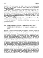
T = D - Y + H + C
H/2
2
S = D - Y - H
Figure 10.17 Shaft and hub dimensions.
Table 10.2 Standard Square Keys and Keyways (inches)*
Diameter Of Holes
(Inclusive)
Keyways
Key StockWidth Depth
5
⁄
16
to
7
⁄
16
3
⁄
32
3
⁄
64
3
⁄
32
Â
3
⁄
32
1
⁄
2
to
9
⁄
16
1
⁄
8
1
⁄
16
1
⁄
8
Â
1
⁄
8
5
⁄
8
to
7
⁄
8
3
⁄
16
3
⁄
32
3
⁄
16
Â
3
⁄
16
15
⁄
16
to 1-
1
⁄
4
1
⁄
4
1
⁄
8
1
⁄
4
Â
1
⁄
4
1-
5
⁄
16
to 1-
3
⁄
8
5
⁄
16
5
⁄
32
5
⁄
16
Â
5
⁄
16
1-
7
⁄
16
to 1-
3
⁄
4
3
⁄
8
3
⁄
16
3
⁄
8
Â
3
⁄
8
1-
13
⁄
16
to 2-
1
⁄
4
1
⁄
2
1
⁄
4
1
⁄
2
Â
1
⁄
2
2-
5
⁄
16
to 2-
3
⁄
4
5
⁄
8
5
⁄
16
5
⁄
8
Â
5
⁄
8
2-
13
⁄
16
to 3-
1
⁄
4
3
⁄
4
3
⁄
8
3
⁄
4
Â
3
⁄
4
3-
5
⁄
16
to 3-
3
⁄
4
7
⁄
8
7
⁄
16
7
⁄
8
Â
7
⁄
8
3-
13
⁄
16
to 4-
1
⁄
2
1
1
⁄
2
1 Â 1
*Square keys are normally used through shaft diameter 4-
1
⁄
2
in.; larger shafts
normally use flat keys.
Source: The Falk Corporation.
Keith Mobley /Maintenance Fundamentals Final Proof 15.6.2004 7:35pm page 194
194 Maintenance Fundamentals
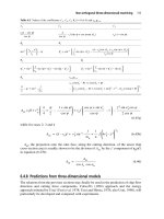
Y ¼
D À
ffiffiffiffiffiffiffiffiffiffiffiffiffiffiffiffiffiffiffi
D
2
À W
2
p
2
where:
C ¼ Allowance or clearance for key, inches
D ¼ Nominal shaft or bore diameter, inches
Table 10.3 Standard Flat Keys and Keyways (inches)
Diameter Of Holes
(Inclusive)
Keyways
Key StockWidth Depth
1
⁄
2
to
9
⁄
16
00
1
⁄
8
3
⁄
64
1
⁄
8
Â
1
⁄
32
5
⁄
8
to
7
⁄
8
00
3
⁄
16
1
⁄
16
3
⁄
16
Â
1
⁄
8
15
⁄
16
to 1-
1
⁄
4
00
1
⁄
4
3
⁄
32
1
⁄
4
Â
3
⁄
16
1-
5
⁄
16
to 1-
3
⁄
8
00
5
⁄
16
1
⁄
8
5
⁄
16
Â
1
⁄
4
1-
7
⁄
16
to 1-
3
⁄
4
00
3
⁄
8
1
⁄
8
3
⁄
8
Â
1
⁄
4
1-
13
⁄
16
to 2-
1
⁄
4
00
1
⁄
2
3
⁄
16
1
⁄
2
Â
3
⁄
8
2-
5
⁄
16
to 2-
3
⁄
4
00
5
⁄
8
7
⁄
32
5
⁄
8
Â
7
⁄
16
2-
13
⁄
16
to 3-
1
⁄
4
00
3
⁄
4
1
⁄
4
3
⁄
4
Â
1
⁄
2
3-
5
⁄
16
to 3-
3
⁄
4
00
7
⁄
8
5
⁄
16
7
⁄
8
Â
5
⁄
8
3-
13
⁄
16
to 4-
1
⁄
2
00
1
3
⁄
8
1 Â
3
⁄
4
4-
9
⁄
16
to 5-
1
⁄
2
00
1-
1
⁄
4
7
⁄
16
1
1
⁄
4
Â
7
⁄
8
5-
9
⁄
16
to 6-
1
⁄
2
00
1-
1
⁄
2
1
⁄
2
1-
1
⁄
2
 1
6-
9
⁄
16
to 7-
1
⁄
2
00
1-
3
⁄
4
5
⁄
8
1-
3
⁄
4
Â
1
⁄
4
7-
9
⁄
16
to 9
00
2
3
⁄
4
2 Â 1-
3
⁄
4
9-
1
⁄
16
to 11
00
2-
1
⁄
2
7
⁄
8
2-
1
⁄
2
 1-
3
⁄
4
11-
1
⁄
16
to 13
00
313Â 2
13-
1
⁄
16
to 15
00
3-
1
⁄
2
1-
1
⁄
4
3-
1
⁄
2
 2-
1
⁄
2
15-
1
⁄
6
to 18
00
41-
1
⁄
2
4 Â 3
18-
1
⁄
16
to 22
00
51-
3
⁄
4
5 Â 3
1
⁄
2
22-
1
⁄
16
to 26
00
64
26-
1
⁄
16
to 30
00
75
Source: The Falk Corporation.
Keith Mobley /Maintenance Fundamentals Final Proof 15.6.2004 7:35pm page 195
Couplings 195
H ¼ Nominal key height, inches
W ¼ Nominal key width, inches
Y ¼ Chordal height, inches
Note: Tables shown below are prepared for manufacturing use. Dimensions
given are for standard shafts and keyways.
KEYWAY MANUFACTURING TOLERANCES
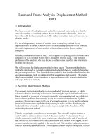
Keyway manufacturing tolerances (illustrated in Figure 10.18) are referred to as
offset (centrality) and lead (cross axis). Offset or centrality is referred to as
Dimension ‘‘N’’; lead or cross axis is referred to as Dimension ‘‘J.’’ Both must
be kept within permissible tolerances, usually 0.002 in.
Offset or Centrality
Shaft
Bore
Keyseat
A
N
Lead or Cross Axis
Shaft
Keyseat
Keyseat
Bore
Lead
Lead
B
Figure 10.18 Manufacturing tolerances. A, Offset. B, Lead.
Keith Mobley /Maintenance Fundamentals Final Proof 15.6.2004 7:35pm page 196
196 Maintenance Fundamentals
KEY STRESS CALCULATIONS
Calculations for shear and compressive key stresses are based on the following
assumptions:
1. The force acts at the radius of the shaft.
2. The force is uniformly distributed along the key length.
3. None of the tangential load is carried by the frictional fit between
shaft and bore.
The shear and compressive stresses in a key are calculated using the following
equations (see Figure 10.19):
Ss ¼
2T
(d) Â (w) Â(L)
Sc ¼
2T
(d) Â (h
1
) Â(L)
where:
d ¼ Shaft diameter, inches (use average diameter for taper shafts)
h
1
¼ Height of key in the shaft or hub that bears against the keyway,
inches. Should equal h
2
for square keys. For designs where
unequal portions of the key are in the hub or shaft, h
1
is the
minimum portion.
Hp ¼ Power, horsepower
L ¼ Effective length of key, inches
RPM ¼ Revolutions per minute
Ss ¼ Shear stress, psi
Sc ¼ Compressive stress, psi
T ¼ Shaft torque, lb-in. or
Hp  63000
RPM
w ¼ Key width, inches
Figure 10.19 Measurements used in calculating shear and compressive key stress.
Keith Mobley /Maintenance Fundamentals Final Proof 15.6.2004 7:35pm page 197
Couplings 197
Key material is usually AISI 1018 or AISI 1045. Table 10.4 provides the allow-
able stresses for these materials.
Example: Select a key for the following conditions: 300 Hp at 600 RPM; 3-inch
diameter shaft,
3
⁄
4
-inch Â
3
⁄
4
-inch key, 4-inch key engagement length.
T ¼ Torque ¼
Hp  63; 000
RPM
¼
300 Â63; 000
600
¼ 31; 500 in-lbs
Ss ¼
2T
d Âw ÂL
¼
2 Â31; 500
3 Â3=4 Â4
¼ 7; 000 psi
Sc ¼
2T
d Âh
1
 L
¼
2 Â31; 500
3 Â3=8 Â4
¼ 14; 000 psi
The AISI 1018 key can be used since it is within allowable stresses listed in Table
10.4 (allowable Ss ¼ 7,500, allowable Sc ¼ 5,000).
Note: If shaft had been 2-
3
⁄
4
-in. diameter (4-in. hub), the key would be
5
⁄
8
-in. Â
5
⁄
8
-in., Ss ¼ 9,200 psi, Sc ¼ 18,400 psi, and a heat-treated key of AISI 1045 would
have been required (allowable Ss ¼ 15,000, allowable Sc ¼ 30,000).
SHAFT STRESS CALCULATIONS
Torsional stresses are developed when power is transmitted through shafts. In
addition, the tooth loads of gears mounted on shafts create bending stresses.
Shaft design, therefore, is based on safe limits of torsion and bending.
To determine minimum shaft diameter in inches:
Minimum Shaft Diameter ¼
ffiffiffiffiffiffiffiffiffiffiffiffiffiffiffiffiffiffiffiffiffiffiffiffiffiffiffiffiffiffiffiffiffiffiffiffiffiffiffiffiffiffiffiffiffiffiffiffiffiffiffi
Hp  321000
RPM ÂAllowable Stress
3
r
Table 10.4 Allowable Stresses for AISI 1018 and AISI 1045
Material
Heat
Treatment
Allowable Stresses – psi
Shear Compressive
AISI 1018 None 7,500 15,000
AISI 1045 255-300 Bhn 15,000 30,000
Source: The Falk Corporation.
Keith Mobley /Maintenance Fundamentals Final Proof 15.6.2004 7:35pm page 198
198 Maintenance Fundamentals
Example:
Hp ¼ 300
RPM ¼ 30
Material ¼ 225 Brinell
From Figure 10.20 at 225 Brinell, Allowable Torsion ¼ 8000 psi
Minimum Shaft Diameter ¼
ffiffiffiffiffiffiffiffiffiffiffiffiffiffiffiffiffiffiffiffiffiffiffiffiffiffiffiffi
300 Â321000
30 Â 8000
3
r
¼
ffiffiffiffiffiffiffiffi
402
3
p
¼ 7:38 inches
From Table 10.5, note that the cube of 7-
1
⁄
4
in. is 381, which is too small (i.e.,
<402) for this example. The cube of 7-
1
⁄
2
in. is 422, which is large enough.
To determine shaft stress, psi:
Shaft Stress ¼
Hp Â321; 000
RPM Âd
3
TENSILE STRENGTH, 1000 PSI (APPROX.)
BRINELL HARDNESS
80
160 200 240 280 320 360 400 440
100 120 140 160 180 200
220
20000
16000
12000
8000
24000
4000
ALLOWABLE TENSILE STRENGTH (psi)
Bending
Torsion
Figure 10.20 Allowable stress as a function of Brinell hardness.
Keith Mobley /Maintenance Fundamentals Final Proof 15.6.2004 7:35pm page 199
Couplings 199
Example: Given 7-
1
⁄
2
-in. shaft for 300 Hp at 30 RPM
Shaft Stress ¼
300 Â321; 000
30 Â (7 À
1
=
2
)
3
¼ 7; 600 psi
Note: The 7-
1
⁄
4
-in. diameter shaft would be stressed to 8420 psi
Table 10.5 Shaft Diameters (Inches) and Their Cubes (Cubic Inches)
DD
3
DD
3
DD
3
1 1.00 5 125.0 9 729
1-
1
⁄
4
1.95 5-
1
⁄
4
145 9-
1
⁄
2
857
1-
1
⁄
2
3.38 5-
1
⁄
2
166.4 10 1000
1-
3
⁄
4
5.36 5-
3
⁄
4
190.1 10-
1
⁄
2
1157
2 8.00 6 216 11 1331
2-
1
⁄
4
11.39 6-
1
⁄
4
244 11-
1
⁄
2
1520
2-
1
⁄
2
15.63 6-
1
⁄
2
275 12 1728
2-
3
⁄
4
20.80 6-
3
⁄
4
308 12-
1
⁄
2
1953
3 27.00 7 343 13 2197
3-
1
⁄
4
34.33 7-
1
⁄
4
381 14 2744
3-
1
⁄
2
42.88 7-
1
⁄
2
422 15 3375
3-
3
⁄
4
52.73 7-
3
⁄
4
465 16 4096
4 64.00 8 512 17 4913
4-
1
⁄
4
76.77 8-
1
⁄
4
562 18 5832
4-
1
⁄
2
91.13 8-
1
⁄
2
614 19 6859
4-
3
⁄
4
107.2 8-
3
⁄
4
670 20 8000
Source: The Falk Corporation.
Keith Mobley /Maintenance Fundamentals Final Proof 15.6.2004 7:35pm page 200
200 Maintenance Fundamentals
11
GEARS AND GEARBOXES
A gear is a form of disc, or wheel, that has teeth around its periphery for the
purpose of providing a positive drive by meshing the teeth with similar teeth on
another gear or rack.
SPUR GEARS
The spur gear might be called the basic gear since all other types have been
developed from it. Its teeth are straight and parallel to the center bore line, as
shown in Figure 11.1. Spur gears may run together with other spur gears or
parallel shafts, with internal gears on parallel shafts, and with a rack. A rack
such as the one illustrated in Figure 11.2 is in effect a straight-line gear. The
smallest of a pair of gears (Figure 11.3) is often called a pinion.
The involute profile or form is the one most commonly used for gear teeth. It is a
curve that is traced by a point on the end of a taut line unwinding from a circle.
The larger the circle, the straighter the curvature; for a rack, which is essentially a
section of an infinitely large gear, the form is straight or flat. The generation of
an involute curve is illustrated in Figure 11.4.
The involute system of spur gearing is based on a rack having straight, or flat,
sides. All gears made to run correctly with this rack will run with each other. The
sides of each tooth incline toward the center top at an angle called the pressure
angle, shown in Figure 11.5.
The 14.5-degree pressure angle was standard for many years. In recent years,
however, the use of the 20-degree pressure angle has been growing, and today,
Keith Mobley /Maintenance Fundamentals Final Proof 15.6.2004 7:38pm page 201
201
Figure 11.1 Example of a spur gear.
Figure 11.2 Rack or straight-line gear.
Figure 11.3 Typical spur gears.
Keith Mobley /Maintenance Fundamentals Final Proof 15.6.2004 7:38pm page 202
202 Maintenance Fundamentals
14.5-degree gearing is generally limited to replacement work. The principal
reasons are that a 20-degree pressure angle results in a gear tooth with greater
strength and wear resistance and permits the use of pinions with a few fewer teeth.
The effect of the pressure angle on the tooth of a rack is shown in Figure 11.6.
It is extremely important that the pressure angle be known when gears are mated,
as all gears that run together must have the same pressure angle. The pressure
angle of a gear is the angle between the line of action and the line tangent to the
Figure 11.4 Invlute curve.
Figure 11.5 Pressure angle.
Keith Mobley /Maintenance Fundamentals Final Proof 15.6.2004 7:38pm page 203
Gears and Gearboxes 203
pitch circles of mating gears. Figure 11.7 illustrates the relationship of the
pressure angle to the line of action and the line tangent to the pitch circles.
PITCH DIAMETER AND CENTER DISTANCE
Pitch circles have been defined as the imaginary circles that are in contact when
two standard gears are in correct mesh. The diameters of these circles are the
pitch diameters of the gears. The center distance of the two gears, therefore,
when correctly meshed, is equal to one half of the sum of the two pitch diam-
eters, as shown in Figure 11.8.
This relationship may also be stated in an equation and may be simplified by
using letters to indicate the various values, as follows:
Figure 11.6 Different pressure angles on gear teeth.
Figure 11.7 Relationship of the pressure angle to the line of action.
Keith Mobley /Maintenance Fundamentals Final Proof 15.6.2004 7:38pm page 204
204 Maintenance Fundamentals
C ¼ Center distance
D
1
¼ First pitch diameter
D
2
¼ Second pitch diameter
C ¼
D
1
þ D
2
2
D
1
¼ 2C ÀD
2
D
2
¼ 2C ÀD
1
Example: The center distance can be found if the pitch diameters are known
(Figure 11.9).
CIRCULAR PITCH
A specific type of pitch designates the size and proportion of gear teeth. In
gearing terms, there are two specific types of pitch: circular pitch and diametrical
pitch. Circular pitch is simply the distance from a point on one tooth to a
corresponding point on the next tooth, measured along the pitch line or circle,
as illustrated in Figure 11.10. Large-diameter gears are frequently made to
circular pitch dimensions.
Figure 11.8 Pitch diameter and center distance.
Figure 11.9 Determining center distance.
Keith Mobley /Maintenance Fundamentals Final Proof 15.6.2004 7:38pm page 205
Gears and Gearboxes 205
DIAMETRICAL PITCH AND MEASUREMENT
The diametrical pitch system is the most widely used, as practically all common-
sized gears are made to diametrical pitch dimensions. It designates the size and
proportions of gear teeth by specifying the number of teeth in the gear for each
inch of the gear’s pitch diameter. For each inch of pitch diameter, there are pi (p)
inches, or 3.1416 in., of pitch-circle circumference. The diametric pitch number
also designates the number of teeth for each 3.1416 in. of pitch-circle circumfer-
ence. Stated in another way, the diametrical pitch number specifies the number
of teeth in 3.1416 in. along the pitch line of a gear.
For simplicity of illustration, a whole-number pitch-diameter gear (4 in.), is
shown in Figure 11.11.
Figure 11.11 illustrates that the diametrical pitch number specifying the
number of teeth per inch of pitch diameter must also specify the number of
Figure 11.10
Figure 11.11 Pitch diameter and diametrical pitch.
Keith Mobley /Maintenance Fundamentals Final Proof 15.6.2004 7:38pm page 206
206 Maintenance Fundamentals
teeth per 3.1416 in. of pitch-line distance. This may be more easily visualized and
specifically dimensioned when applied to the rack in Figure 11.12.
Because the pitch line of a rack is a straight line, a measurement can be easily
made along it. In Figure 11.12, it is clearly shown that there are 10 teeth in
3.1416 in.; therefore the rack illustrated is a 10 diametrical pitch rack.
A similar measurement is illustrated in Figure 11.13, along the pitch line of a
gear. The diametrical pitch being the number of teeth in 3.1416 in. of pitch line,
the gear in this illustration is also a 10 diametrical pitch gear.
In many cases, particularly in machine repair work, it may be desirable for the
mechanic to determine the diametrical pitch of a gear. This may be done very
easily without the use of precision measuring tools, templates, or gauges. Meas-
urements need not be exact because diametrical pitch numbers are usually whole
numbers. Therefore, if an approximate calculation results in a value close to a
whole number, that whole number is the diametrical pitch number of the gear.
The following three methods may be used to determine the approximate diamet-
rical pitch of a gear. A common steel rule, preferably flexible, is adequate to
make the required measurements.
Figure 11.12 Number of teeth in 3.1416 in.
Figure 11.13 Number of teeth in 3.1416 in. on the pitch circle.
Keith Mobley /Maintenance Fundamentals Final Proof 15.6.2004 7:38pm page 207
Gears and Gearboxes 207
METHOD 1
Count the number of teeth in the gear, add 2 to this number, and divide by the
outside diameter of the gear. Scale measurement of the gear to the closest fractional
size is adequate accuracy.
Figure 11.14 illustrates a gear with 56 teeth and an outside measurement of
5
⁄
13
16 in. Adding 2 to 56 gives 58; dividing 58 by 5-
13
⁄
16
gives an answer of 9-
31
⁄
32.
Since this is approximately 10, it can be safely stated that the gear is a 10 decimal
pitch gear.
METHOD 2
Count the number of teeth in the gear and divide this number by the measured
pitch diameter. The pitch diameter of the gear is measured from the root or
bottom of a tooth space to the top of a tooth on the opposite side of the gear.
Figure 11.15 illustrates a gear with 56 teeth. The pitch diameter measured from
the bottom of the tooth space to the top of the opposite tooth is 5-
5
⁄
8
in. Dividing
56 by 5-
5
⁄
8
gives an answer of 9-
15
⁄
16
in. or approximately 10. This method also
indicates that the gear is a 10 decimal pitch gear.
PITCH CALCULATIONS
Diametrical pitch, usually a whole number, denotes the ratio of the number of
teeth to a gear’s pitch diameter. Stated another way, it specifies the number of
teeth in a gear for each inch of pitch diameter. The relationship of pitch
Figure 11.14 Use of Method 1 to approximate the diametrical pitch. In this method the
outside diameter of the gear is measured.
Keith Mobley /Maintenance Fundamentals Final Proof 15.6.2004 7:38pm page 208
208 Maintenance Fundamentals
diameter, diametrical pitch, and number of teeth can be stated mathematically as
follows.
P ¼
N
D
D ¼
N
P
N ¼ D ÂP
where,
D ¼ Pitch diameter
P ¼ Diametrical pitch
N ¼ Number of teeth
If any two values are known, the third may be found by substituting the known
values in the appropriate equation.
Example 1: What is the diametrical pitch of a 40-tooth gear with a 5-in. pitch
diameter?
P ¼
N
D
or P ¼
40
5
or P ¼ 8 diametrical pitch
Example 2: What is the pitch diameter of a 12 diametrical pitch gear with 36
teeth?
D ¼
N
P
or D ¼
36
12
or D ¼ 3-in: pitch diameter
Example 3: How many teeth are there in a 16 diametrical pitch gear with a pitch
diameter of 3–
3
⁄
4
in.?
Figure 11.15 Use of Method 2 to approximate the diametrical pitch. This method uses
the pitch diameter of the gear.
Keith Mobley /Maintenance Fundamentals Final Proof 15.6.2004 7:38pm page 209
Gears and Gearboxes 209
N ¼ D ÂP or N ¼ 3 À3 =4 Â 16 or N ¼ 60 teeth
Circular pitch is the distance from a point on a gear tooth to the corresponding
point on the next gear tooth measured along the pitch line. Its value is equal
to the circumference of the pitch circle divided by the number of teeth in the
gear. The relationship of the circular pitch to the pitch-circle circumference,
number of teeth, and the pitch diameter may also be stated mathematically as
follows:
Circumference of pitch circle ¼ pD
P ¼
D
N
D ¼
PN
N ¼
pD
P
where,
D ¼ Pitch diameter
N ¼ Number of teeth
P ¼ Circular pitch
¼ pi, or 3:1416
If any two values are known, the third may be found by substituting the known
values in the appropriate equation.
Example 1: What is the circular pitch of a gear with 48 teeth and a pitch diameter
of 6 in.?
P ¼
D
N
or
3:1416 Â6
48
or
3:1416
8
or P ¼ :3927 inches
Example 2: What is the pitch diameter of a 0.500-in. circular-pitch gear with 128
teeth?
D ¼
PN
p
or
:5 Â128
3:1416
D ¼ 20:371 inches
The list that follows contains just a few names of the various parts given to gears.
These parts are shown in Figures 11.16 and 11.17.
Addendum: Distance the tooth projects above, or outside, the pitch
line or circle.
Dedendum: Depth of a tooth space below, or inside, the pitch line or
circle.
Keith Mobley /Maintenance Fundamentals Final Proof 15.6.2004 7:38pm page 210
210 Maintenance Fundamentals
Clearance: Amount by which the dedendum of a gear tooth exceeds the
addendum of a matching gear tooth.
Whole Depth: The total height of a tooth or the total depth of a tooth
space.
Working Depth: The depth of tooth engagement of two matching
gears. It is the sum of their addendums.
Tooth Thickness: The distance along the pitch line or circle from one
side of a gear tooth to the other.
TOOTH PROPORTIONS
The full-depth involute system is the gear system in most common use. The
formulas (with symbols) shown below are used for calculating tooth proportions
of full-depth involute gears. Diametrical pitch is given the symbol P as before.
Figure 11.16 Names of gear parts.
Figure 11.17 Names of rack parts.
Keith Mobley /Maintenance Fundamentals Final Proof 15.6.2004 7:38pm page 211
Gears and Gearboxes 211
Addendum, a ¼
1
P
Whole Depth, W
d
¼
2:0 þ :002
P
(20P or smaller)
Dedendum, W
d
¼
2:157
P
(Larger than 20P)
Whole Depth, b ¼ Wd À a
Clearance, c ¼ b Àa
Tooth Thickness, t ¼
1:5708
P
BACKLASH
Backlash in gears is the play between teeth that prevents binding. In terms of
tooth dimensions, it is the amount by which the width of tooth spaces exceeds the
thickness of the mating gear teeth. Backlash may also be described as the
distance, measured along the pitch line, that a gear will move when engaged
with another gear that is fixed or immovable, as illustrated in Figure 11.18.
Normally there must be some backlash present in gear drives to provide running
clearance. This is necessary because binding of mating gears can result in heat
generation, noise, abnormal wear, possible overload, and/or failure of the drive.
A small amount of backlash is also desirable because of the dimensional vari-
ations involved in practical manufacturing tolerances.
Backlash is built into standard gears during manufacture by cutting the gear teeth
thinner than normal by an amount equal to one half the required figure. When two
gears made in this manner are run together, at standard center distance, their
allowances combine, provided the full amount of backlash is required.
Figure 11.18 Backlash.
Keith Mobley /Maintenance Fundamentals Final Proof 15.6.2004 7:38pm page 212
212 Maintenance Fundamentals
On non-reversing drives or drives with continuous load in one direction, the
increase in backlash that results from tooth wear does not adversely affect
operation. However, on reversing drive and drives where timing is critical,
excessive backlash usually cannot be tolerated.
OTHER GEAR TYPES
Many styles and designs of gears have been developed from the spur gear. While
they are all commonly used in industry, many are complex in design and
manufacture. Only a general description and explanation of principles will be
given, as the field of specialized gearing is beyond the scope of this book.
Commonly used styles will be discussed sufficiently to provide the millwright
or mechanic with the basic information necessary to perform installation and
maintenance work.
BEVEL AND MITER
Two major differences between bevel gears and spur gears are their shape and the
relation of the shafts on which they are mounted. The shape of a spur gear is
essentially a cylinder, while the shape of a bevel gear is a cone. Spur gears are
used to transmit motion between parallel shafts, while bevel gears transmit
motion between angular or intersecting shafts. The diagram in Figure 11.19
illustrates the bevel gear’s basic cone shape. Figure 11.20 shows a typical pair
of bevel gears.
Special bevel gears can be manufactured to operate at any desired shaft angle, as
shown in Figure 11.21. Miter gears are bevel gears with the same number of teeth
in both gears operating on shafts at right angles or at 90 degrees, as shown in
Figure 11.22.
A typical pair of straight miter gears is shown in Figure 11.23. Another style of
miter gears having spiral rather than straight teeth is shown in Figure 11.24. The
spiral-tooth style will be discussed later.
The diametrical pitch number as is done with spur gears establishes the tooth size
of bevel gears. Because the tooth size varies along its length, it must be measured
at a given point. This point is the outside part of the gear where the tooth is the
largest. Because each gear in a set of bevel gears must have the same angles and
tooth lengths, as well as the same diametrical pitch, they are manufactured and
distributed only in mating pairs. Bevel gears, like spur gears, are manufactured in
both the 14.5-degree and 20-degree pressure-angle designs.
Keith Mobley /Maintenance Fundamentals Final Proof 15.6.2004 7:38pm page 213
Gears and Gearboxes 213