Maintenance Fundamentals Episode 2 part 2 docx
Bạn đang xem bản rút gọn của tài liệu. Xem và tải ngay bản đầy đủ của tài liệu tại đây (860.86 KB, 20 trang )
Figure 11.19 Basic shape of bevel gears.
Figure 11.20 Typical set of bevel gears.
Keith Mobley /Maintenance Fundamentals Final Proof 15.6.2004 7:38pm page 214
214 Maintenance Fundamentals
Figure 11.21 Shaft angle, which can be at any degree.
Figure 11.22 Miter gears, which are shown at 90 degrees.
HELICAL
Helical gears are designed for parallel-shaft operation like the pair in Figure 11.25.
They are similar to spur gears except that the teeth are cut at an angle to the
centerline. The principal advantage of this design is the quiet, smooth action that
results fromthe sliding contact of the meshing teeth. Adisadvantage, however, is the
higher friction and wear that accompanies this sliding action. The angle at which the
gear teeth are cut is called the helix angle and is illustrated in Figure 11.26.
It is very important to note that the helix angle may be on either side of the gear’s
centerline. Or if compared with the helix angle of a thread, it may be either a
‘‘right-hand’’ or a ‘‘left-hand’’ helix. The hand of the helix is the same regardless
Keith Mobley /Maintenance Fundamentals Final Proof 15.6.2004 7:38pm page 215
Gears and Gearboxes 215
of how viewed. Figure 11.27 illustrates a helical gear as viewed from opposite
sides; changing the position of the gear cannot change the hand of the tooth’s
helix angle. A pair of helical gears, as illustrated in Figure 11.25, must have the
same pitch and helix angle but must be of opposite hands (one right hand and
one left hand).
Helical gears may also be used to connect nonparallel shafts. When used for this
purpose, they are often called ‘‘spiral’’ gears or crossed-axis helical gears. This
style of helical gearing is shown in Figure 11.28.
WORM
The worm and worm gear, illustrated in Figure 11.29, are used to transmit
motion and power when a high-ratio speed reduction is required. They provide
a steady quiet transmission of power between shafts at right angles. The worm is
Figure 11.23 Typical set of miter gears.
Keith Mobley /Maintenance Fundamentals Final Proof 15.6.2004 7:38pm page 216
216 Maintenance Fundamentals
Figure 11.24 Miter gears with spiral teeth.
Figure 11.25 Typical set of helical gears.
Keith Mobley /Maintenance Fundamentals Final Proof 15.6.2004 7:38pm page 217
Gears and Gearboxes 217
Figure 11.26 The angle at which teeth are cut.
Figure 11.27 Helix angle of teeth: the same no matter from which side the gear is viewed.
Figure 11.28 Typical set of spiral gears.
Keith Mobley /Maintenance Fundamentals Final Proof 15.6.2004 7:38pm page 218
218 Maintenance Fundamentals
Figure 11.29 Typical set of worm gears.
always the driver and the worm gear the driven member. Like helical gears,
worms and worm gears have ‘‘hand.’’ The hand is determined by the direction of
the angle of the teeth. Thus, for a worm and worm gear to mesh correctly, they
must be the same hand.
The most commonly used worms have either one, two, three, or four separate
threads and are called single, double, triple, and quadruple thread worms. The
number of threads in a worm is determined by counting the number of starts or
entrances at the end of the worm. The thread of the worm is an important feature
in worm design, as it is a major factor in worm ratios. The ratio of a mating
worm and worm gear is found by dividing the number of teeth in the worm gear
by the number of threads in the worm.
HERRINGBONE
To overcome the disadvantage of the high end thrust present in helical gears, the
herringbone gear, illustrated in Figure 11.30, was developed. It consists simply of
two sets of gear teeth, one right hand and one left hand, on the same gear. The
gear teeth of both hands cause the thrust of one set to cancel out the thrust of
Keith Mobley /Maintenance Fundamentals Final Proof 15.6.2004 7:38pm page 219
Gears and Gearboxes 219
the other. Thus the advantage of helical gears is obtained, and quiet, smooth
operation at higher speeds is possible. Obviously they can only be used for
transmitting power between parallel shafts.
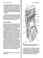
GEAR DYNAMICS AND FAILURE MODES
Many machine-trains utilize gear drive assemblies to connect the driver to the
primary machine. Gears and gearboxes typically have several vibration spectra
associated with normal operation. Characterization of a gearbox’s vibration
signature box is difficult to acquire but is an invaluable tool for diagnosing
machine-train problems. The difficulty is that (1) it is often difficult to mount
the transducer close to the individual gears, and (2) the number of vibration
sources in a multi-gear drive results in a complex assortment of gear mesh,
modulation, and running frequencies. Severe drive-train vibrations (gearbox)
are usually due to resonance between a system’s natural frequency and the
speed of some shaft. The resonant excitation arises from, and is proportional
to, gear inaccuracies that cause small periodic fluctuations in pitch-line velocity.
Complex machines usually have many resonance zones within their operating
speed range because each shaft can excite a system resonance. At resonance these
cyclic excitations may cause large vibration amplitudes and stresses.
Basically, forcing torque arising from gear inaccuracies is small. However, under
resonant conditions torsional amplitude growth is restrained only by damping in
that mode of vibration. In typical gearboxes this damping is often small and
permits the gear-excited torque to generate large vibration amplitudes under
resonant conditions.
Figure 11.30 Herringbone gear.
Keith Mobley /Maintenance Fundamentals Final Proof 15.6.2004 7:38pm page 220
220 Maintenance Fundamentals
One other important fact about gear sets is that all gear sets have a designed
preload and create an induced load (thrust) in normal operation. The direction,
radial or axial, of the thrust load of typical gear sets will provide some insight
into the normal preload and induced loads associated with each type of gear.
To implement a predictive maintenance program, a great deal of time should be
spent understanding the dynamics of gear/gearbox operation and the frequencies
typically associated with the gearbox. As a minimum, the following should be
identified.
Gears generate a unique dynamic profile that can be used to evaluate gear
condition. In addition, this profile can be used as a tool to evaluate the operating
dynamics of the gearbox and its related process system.
Gear Damage
All gear sets create a frequency component, called gear mesh. The fundamental
gear mesh frequency is equal to the number of gear teeth times the running speed
of the shaft. In addition, all gear sets will create a series of side bands or
modulations that will be visible on both sides of the primary gear mesh fre-
quency. In a normal gear set, each of the side bands will be spaced at exactly the
1X or running speed of the shaft and the profile of the entire gear mesh will be
symmetrical.
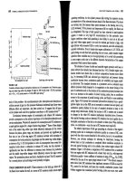
Normal Profile
In a normal gear set, each of the side bands will be spaced at exactly the 1X
running speed of the input shaft, and the entire gear mesh will be symmetrical. In
addition, the side bands will always occur in pairs, one below and one above the
gear mesh frequency. The amplitude of each of these pairs will be identical. For
example, the side band pair indicated as À1 and þ1 in Figure 11.31 will be
spaced at exactly input speed and have the same amplitude.
If the gear mesh profile were split by drawing a vertical line through the actual
mesh (i.e., number of teeth times the input shaft speed), the two halves would be
exactly identical. Any deviation from a symmetrical gear mesh profile is indica-
tive of a gear problem. However, care must be exercised to ensure that the
problem is internal to the gears and induced by outside influences. External
misalignment, abnormal induced loads, and a variety of other outside influences
will destroy the symmetry of the gear mesh profile. For example, the single
reduction gearbox used to transmit power to the mold oscillator system on a
continuous caster drives two eccentrics. The eccentric rotation of these two
cams is transmitted directly into the gearbox and will create the appearance of
Keith Mobley /Maintenance Fundamentals Final Proof 15.6.2004 7:38pm page 221
Gears and Gearboxes 221
eccentric meshing of the gears. The spacing and amplitude of the gear mesh
profile will be destroyed by this abnormal induced load.
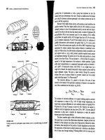
Excessive Wear
Figure 11.32 illustrates a typical gear profile with worn gears. Note that the
spacing between the side bands becomes erratic and they are no longer spaced at
the input shaft speed. The side bands will tend to vary between the input and
output speeds but will not be evenly spaced.
FREQUENCY
GEARMESH
AMPLITUDE
Figure 11.31 Normal profile is symmetrical.
FREQUENCY
GEARMESH
AMPLITUDE
Figure 11.32 Wear or excessive clearance changes side band spacing.
Keith Mobley /Maintenance Fundamentals Final Proof 15.6.2004 7:38pm page 222
222 Maintenance Fundamentals
In addition to gear tooth wear, center-to-center distance between shafts will create
an erratic spacing and amplitude. If the shafts are too close together, the spacing
will tend to be at input shaft speed, but the amplitude will drop drastically. Because
the gears are deeply meshed (i.e., below the normal pitch line), the teeth will
maintain contact through the entire mesh. This loss of clearance will result in
lower amplitudes but will exaggerate any tooth profile defect that may be present.
If the shafts are too far apart, the teeth will mesh above the pitch line. This type
of meshing will increase the clearance between teeth and amplify the energy of
the actual gear mesh frequency and all of its side bands. In addition, the load-
bearing characteristics of the gear teeth will be greatly reduced. Since the pres-
sure is focused on the tip of each tooth, there is less cross-section and strength in
the teeth. The potential for tooth failure is increased in direct proportion the
amount of excess clearance between shafts.
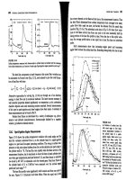
Cracked Or Broken Tooth
Figure 11.33 illustrates the profile of a gear set with a broken tooth. As the gear
rotates, the space left by the chipped or broken tooth will increase the mechan-
ical clearance between the pinion and bull gear. The result will be a low ampli-
tude side band that will occur to the left of the actual gear mesh frequency. When
the next, undamaged teeth mesh, the added clearance will result in a higher-
energy impact.
The resultant side band, to the right of the mesh frequency, will have much
higher amplitude. The paired side bands will have non-symmetrical amplitude
that represents this disproportional clearance and impact energy.
FREQUENCY
GEARMESH
CRACKED OR BROKEN TOOTH
AMPLITUDE
Figure 11.33 A broken tooth will produce an asymmetrical side band profile.
Keith Mobley /Maintenance Fundamentals Final Proof 15.6.2004 7:38pm page 223
Gears and Gearboxes 223
If the gear set develops problems, the amplitude of the gear mesh frequency will
increase and the symmetry of the side bands will change. The pattern illustrated
In Figure 11.34 is typical of a defective gear set. Note the asymmetrical relation-
ship of the side bands.
COMMON CHARACTERISTICS
You should have a clear understanding of the types of gears generally utilized in
today’s machinery, how they interact, and the forces they generate on a rotating
shaft. There are two basic classifications of gear drives: (1) shaft centers parallel,
and (2) shaft centers not parallel. Within these two classifications are several
typical gear types.
Shaft Centers Parallel
There are four basic gear types that are typically used in this classification. All
are mounted on parallel shafts and, unless an idler gear is also used, will have
opposite rotation between the drive and driven gear (if the drive gear has a
clockwise rotation, then the driven gear will have a counter-clockwise rotation).
The gear sets commonly used in machinery include the following.
Spur Gears
The shafts are in the same plane and parallel. The teeth are cut straight and
parallel to the axis of the shaft rotation. No more than two sets of teeth are in
1X
FREQUENCY
GEARMESH
AMPLITUDE
1X 1X 1X 1X 1X
Figure 11.34 Typical defective gear mesh signature.
Keith Mobley /Maintenance Fundamentals Final Proof 15.6.2004 7:38pm page 224
224 Maintenance Fundamentals
mesh at one time, so the load is transferred from one tooth to the next tooth
rapidly. Usually spur gears are used for moderate to low speed applications.
Rotation of spur gear sets is opposite unless one or more idler gears are included
in the gearbox. Typically, spur gear sets will generate a radial load (preload)
opposite the mesh on their shaft support bearings and little or no axial load.
Backlash is an important factor in proper spur gear installation. A certain
amount of backlash must be built into the gear drive allowing for tolerances in
concentricity and tooth form. Insufficient backlash will cause early failure be-
cause of overloading.
As indicated in Figure 11.11, spur gears by design have a preload opposite the
mesh and generate an induced load, or tangential force (TF) in the direction of
rotation. This force can be calculated as:
TF ¼
126, 000 Ã HP
D
p
à RPM
In addition, a spur gear will generate a separating force, S
TF
, that can be
calculated as:
S
TF
¼ TF Ãtan f
where
TF ¼ Tangential Force
HP ¼ Input horsepower to pinion or gear
D
p
¼ Pitch diameter of pinion or gear
RPM ¼ Speed of pinion or gear
f ¼ Pinion or gear tooth pressure angle
Helical Gears
The shafts are in the same plane and parallel but the teeth are cut at an angle to the
centerline of the shafts. Helical teeth have an increased length of contact, run
quieter and have a greater strength and capacity than spur gears. Normally the
angle created by a linethrough the center of the tooth and a line parallel to the shaft
axis is 45 degrees. However, other angles may be found in machinery. Helical gears
also have a preload by design; the critical force to be considered, however, is the
thrust load (axial) generated in normal operation; see Figure 11.12.
TF ¼
126, 000 Ã HP
D
p
à RPM
Keith Mobley /Maintenance Fundamentals Final Proof 15.6.2004 7:38pm page 225
Gears and Gearboxes 225
S
TF
¼
TF Ãtan f
cos l
T
TF
¼ TF Ãtan l
where
TF ¼ Tangential Force
S
TF
¼ Separating Force
T
TF
¼ Thrust Force
HP ¼ Input horsepower to pinion or gear
D
p
¼ Pitch diameter of pinion or gear
RPM ¼ Speed of pinion or gear
f ¼ Pinion or gear tooth pressure angle
l ¼ Pinion or gear helix angle
Herringbone Gears
These are commonly called double helical because they have teeth cut with right
and left helix angles. They are used for heavy loads at medium to high speeds.
They do not have the inherent thrust forces that are present in helical gear sets.
Herringbone gears, by design, cancel the axial loads associated with a single
helical gear. The typical loads associated with herringbone gear sets are the
radial side-load created by gear mesh pressure and a tangential force in the
direction of rotation.
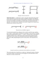
Internal Gears
Internal gears can be run only with an external gear of the same type, pitch, and
pressure angle. The preload and induced load will depend on the type of gears
used. Refer to spur or helical for axial and radial forces.
TROUBLESHOOTING
One of the primary causes of gear failure is the fact that, with few exceptions,
gear sets are designed for operation in one direction only. Failure is often caused
by inappropriate bi-directional operation of the gearbox or backward instal-
lation of the gear set. Unless specifically manufactured for bi-directional oper-
ation, the ‘‘non-power’’ side of the gear’s teeth is not finished. Therefore, this side
is rougher and does not provide the same tolerance as the finished ‘‘power’’ side.
Note that it has become standard practice in some plants to reverse the pinion or
bull gear in an effort to extend the gear set’s useful life. While this practice
permits longer operation times, the torsional power generated by a reversed gear
set is not as uniform and consistent as when the gears are properly installed.
Keith Mobley /Maintenance Fundamentals Final Proof 15.6.2004 7:38pm page 226
226 Maintenance Fundamentals
Table 11.1 Common Failure Modes of Gearboxes and Gear Sets
THE PROBLEM
THE CAUSES
Bent Shaft
Broken or Loose Bolts or Setscrews
Damaged Motor
Elliptical Gears
Exceeds Motor’s Brake Horsepower Rating
Excessive or Too Little Backlash
Excessive Torsional Loading
Foreign Object In Gearbox
Gear Set Not Suitable for Application
Gears Mounted Backward on Shafts
Incorrect Center-to-Center Distance Between Shafts
Incorrect Direction of Rotation
Lack of or Improper Lubrication
Misalignment of Gears or Gearbox
Overload
Process Induced Misalignment
Unstable Foundation
Water or Chemicals in Gearbox
Worn Bearings
Worn Coupling
Gear Failures
Variations In Torsional Power
Insufficient Power Output
Overheated Bearings
Short Bearing Life
Overload on Driver
High Vibration
High Noise Levels
Motor Trips
Source: Integrated Systems, Inc.
Keith Mobley /Maintenance Fundamentals Final Proof 15.6.2004 7:38pm page 227
Gears and Gearboxes 227
Gear overload is another leading cause of failure. In some instances, the over-
load is constant, which is an indication that the gearbox is not suitable for the
application. In other cases, the overload is intermittent and only occurs when the
speed changes or when specific production demands cause a momentary spike in
the torsional load requirement of the gearbox.
Misalignment, both real and induced, is also a primary root cause of gear failure.
The only way to ensure that gears are properly aligned is to hard blue the gears
immediately following installation. After the gears have run for a short time,
their wear pattern should be visually inspected. If the pattern does not conform
to vendor’s specifications, alignment should be adjusted.
Poor maintenance practices are the primary source of real misalignment prob-
lems. Proper alignment of gear sets, especially large ones, is not an easy task.
Gearbox manufacturers do not provide an easy, positive means to ensure that
shafts are parallel and that the proper center-to-center distance is maintained.
Induced misalignment is also a common problem with gear drives. Most gear-
boxes are used to drive other system components, such as bridle or process rolls.
If misalignment is present in the driven members (either real or process induced),
it also will directly affect the gears. The change in load zone caused by the
misaligned driven component will induce misalignment in the gear set. The effect
is identical to real misalignment within the gearbox or between the gearbox and
mated (i.e., driver and driven) components.
Visual inspection of gears provides a positive means to isolate the potential root
cause of gear damage or failures. The wear pattern or deformation of gear teeth
provides clues as to the most likely forcing function or cause. The following
sections discuss the clues that can be obtained from visual inspection.
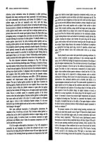
NORMAL WEAR
Figure 11.35 illustrates a gear that has a normal wear pattern. Note that the
entire surface of each tooth is uniformly smooth above and below the pitch line.
ABNORMAL WEAR
Figures 11.36 through 11.39 illustrate common abnormal wear patterns found in
gear sets. Each of these wear patterns suggests one or more potential failure
modes for the gearbox.
Keith Mobley /Maintenance Fundamentals Final Proof 15.6.2004 7:38pm page 228
228 Maintenance Fundamentals
Abrasion
Abrasion creates unique wear patterns on the teeth. The pattern varies,
depending on the type of abrasion and its specific forcing function. Figure
11.36 illustrates severe abrasive wear caused by particulates in the lubricating
oil. Note the score marks that run from the root to the tip of the gear teeth.
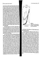
Chemical Attack or Corrosion
Water and other foreign substances in the lubricating oil supply also cause gear
degradation and premature failure. Figure 11.37 illustrates a typical wear pattern
on gears caused by this failure mode.
Figure 11.35 Normal wear pattern.
Figure 11.36 Wear pattern caused by abrasives in lubricating oil.
Keith Mobley /Maintenance Fundamentals Final Proof 15.6.2004 7:38pm page 229
Gears and Gearboxes 229
Overloading
The wear patterns generated by excessive gear loading vary, but all share similar
components. Figure 11.38 illustrates pitting caused by excessive torsional
loading. The pits are created by the implosion of lubricating oil. Other wear
patterns, such as spalling and burning, can also help to identify specific forcing
functions or root causes of gear failure.
Figure 11.37 Pattern caused by corrosive attack on gear teeth.
Figure 11.38 Pitting caused by gear overloading.
Keith Mobley /Maintenance Fundamentals Final Proof 15.6.2004 7:38pm page 230
230 Maintenance Fundamentals
12
COMPRESSORS
Compressors are machines that are used to increase the pressure of a gas or
vapor. They can be grouped into two major classifications, centrifugal and
positive displacement. This section provides a general discussion of these types
of compressors.
CENTRIFUGAL
In general, the centrifugal designation is used when the gas flow is radial and the
energy transfer is predominantly due to a change in the centrifugal forces acting
on the gas. The force utilized by the centrifugal compressor is the same as that
utilized by centrifugal pumps.
In a centrifugal compressor, air or gas at atmospheric pressure enters the eye of
the impeller. As the impeller rotates, the gas is accelerated by the rotating
element within the confined space that is created by the volute of the compres-
sor’s casing. The gas is compressed as more gas is forced into the volute by the
impeller blades. The pressure of the gas increases as it is pushed through the
reduced free space within the volute.
As in centrifugal pumps, there may be several stages to a centrifugal air com-
pressor. In these multi-stage units, a progressively higher pressure is produced by
each stage of compression.
Keith Mobley /Maintenance Fundamentals Final Proof 15.6.2004 7:42pm page 231
231
Configuration
The actual dynamics of centrifugal compressors are determined by their design.
Common designs are overhung or cantilever, centerline, and bull gear.
Overhung or Cantilever
The cantilever design is more susceptible to process instability than centerline
centrifugal compressors. Figure 12.1 illustrates a typical cantilever design.
The overhung design of the rotor (i.e., no outboard bearing) increases the
potential for radical shaft deflection. Any variation in laminar flow, volume, or
load of the inlet or discharge gas forces the shaft to bend or deflect from its true
centerline. As a result, the mode shape of the shaft must be monitored closely.
Centerline
Centerline designs, such as horizontal and vertical split-case, are more stable
over a wider operating range, but should not be operated in a variable-demand
system. Figure 12.2 illustrates the normal airflow pattern through a horizontal
split-case compressor. Inlet air enters the first stage of the compressor, where
pressure and velocity increases occur. The partially compressed air is routed to
the second stage, where the velocity and pressure are increased further. Adding
Figure 12.1 Cantilever centrifugal compressor is susceptible to instability.
Keith Mobley /Maintenance Fundamentals Final Proof 15.6.2004 7:42pm page 232
232 Maintenance Fundamentals
additional stages until the desired final discharge pressure is achieved can con-
tinue this process.
Two factors are critical to the operation of these compressors: impeller configur-
ation and laminar flow, which must be maintained through all of the stages.
The impeller configuration has a major impact on stability and operating envel-
ope. There are two impeller configurations, inline and back-to-back, or opposed.
With the inline design, all impellers face in the same direction. With the opposed
design, impeller direction is reversed in adjacent stages.
Inline A compressor with all impellers facing in the same direction generates
substantial axial forces. The axial pressures generated by each impeller for all the
stages are additive. As a result, massive axial loads are transmitted to the fixed
bearing. Because of this load, most of these compressors use either a Kingsbury
thrust bearing or a balancing piston to resist axial thrusting.
Figure 12.3 illustrates a typical balancing piston.
All compressors that use inline impellers must be monitored closely for axial
thrusting. If the compressor is subjected to frequent or constant unloading, the
axial clearance will increase because of this thrusting cycle. Ultimately, this
frequent thrust loading will lead to catastrophic failure of the compressor.
Opposed By reversing the direction of alternating impellers, the axial forces
generated by each impeller or stage can be minimized. In effect, the opposed
Figure 12.2 Airflow through a centerline centrifugal compressor.
Keith Mobley /Maintenance Fundamentals Final Proof 15.6.2004 7:42pm page 233
Compressors 233