SOIL MECHANICS - CHAPTER 34 pot
Bạn đang xem bản rút gọn của tài liệu. Xem và tải ngay bản đầy đủ của tài liệu tại đây (189.83 KB, 6 trang )
Chapter 34
COULOMB
Long before the analysis of Rankine the French scientist Coulomb presented a theory on limiting states of stress in soils (in 1776), which is still
of great value. The theory enables to determine the stresses on a retaining structure for the cases of active and passive earth pressure. The
method is based upon the assumption that the soil fails along straight slip planes.
34.1 Active earth pressure
For the active case (a retreating wall) the procedure is illustrated in Figure 34.1. It is assumed that in case of a displacement of the wall
.
.
.
.
.
.
.
.
.
.
.
.
.
.
.
.
.
.
.
.
.
.
.
.
.
.
.
.
.
.
.
.
.
.
.
.
.
.
.
.
.
.
.
.
.
.
.
.
.
.
.
.
.
.
.
.
.
.
.
.
.
.
.
.
.
.
.
.
.
.
.
.
.
.
.
.
.
.
.
.
.
.
.
.
.
.
.
.
.
.
.
.
.
.
.
.
.
.
.
.
.
.
.
.
.
.
.
.
.
.
.
.
.
.
.
.
.
.
.
.
.
.
.
.
.
.
.
.
.
.
.
.
.
.
.
.
.
.
.
.
.
.
.
.
.
.
.
.
.
.
.
.
.
.
.
.
.
.
.
.
.
.
.
.
.
.
.
.
.
.
.
.
.
.
.
.
.
.
.
.
.
.
.
.
.
.
.
.
.
.
.
.
.
.
.
.
.
.
.
.
.
.
.
.
.
.
.
.
.
.
.
.
.
.
.
.
.
.
.
.
.
.
.
.
.
.
.
.
.
.
.
.
.
.
.
.
.
.
.
.
.
.
.
.
.
.
.
.
.
.
.
.
.
.
.
.
.
.
.
.
.
.
.
.
.
.
.
.
.
.
.
.
.
.
.
.
.
.
.
.
.
.
.
.
.
.
.
.
.
.
.
.
.
.
.
.
.
.
.
.
.
.
.
.
.
.
.
.
.
.
.
.
.
.
.
.
.
.
.
.
.
.
.
.
.
.
.
.
.
.
.
.
.
.
.
.
.
.
.
.
.
.
.
.
.
.
.
.
.
.
.
.
.
.
.
.
.
.
.
.
.
.
.
.
.
.
.
.
.
.
.
.
.
.
.
.
.
.
.
.
.
.
.
.
.
.
.
.
.
.
.
.
.
.
.
.
.
.
.
.
.
.
.
.
.
.
.
.
.
.
.
.
.
.
.
.
.
.
.
.
.
.
.
.
.
.
.
.
.
.
.
.
.
.
.
.
.
.
.
.
.
.
.
.
.
.
.
.
.
.
.
.
.
.
.
.
.
.
.
.
.
.
.
.
.
.
.
.
.
.
.
.
.
.
.
.
.
.
.
.
.
.
.
.
.
.
.
.
.
.
.
.
.
.
.
.
.
.
.
.
.
.
.
.
.
.
.
.
.
.
.
.
.
.
.
.
.
.
.
.
.
.
.
.
.
.
.
.
.
.
.
.
.
.
.
.
.
.
.
.
.
.
.
.
.
.
.
.
.
.
.
.
.
.
.
.
.
.
.
.
.
.
.
.
.
.
.
.
.
.
.
.
.
.
.
.
.
.
.
.
.
.
.
.
.
.
.
.
.
.
.
.
.
.
.
.
.
.
.
.
.
.
.
.
.
.
.
.
.
.
.
.
.
.
.
.
.
.
.
.
.
.
.
.
.
.
.
.
.
.
.
.
.
.
.
.
.
.
.
.
.
.
.
.
.
.
.
.
.
.
.
.
.
.
.
.
.
.
.
.
.
.
.
.
.
.
.
.
.
.
.
.
.
.
.
.
.
.
.
.
.
.
.
.
.
.
.
.
.
.
.
.
.
.
.
.
.
.
.
.
.
.
.
.
.
.
.
.
.
.
.
.
.
.
.
.
.
.
.
.
.
.
.
.
.
.
.
.
.
.
.
.
.
.
.
.
.
.
.
.
.
.
.
.
.
.
.
.
.
.
.
.
.
.
.
.
.
.
.
.
.
.
.
.
.
.
.
.
.
.
.
.
.
.
.
.
.
.
.
.
.
.
.
.
.
.
.
.
.
.
.
.
.
.
.
.
.
.
.
.
.
.
.
.
.
.
.
.
.
.
.
.
.
.
.
.
.
.
.
.
.
.
.
.
.
.
.
.
.
.
.
.
.
.
.
.
.
.
.
.
.
.
.
.
.
.
.
.
.
.
.
.
.
.
.
.
.
.
.
.
.
.
.
.
.
.
.
.
.
.
.
.
.
.
.
.
.
.
.
.
.
.
.
.
.
.
.
.
.
.
.
.
.
.
.
.
.
.
.
.
.
.
.
.
.
.
.
.
.
.
.
.
.
.
.
.
.
.
.
.
.
.
.
.
.
.
.
.
.
.
.
.
.
.
.
.
.
.
.
.
.
.
.
.
.
.
.
.
.
.
.
.
.
.
.
.
.
.
.
.
.
.
.
.
.
.
.
.
.
.
.
.
.
.
.
.
.
.
.
.
.
.
.
.
.
.
.
.
.
.
.
.
.
.
.
.
.
.
.
.
.
.
.
.
.
.
.
.
.
.
.
.
.
.
.
.
.
.
.
.
.
.
.
.
.
.
.
.
.
.
.
.
.
.
.
.
.
.
.
.
.
.
.
.
.
.
.
.
.
.
.
.
.
.
.
.
.
.
.
.
.
.
.
.
.
.
.
.
.
.
.
.
.
.
.
.
.
.
.
.
.
.
.
.
.
.
.
.
.
.
.
.
.
.
.
.
.
.
.
.
.
.
.
.
.
.
.
.
.
.
.
.
.
.
.
.
.
.
.
.
.
.
.
.
.
.
.
.
.
.
.
.
.
.
.
.
.
.
.
.
.
.
.
.
.
.
.
.
.
.
.
.
.
.
.
.
.
.
.
.
.
.
.
.
.
.
.
.
.
.
.
.
.
.
.
.
.
.
.
.
.
.
.
.
.
.
.
.
.
.
.
.
.
.
.
.
.
.
.
.
.
.
.
.
.
.
.
.
.
.
.
.
.
.
.
.
.
.
.
.
.
.
.
.
.
.
.
.
.
.
.
.
.
.
.
.
.
.
.
.
.
.
.
.
.
.
.
.
.
.
.
.
.
.
.
.
.
.
.
.
.
.
.
.
.
.
.
.
.
.
.
.
.
.
.
.
.
.
.
.
.
.
.
.
.
.
.
.
.
.
.
.
.
.
.
.
.
.
.
.
.
.
.
.
.
.
.
.
.
.
.
.
.
.
.
.
.
.
.
.
.
.
.
.
.
.
.
.
.
.
.
.
.
.
.
.
.
.
.
.
.
.
.
.
.
.
.
.
.
.
.
.
.
.
.
.
.
.
.
.
.
.
.
.
.
.
.
.
.
.
.
.
.
.
.
.
.
.
.
.
.
.
.
.
.
.
.
.
.
.
.
.
.
.
.
.
.
.
.
.
.
.
.
.
.
.
.
.
.
.
.
.
.
.
.
.
.
.
.
.
.
.
.
.
.
.
.
.
.
.
.
.
.
.
.
.
.
.
.
.
.
.
.
.
.
.
.
.
.
.
.
.
.
.
.
.
.
.
.
.
.
.
.
.
.
.
.
.
.
.
.
.
.
.
.
.
.
.
.
.
.
.
.
.
.
.
.
.
.
.
.
.
.
.
.
.
.
.
.
.
.
.
.
.
.
.
.
.
.
.
.
.
.
.
.
.
.
.
.
.
.
.
.
.
.
.
.
.
.
.
.
.
.
.
.
.
.
.
.
.
.
.
.
.
.
.
.
.
.
.
.
.
.
.
.
.
.
.
.
.
.
.
.
.
.
.
.
.
.
.
.
.
.
.
.
.
.
.
.
.
.
.
.
.
.
.
.
.
.
.
.
.
.
.
.
.
.
.
.
.
.
.
.
.
.
.
.
.
.
.
.
.
.
.
.
.
.
.
.
.
.
.
.
.
.
.
.
.
.
.
.
.
.
.
.
.
.
.
.
.
.
.
.
.
.
.
.
.
.
.
.
.
.
.
.
.
.
.
.
.
.
.
.
.
.
.
.
.
.
.
.
.
.
.
.
.
.
.
.
.
.
.
.
.
.
.
.
.
.
.
.
.
.
.
.
.
.
.
.
.
.
.
.
.
.
.
.
.
.
.
.
.
.
.
.
.
.
.
.
.
.
.
.
.
.
.
.
.
.
.
.
.
.
.
.
.
.
.
.
.
.
.
.
.
.
.
.
.
.
.
.
.
.
.
.
.
.
.
.
.
.
.
.
.
.
.
.
.
.
.
.
.
.
.
.
.
.
.
.
.
.
.
.
.
.
.
.
.
.
.
.
.
.
.
.
.
.
.
.
.
.
.
.
.
.
.
.
.
.
.
.
.
.
.
.
.
.
.
.
.
.
.
.
.
.
.
.
.
.
.
.
.
.
.
.
.
.
.
.
.
.
.
.
.
.
.
.
.
.
.
.
.
.
.
.
.
.
.
.
.
.
.
.
.
.
.
.
.
.
.
.
.
.
.
.
.
.
.
.
.
.
.
.
.
.
.
.
.
.
.
.
.
.
.
.
.
.
.
.
.
.
.
.
.
.
.
.
.
.
.
.
.
.
.
.
.
.
.
.
.
.
.
.
.
.
.
.
.
.
.
.
.
.
.
.
.
.
.
.
.
.
.
.
.
.
.
.
.
.
.
.
.
.
.
.
.
.
.
.
.
.
.
.
.
.
.
.
.
.
.
.
.
.
.
.
.
.
.
.
.
.
.
.
.
.
.
.
.
.
.
.
.
.
.
.
.
.
.
.
.
.
.
.
.
.
.
.
.
.
.
.
.
.
.
.
.
.
.
.
.
.
.
.
.
.
.
.
.
.
.
.
.
.
.
.
.
.
.
.
.
.
.
.
.
.
.
.
.
.
.
.
.
.
.
.
.
.
.
.
.
.
.
.
.
.
.
.
.
.
.
.
.
.
.
.
.
.
.
.
.
.
.
.
.
.
.
.
.
.
.
.
.
.
.
.
.
.
.
.
.
.
.
.
.
.
.
.
.
.
.
.
.
.
.
.
.
.
.
.
.
.
.
.
.
.
.
.
.
.
.
.
.
.
.
.
.
.
.
.
.
.
.
.
.
.
.
.
.
.
.
.
.
.
.
.
.
.
.
.
.
.
.
.
.
.
.
.
.
.
.
.
.
.
.
.
.
.
.
.
.
.
.
.
.
.
.
.
.
.
.
.
.
.
.
.
.
.
.
.
.
.
.
.
.
.
.
.
.
.
.
.
.
.
.
.
.
.
.
.
.
.
.
.
.
.
.
.
.
.
.
.
.
.
.
.
.
.
.
.
.
.
.
.
.
.
.
.
.
.
.
.
.
.
.
.
.
.
.
.
.
.
.
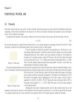
θ
h
N
W
Q
T
Figure 34.1: Active earth pressure.
towards the left, a triangular wedge of soil will slide down, along a straight slip plane.
The angle of the slope with the vertical direction is denoted by θ. It is also assume d
that at the moment of sliding, the weight of the soil wedge is just in equilibrium with
the forces on the slip surface and the forces on the wall. For reasons of simplicity it is
assumed, at least initially, that the force between the soil and the wall (Q) is directed
normal to the surface of the wall, i.e. shear stresses along the wall are initially neglected.
In later chapters such shear stresses will be taken into account as well. The purpose of
the analysis is to determine the magnitude of the force Q. The principle of Coulomb’s
method is that it is stated that the wall must be capable of withstanding the force Q for
all possible slip planes. Therefore the slip plane that leads to the largest value of Q is to
be determined. The various slip planes are characterized by the angle θ, and this angle
will be determined such that the maximum value of Q is obtained.
The starting point of the analysis is the weight of the soil wedge (W ), per unit width perpendicular to the plane shown in the figure,
W =
1
2
γh
2
tan θ. (34.1)
This weight must be balanced by the horizontal force Q (horizontal because the wall has been assumed to be perfectly smooth), and the forces
N and T on the slip plane. The direction of the shear force T is determined by the assumed sliding direction, with the soil body moving down,
in order to follow the motion of the wall to the left. Furthermore, because the length of the slip plane is h/ cos θ,
T =
ch
cos θ
+ N tanφ. (34.2)
189
Arnold Verruijt, Soil Mechanics : 34. COULOMB 190
The equations of equilibrium of the s oil body, in horizontal and vertical direction, are
Q + T sin θ − N cosθ = 0, (34.3)
W −N sin θ − T cos θ = 0. (34.4)
With eq. (34.2) the shear force T can be eliminated. This gives
Q =
N
cos φ
cos(θ + φ) − ch tan θ , (34.5)
W =
N
cos φ
sin(θ + φ) + ch. (34.6)
From these two equations the normal force N can be eliminated,
Q = W
cos(θ + φ)
sin(θ + φ)
− ch
cos φ
cos θ sin(θ + φ)
. (34.7)
With eq. (34.1) this gives
Q =
1
2
γh
2
sin θ cos(θ + φ)
cos θ sin(θ + φ)
− ch
cos φ
cos θ sin(θ + φ)
. (34.8)
This equation expresses the force Q as a function of the angle θ. The relation is rather complex (the angle θ appears in 6 places), so that it
does not seem to be very simple to dete rmine the maximum value. However, the expression can be simplified by using various trigonometric
relations, such as sin θ cos(θ + φ) = cos θ sin(θ + φ) − sin φ. This gives
Q =
1
2
γh
2
−
1
2
γh
2
sin φ + ch cos φ
cos θ sin(θ + φ)
. (34.9)
Now the angle θ appears in 2 places only, in the denominator of the second term. The maximum value of Q can be determined by the maximum
value of the function
f(θ) = cos θ sin(θ + φ).
The maximum of this function occurs when its derivative with respect to θ is zero. Differentiation gives
df
dθ
= cos(2θ + φ),
Arnold Verruijt, Soil Mechanics : 34. COULOMB 191
and a second differentiation gives
d
2
f
dθ
2
= −2 sin(2θ + φ).
It now follows that df/dθ = 0 if 2θ + φ =
1
2
π, or
df
dθ
= 0 : θ =
1
4
π −
1
2
φ. (34.10)
Then d
2
f/dθ
2
= −2, so that the function f indeed has a maximum for this value of θ. This means that the horizontal force Q also has a
maximum for θ =
1
4
π −
1
2
φ. This maximum value is, after some elaboration,
θ =
1
4
π −
1
2
φ : Q =
1
2
γh
2
K
a
− 2ch
K
a
, (34.11)
in which K
a
is the coefficient of active earth pressure, defined before,
K
a
=
1 − sin φ
1 + sin φ
. (34.12)
These results are in full agreement with the results obtained in the previous chapter on active earth pressure, see equation (33.11. The value for
the horizontal force Q corresponds to the sliding of a wedge of soil along a slip plane making an angle
1
4
π −
1
2
φ with the vertical direction. These
are just the planes shown in Figure 33.3. In the previous chapter it was found that along these planes the stresses first reach the Mohr-Coulomb
envelope. It might be noted that in this analysis possible tension cracks in the soil have been ignored.
Coulomb’s method contains a possible confusing step, in the pro c edure of maximizing the force Q to determine the appropriate value of the
angle θ. This might suggest that the procedure gives a high value for Q, whereas in reality the value of Q indicates the smallest possible value of
the horizontal force against a retaining wall, as can be seen from Rankine’s analysis. The confusion is caused by the assumption in Coulomb’s
analysis that the soil slides along a slope defined by an angle θ with the vertical, and not along any other plane. For a value of θ other than the
critical value θ =
1
4
π −
1
2
φ, the force Q may be smaller, but in that case there will be other planes on which the maximum shear stress exceeds
Coulomb’s maximum τ
f
= c + σ
n
tan φ. In the analysis it ought to be investigated whether the assumed slip plane, at an angle θ , is indeed the
most critical plane. This is the case only if θ =
1
4
π −
1
2
φ, as can b e seen from Rankine’s analysis. In that analysis the stresses on all planes
are considered, by using Mohr’s circle. In Coulomb’s analysis the stresses on planes other than the assumed sliding plane are not considered at all.
In engineering practice, the horizontal stress against a retaining wall, or a sheet pile wall is often calculated using the active stress coefficient
K
a
. This may seem on the unsafe side, because it gives the smallest possible value of the horizontal stress, and will o cc ur only in case of failure
of the soil. The application is based upon the following argumentation. It is admitted that the analysis following Rankine or Coulomb, for the
active stress state, yields the smallest possible value for the lateral force. In reality the lateral force may be higher, espe cially if the foundation
of the retaining wall is stiff and strong. If the lateral force is so large that the wall’s foundation can not withstand that force, it will deform,
Arnold Verruijt, Soil Mechanics : 34. COULOMB 192
away from the soil. During that deformation the lateral force will decrease. Eventually this deformation may be so large that the active state
of stress is attained. If the foundation and the structure are strong enough to withstand the active state of stress, the deformations will stop
as soon as this active state is reached. These deformations may be large, but the structure will not fail. Thus, the structure will be safe if
it can withstand active earth pressure, provided that there is no objection to a considerable deformation. For instance, the pile foundation of
a quay wall in a harb or can be designed on the basis of active earth pressure against the quay wall, if it is accepted that considerable lateral
deformations (say 1 % or 2 % of the height of the wall) of the quay wall may occur. If this is undesirable, for esthetic reasons or because other
structures (the cranes) might be damaged by such large deformations, the foundation must be designed for larger lateral forces. This will mean
that many more piles are needed.
34.2 Passive earth pressure
For the case of passive earth pressure (i.e. the case of a wall that is being pushed towards the soil mass, by some external cause) Coulomb’s
procedure is as follows, see Figure 34.2. Because the wedge of soil in this case is being pushed upwards, the shear force T will be acting in
.
.
.
.
.
.
.
.
.
.
.
.
.
.
.
.
.
.
.
.
.
.
.
.
.
.
.
.
.
.
.
.
.
.
.
.
.
.
.
.
.
.
.
.
.
.
.
.
.
.
.
.
.
.
.
.
.
.
.
.
.
.
.
.
.
.
.
.
.
.
.
.
.
.
.
.
.
.
.
.
.
.
.
.
.
.
.
.
.
.
.
.
.
.
.
.
.
.
.
.
.
.
.
.
.
.
.
.
.
.
.
.
.
.
.
.
.
.
.
.
.
.
.
.
.
.
.
.
.
.
.
.
.
.
.
.
.
.
.
.
.
.
.
.
.
.
.
.
.
.
.
.
.
.
.
.
.
.
.
.
.
.
.
.
.
.
.
.
.
.
.
.
.
.
.
.
.
.
.
.
.
.
.
.
.
.
.
.
.
.
.
.
.
.
.
.
.
.
.
.
.
.
.
.
.
.
.
.
.
.
.
.
.
.
.
.
.
.
.
.
.
.
.
.
.
.
.
.
.
.
.
.
.
.
.
.
.
.
.
.
.
.
.
.
.
.
.
.
.
.
.
.
.
.
.
.
.
.
.
.
.
.
.
.
.
.
.
.
.
.
.
.
.
.
.
.
.
.
.
.
.
.
.
.
.
.
.
.
.
.
.
.
.
.
.
.
.
.
.
.
.
.
.
.
.
.
.
.
.
.
.
.
.
.
.
.
.
.
.
.
.
.
.
.
.
.
.
.
.
.
.
.
.
.
.
.
.
.
.
.
.
.
.
.
.
.
.
.
.
.
.
.
.
.
.
.
.
.
.
.
.
.
.
.
.
.
.
.
.
.
.
.
.
.
.
.
.
.
.
.
.
.
.
.
.
.
.
.
.
.
.
.
.
.
.
.
.
.
.
.
.
.
.
.
.
.
.
.
.
.
.
.
.
.
.
.
.
.
.
.
.
.
.
.
.
.
.
.
.
.
.
.
.
.
.
.
.
.
.
.
.
.
.
.
.
.
.
.
.
.
.
.
.
.
.
.
.
.
.
.
.
.
.
.
.
.
.
.
.
.
.
.
.
.
.
.
.
.
.
.
.
.
.
.
.
.
.
.
.
.
.
.
.
.
.
.
.
.
.
.
.
.
.
.
.
.
.
.
.
.
.
.
.
.
.
.
.
.
.
.
.
.
.
.
.
.
.
.
.
.
.
.
.
.
.
.
.
.
.
.
.
.
.
.
.
.
.
.
.
.
.
.
.
.
.
.
.
.
.
.
.
.
.
.
.
.
.
.
.
.
.
.
.
.
.
.
.
.
.
.
.
.
.
.
.
.
.
.
.
.
.
.
.
.
.
.
.
.
.
.
.
.
.
.
.
.
.
.
.
.
.
.
.
.
.
.
.
.
.
.
.
.
.
.
.
.
.
.
.
.
.
.
.
.
.
.
.
.
.
.
.
.
.
.
.
.
.
.
.
.
.
.
.
.
.
.
.
.
.
.
.
.
.
.
.
.
.
.
.
.
.
.
.
.
.
.
.
.
.
.
.
.
.
.
.
.
.
.
.
.
.
.
.
.
.
.
.
.
.
.
.
.
.
.
.
.
.
.
.
.
.
.
.
.
.
.
.
.
.
.
.
.
.
.
.
.
.
.
.
.
.
.
.
.
.
.
.
.
.
.
.
.
.
.
.
.
.
.
.
.
.
.
.
.
.
.
.
.
.
.
.
.
.
.
.
.
.
.
.
.
.
.
.
.
.
.
.
.
.
.
.
.
.
.
.
.
.
.
.
.
.
.
.
.
.
.
.
.
.
.
.
.
.
.
.
.
.
.
.
.
.
.
.
.
.
.
.
.
.
.
.
.
.
.
.
.
.
.
.
.
.
.
.
.
.
.
.
.
.
.
.
.
.
.
.
.
.
.
.
.
.
.
.
.
.
.
.
.
.
.
.
.
.
.
.
.
.
.
.
.
.
.
.
.
.
.
.
.
.
.
.
.
.
.
.
.
.
.
.
.
.
.
.
.
.
.
.
.
.
.
.
.
.
.
.
.
.
.
.
.
.
.
.
.
.
.
.
.
.
.
.
.
.
.
.
.
.
.
.
.
.
.
.
.
.
.
.
.
.
.
.
.
.
.
.
.
.
.
.
.
.
.
.
.
.
.
.
.
.
.
.
.
.
.
.
.
.
.
.
.
.
.
.
.
.
.
.
.
.
.
.
.
.
.
.
.
.
.
.
.
.
.
.
.
.
.
.
.
.
.
.
.
.
.
.
.
.
.
.
.
.
.
.
.
.
.
.
.
.
.
.
.
.
.
.
.
.
.
.
.
.
.
.
.
.
.
.
.
.
.
.
.
.
.
.
.
.
.
.
.
.
.
.
.
.
.
.
.
.
.
.
.
.
.
.
.
.
.
.
.
.
.
.
.
.
.
.
.
.
.
.
.
.
.
.
.
.
.
.
.
.
.
.
.
.
.
.
.
.
.
.
.
.
.
.
.
.
.
.
.
.
.
.
.
.
.
.
.
.
.
.
.
.
.
.
.
.
.
.
.
.
.
.
.
.
.
.
.
.
.
.
.
.
.
.
.
.
.
.
.
.
.
.
.
.
.
.
.
.
.
.
.
.
.
.
.
.
.
.
.
.
.
.
.
.
.
.
.
.
.
.
.
.
.
.
.
.
.
.
.
.
.
.
.
.
.
.
.
.
.
.
.
.
.
.
.
.
.
.
.
.
.
.
.
.
.
.
.
.
.
.
.
.
.
.
.
.
.
.
.
.
.
.
.
.
.
.
.
.
.
.
.
.
.
.
.
.
.
.
.
.
.
.
.
.
.
.
.
.
.
.
.
.
.
.
.
.
.
.
.
.
.
.
.
.
.
.
.
.
.
.
.
.
.
.
.
.
.
.
.
.
.
.
.
.
.
.
.
.
.
.
.
.
.
.
.
.
.
.
.
.
.
.
.
.
.
.
.
.
.
.
.
.
.
.
.
.
.
.
.
.
.
.
.
.
.
.
.
.
.
.
.
.
.
.
.
.
.
.
.
.
.
.
.
.
.
.
.
.
.
.
.
.
.
.
.
.
.
.
.
.
.
.
.
.
.
.
.
.
.
.
.
.
.
.
.
.
.
.
.
.
.
.
.
.
.
.
.
.
.
.
.
.
.
.
.
.
.
.
.
.
.
.
.
.
.
.
.
.
.
.
.
.
.
.
.
.
.
.
.
.
.
.
.
.
.
.
.
.
.
.
.
.
.
.
.
.
.
.
.
.
.
.
.
.
.
.
.
.
.
.
.
.
.
.
.
.
.
.
.
.
.
.
.
.
.
.
.
.
.
.
.
.
.
.
.
.
.
.
.
.
.
.
.
.
.
.
.
.
.
.
.
.
.
.
.
.
.
.
.
.
.
.
.
.
.
.
.
.
.
.
.
.
.
.
.
.
.
.
.
.
.
.
.
.
.
.
.
.
.
.
.
.
.
.
.
.
.
.
.
.
.
.
.
.
.
.
.
.
.
.
.
.
.
.
.
.
.
.
.
.
.
.
.
.
.
.
.
.
.
.
.
.
.
.
.
.
.
.
.
.
.
.
.
.
.
.
.
.
.
.
.
.
.
.
.
.
.
.
.
.
.
.
.
.
.
.
.
.
.
.
.
.
.
.
.
.
.
.
.
.
.
.
.
.
.
.
.
.
.
.
.
.
.
.
.
.
.
.
.
.
.
.
.
.
.
.
.
.
.
.
.
.
.
.
.
.
.
.
.
.
.
.
.
.
.
.
.
.
.
.
.
.
.
.
.
.
.
.
.
.
.
.
.
.
.
.
.
.
.
.
.
.
.
.
.
.
.
.
.
.
.
.
.
.
.
.
.
.
.
.
.
.
.
.
.
.
.
.
.
.
.
.
.
.
.
.
.
.
.
.
.
.
.
.
.
.
.
.
.
.
.
.
.
.
.
.
.
.
.
.
.
.
.
.
.
.
.
.
.
.
.
.
.
.
.
.
.
.
.
.
.
.
.
.
.
.
.
.
.
.
.
.
.
.
.
.
.
.
.
.
.
.
.
.
.
.
.
.
.
.
.
.
.
.
.
.
.
.
.
.
.
.
.
.
.
.
.
.
.
.
.
.
.
.
.
.
.
.
.
.
.
.
.
.
.
.
.
.
.
.
.
.
.
.
.
.
.
.
.
.
.
.
.
.
.
.
.
.
.
.
.
.
.
.
.
.
.
.
.
.
.
.
.
.
.
.
.
.
.
.
.
.
.
.
.
.
.
.
.
.
.
.
.
.
.
.
.
.
.
.
.
.
.
.
.
.
.
.
.
.
.
.
.
.
.
.
.
.
.
.
.
.
.
.
.
.
.
.
.
.
.
.
.
.
.
.
.
.
.
.
.
.
.
.
.
.
.
.
.
.
.
.
.
.
.
.
.
.
.
.
.
.
.
.
.
.
.
.
.
.
.
.
.
.
.
.
.
.
.
.
.
.
.
.
.
.
.
.
.
.
.
.
.
.
.
.
.
.
.
.
.
.
.
.
.
.
.
.
.
.
.
.
.
.
.
.
.
.
.
.
.
.
.
.
.
.
.
.
.
.
.
.
.
.
.
.
.
.
.
.
.
.
.
.
.
.
.
.
.
.
.
.
.
.
.
.
.
.
.
.
.
.
.
.
.
.
.
.
.
.
.
.
.
.
.
.
.
.
.
.
.
.
.
.
.
.
.
.
.
.
.
.
.
.
.
.
.
.
.
.
.
.
.
.
.
.
.
.
.
.
.
.
.
.
.
.
.
.
.
.
.
.
.
.
.
.
.
.
.
.
.
.
.
.
.
.
.
.
.
.
.
.
.
.
.
.
.
.
.
.
.
.
.
.
.
.
.
.
.
.
.
.
.
.
.
.
.
.
.
.
.
.
.
.
.
.
.
.
.
.
.
.
.
.
.
.
.
.
.
.
.
.
.
.
.
.
.
.
.
.
.
.
.
.
.
.
.
.
.
.
.
.
.
.
.
.
.
.
.
.
.
.
.
.
.
.
.
.
.
.
.
.
.
.
.
.
.
.
.
.
.
.
.
.
.
.
.
.
.
.
.
.
.
.
.
.
.
.
.
.
.
.
.
.
.
.
.
.
.
.
.
.
.
.
.
.
.
.
.
.
.
.
.
.
.
.
.
.
.
.
.
.
.
.
.
.
.
.
.
.
.
.
.
.
.
.
.
.
.
.
.
.
.
.
.
.
.
.
.
.
.
.
.
.
.
.
.
.
.
.
.
.
.
.
.
.
.
.
.
.
.
.
.
.
.
.
.
.
.
.
.
.
.
.
.
.
.
.
.
.
.
.
.
.
.
.
.
.
.
.
.
.
.
.
.
.
.
.
.
.
.
.
.
.
.
.
.
.
.
.
.
.
.
.
.
.
.
.
.
.
.
.
.
.
.
.
.
.
.
.
.
.
.
.
.
.
.
.
.
.
.
.
.
.
.
.
.
.
.
.
.
.
.
.
.
.
.
.
.
.
.
.
.
.
.
.
.
.
.
.
.
.
.
.
.
.
.
.
.
.
.
.
.
.
.
.
.
.
.
.
.
.
.
.
.
.
.
.
.
.
.
.
.
.
.
.
.
.
.
.
.
.
.
.
.
.
.
.
.
.
.
.
.
.
.
.
.
.
.
.
.
.
.
.
.
.
.
.
.
.
.
.
.
.
.
.
.
.
.
.
.
.
.
.
.
.
.
.
.
.
.
.
.
.
.
.
.
.
.
.
.
.
.
.
.
.
.
.
.
.
.
.
.
.
.
.
.
.
.
.
.
.
.
.
.
.
.
.
.
.
.
.
.
.
.
.
.
.
.
.
.
.
.
.
.
.
.
.
.
.
.
.
.
.
.
.
.
.
.
.
.
.
.
.
.
.
.
.
.
.
.
.
.
.
.
.
.
.
.
.
.
.
.
.
.
.
.
.
.
.
.
.
.
.
.
.
.
.
.
.
.
.
.
.
.
.
.
.
.
.
.
.
.
.
.
.
.
.
.
.
.
.
.
.
.
.
.
.
.
.
.
.
.
.
.
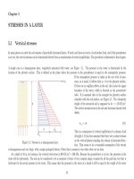
θ
h
N
W
Q
T
Figure 34.2: Passive earth pressure.
downward direction. The weight of the wedge is, as in the active case,
W =
1
2
γh
2
tan θ. (34.13)
The equations of equilibrium in x- and z-direction now are
Q − T sin θ − N cosθ = 0, (34.14)
W −N sin θ + T cos θ = 0. (34.15)
Arnold Verruijt, Soil Mechanics : 34. COULOMB 193
After elimination of T and N from the equations, and some trigonometric manipulations, the force Q is found to be
Q =
1
2
γh
2
+
1
2
γh
2
sin φ + ch cos φ
cos θ sin(θ − φ)
. (34.16)
Again this force appears to be dependent on the angle θ. The minimum value of Q occurs if the function
f(θ) = cos θ sin(θ − φ),
has its largest value. Differentiation gives
df
dθ
= cos(2θ − φ),
and
d
2
f
dθ
2
= −2 sin(2θ − φ).
It now follows that df/dθ = 0 if 2θ − φ =
1
2
π, or
df
dθ
= 0 : θ =
1
4
π +
1
2
φ. (34.17)
Then d
2
f/dθ
2
= −2, and the function f indeed has a maximum for that value of θ. That means that the horizontal force Q has a minimum.
This minimum is
θ =
1
4
π +
1
2
φ : Q =
1
2
γh
2
K
p
+ 2ch
K
p
, (34.18)
where K
p
is the passive earth pressure coefficient, defined before,
K
p
=
1 + sin φ
1 − sin φ
. (34.19)
Again, the result is in complete agreement with the value obtained in Rankine’s analysis. Coulomb’s procedure appears to lead to the maximum
(passive) earth pressure.
Coulomb’s method can easily be extended to more general cases. It is possible, for instance, that the surface of the wall is inclined with
respect to the vertical direction, and the soil surface may also be sloping. Also, the soil may carry a given surface load. For all these cases the
method can easily be extended. The general procedure is to assume a straight slip plane, consider equilibrium of the sliding wedge, and then
maximizing or m inimizing the force against the wall. Analytical, graphical and numerical methods have been developed. In the next chapter a
number of tables is presented.
Arnold Verruijt, Soil Mechanics : 34. COULOMB 194
Problems
34.1 In some textbook s the coefficients K
a
and K
p
are defined as
K
a
= tan
2
(
1
4
π −
1
2
φ), K
p
= tan
2
(
1
4
π +
1
2
φ).
Is that an error?
34.2 If K
a
= 0.273, then what is K
p
?
34.3 A ver tical wall retains a mass of dry sand, of 4 m height. The friction angle of the sand is 30
◦
, and the volumetric weight is 17 kN/m
3
. What is the
design value of the horizontal force (per meter width) on the wall, if the deformations are not important?
34.4 Investigate the sensitivity of the previous problem for the friction angle, by determining the result for a friction angle that is 10 % higher.
34.5 What should be the design value of the horizontal force if the client wishes that the wall does not deform under any circumstances?