Air Pollution Control Systems for Boiler and Incinerators Part 4 potx
Bạn đang xem bản rút gọn của tài liệu. Xem và tải ngay bản đầy đủ của tài liệu tại đây (215.37 KB, 10 trang )
TM 5-815-1/AFR 19-6
6-1
CHAPTER 6
CYCLONES AND MULTICYCLONES
6-1. Cyclone be handled and high collection efficiencies are needed
The cyclone is a widely used type of particulate collec-
tion device in which dust-laden gas enters tangentially
into a cylindrical or conical chamber and leaves
through a central opening. The resulting vortex motion
or spiraling gas flow pattern creates a strong
centrifugal force field in which dust particles, by virtue
of their inertia, separate from the carrier gas stream.
They then migrate along the cyclone walls by gas flow
and gravity and fall into a storage receiver. In a boiler
or incinerator installation this particulate is composed
of fly-ash and unburned combustibles such as wood
char. Two widely used cyclones are illustrated in figure
6-1.
6-2. Cyclone types
a. Cyclones are generally classified according to
their gas inlet design and dust discharge design, their
gas handling capacity and collection efficiency, and
their arrangement. Figure 6-2 illustrates the various
types of gas flow and dust discharge configurations
employed in cyclone units. Cyclone classification is
illustrated in table 6-1.
b. Conventional cyclone. The most commonly used
cyclone is the medium efficiency, high gas throughput
(conventional) cyclone. Typical dimensions are illus-
trated in figure 6-3. Cyclones of this type are used
primarily to collect coarse particles when collection
efficiency and space requirements are not a major con-
sideration. Collection efficiency for conventional
cyclones on 10 micron particles is generally 50 to 80
percent.
c. High efficiency cyclone. When high collection
efficiency (80-95 percent) is a primary consideration in
cyclone selection, the high efficiency single cyclone is
commonly used (See figure 6-4). A unit of this type is
usually smaller in diameter than the conventional
cyclone, providing a greater separating force for the
same inlet velocity and a shorter distance for the parti-
cle to migrate before reaching the cyclone walls. These
units may be used singly or arranged in parallel or
series as shown in figure 6-5. When arranged in paral-
lel they have the advantage of handling larger gas vol-
umes at increased efficiency for the same power con-
sumption of a conventional unit. In parallel they also
have the ability to reduce headroom space require-
ments below that of a single cyclone handling the same
gas volumes by varying the number of units in opera-
tion.
d. Multicyclones. When very large gas volumes must
a multiple of small diameter cyclones are usually
nested together to form a multicyclone. A unit of this
type consists of a large number of elements joined
together with a common inlet plenum, a common
outlet plenum, and a common dust hopper. The
multicyclone elements are usually characterized by
having a small diameter and having axial type inlet
vanes. Their performance may be hampered by poor
gas distribution to each element, fouling of the small
diameter dust outlet, and air leakage or back flow from
the dust bin into the cyclones. These problems are
offset by the advantage of the multicyclone’s increased
collection efficiency over the single high efficiency
cyclone unit. Problems can be reduced with proper
plenum and dust discharge design. A typical fractional
efficiency curve for multi-cyclones is illustrated in
figure 6-6.
e. Wet or irrigated cyclone. Cyclones may be oper-
ated wet in order to improve efficiency and prevent
wall buildup or fouling (See fig. 6-7). Efficiency is
higher for this type of operation because dust particles,
once separated, are trapped in a liquid film on the
cyclone walls and are not easily re-entrained. Water is
usually sprayed at the rate of 5 to 15 gallons per 1,000
cubic feet (ft ) of gas. Wet operation has the additional
3
advantages of reducing cyclone erosion and allowing
the hopper to be placed remote from the cyclones. If
acids or corrosive gases are handled, wet operation
may result in increased corrosion. In this case, a
corrosion resistant lining may be needed. Re-
entrainment caused by high values of tangential wall
velocity or accumulation of liquid at the dust outlet can
occur in wet operation. However, this problem can be
eliminated by proper cyclone operation. Wet operation
is not currently a common procedure for boilers and
incinerators.
6-3. Cyclone collection efficiency
a. Separation ability. The ability of a cyclone to
separate and collect particles is dependent upon the
particular cyclone design, the properties of the gas and
the dust particles, the amount of dust contained in the
gas, and the size distribution of the particles. Most
efficiency determinations are made in tests on a geo-
metrically similar prototype of a specific cyclone
design in which all of the above variables are
accurately known. When a particular design is chosen
it is usually accurate to estimate cyclone collection
efficiency based upon the cyclone manufacturer’s
TM 5-815-1/AFR 19-6
6-2
efficiency curves for handling a similar dust and gas. efficiency curve in order to determine overall cyclone
All other methods of determining cyclone efficiency collection efficiency.
are estimates and should be treated as such. (1) A particle size distribution curve shows the
b. Predicting cyclone collection efficiency. A parti- weight of the particles for a given size range
cle size distribution curve for the gas entering a cyclone in a dust sample as a percent of the total
is used in conjunction with a cyclone fractional weight of the sample. Particle size
TM 5-815-1/AFR 19-6
6-3
TM 5-815-1/AFR 19-6
6-4
TM 5-815-1/AFR 19-6
6-5
distributions are determined by gas sampling inlet ductwork and the outlet ductwork. This pressure
and generally conform to statistical drop is a result of entrance and exit losses, frictional
distributions. See figure 6-8. losses and loss of rotational kinetic energy in the
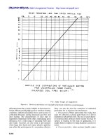
(2) A fractional cyclone efficiency curve is used exiting gas stream. Cyclone pressure drop will increase
to estimate what weight percentage of the as the square of the inlet velocity.
particles in a certain size range will be b. Cyclone energy requirements. Energy require-
collected at a specific inlet gas flow rate and ments in the form of fan horsepower are directly pro-
cyclone pressure drop. A fractional efficiency portional to the volume of gas handled and the cyclone
curve is best determined by actual cyclone resistance to gas flow. Fan energy requirements are
testing and may be obtained from the cyclone estimated at one quarter horsepower per 1000 cubic
manufacturer. A typical manufacturer’s frac- feet per minute (cfm) of actual gas volume per one
tion efficiency curve is shown on figure 6-9. inch, water gauge, pressure drop. Since cyclone
(3) Cyclone collection efficiency is determined by pressure drop is a function of gas inlet and outlet areas,
multiplying the percentage weight of particles cyclone energy requirements (for the same gas volume
in each size range (size distribution curve) by and design collection efficiency) can be minimized by
the collection efficiency corresponding to that reducing the size of the cyclone while maintaining the
size range (fractional efficiency curve), and same dimension ratios. This means adding more units
adding all weight collected as a percentage of in parallel to handle the required gas volume. The
the total weight of dust entering the cyclone. effect on theoretical cyclone efficiency of using more
6-4. Cyclone pressure drop and energy pressure drop is shown in figure 6-10. The increased
requirements collection efficiency gained by compounding cyclones
a. Pressure drop. Through any given cyclone there
will be a loss in static pressure of the gas between the
units in parallel for a given gas volume and system
in parallel can be lost if gas recirculation among
individual units is allowed to occur.
TM 5-815-1/AFR 19-6
6-6
6-5. Application other equipment or as a final cleaner to improve
a. Particulate collection. Cyclones are used as par-
ticulate collection devices when the particulate dust is
coarse, when dust concentrations are greater than 3
grains per cubic foot (gr/ft ), and when collection effi-
3
ciency is not a critical requirement. Because collection
efficiencies are low compared to other collection
equipment, cyclones are often used as pre-cleaners for
overall efficiency.
b. Pre-cleaner. Cyclones are primarily used as pre-
cleaners in solid fuel combustion systems such as
stoker fired coal burning boilers where large coarse
particles may be generated. The most common applica-
tion is to install a cyclone ahead of an electrostatic
precipitator. An installation of this type is particularly
TM 5-815-1/AFR 19-6
6-7
TM 5-815-1/AFR 19-6
6-8
TM 5-815-1/AFR 19-6
6-9
TM 5-815-1/AFR 19-6
6-10
efficient because the cyclone exhibits an increased col- They can also be used for collection of unburned
lection efficiency during high gas flow and dust loading particulate for re-injection into the furnace.
conditions, while the precipitator shows and increase in c. Fine particles. Where particularly fine sticky dust
collection efficiency during decreased gas flow and must be collected, cyclones more than 4 to 5 feet in
dust loading. The characteristics of each type of diameter do not perform well. The use of small diame-
equipment compensate for the other, maintaining good ter multicyclones produces better results but may be
efficiency over a wide range of operating flows and subject to fouling. In this type of application, it is
dust loads. Cyclones are also used as pre-cleaners usually better to employ two large diameter cyclones in
when large dust loads and coarse abrasive particles series.
may affect the performance of a secondary collector. d. Coarse particles. when cyclones handle coarse