Applied Computational Fluid Dynamics Techniques - Wiley Episode 1 Part 8 docx
Bạn đang xem bản rút gọn của tài liệu. Xem và tải ngay bản đầy đủ của tài liệu tại đây (437.37 KB, 25 trang )
SIMPLE EULER / NAVIER – STOKES SOLVERS
163
This is the same as central differencing! A stability analysis of the RHS,
ri = −
1
(ui+1 − ui−1 ),
2h
(8.15)
indicates that only every second node is coupled, allowing zero-energy or chequerboard
modes in the solution. Therefore, stabilizing terms have to be added to re-couple neighbouring
nodes.
The two most common stabilizing terms added are as follows.
1. Terms of second order: h2 ∂ 2 /∂x 2 , which result in an additional RHS term of
ui+1 − 2ui + ui−1 ,
(8.16)
which equals 4 for the (−1, 1, −1) chequerboard pattern on a uniform mesh shown in
Figure 8.1. Most TVD schemes use this type of stabilization term.
u
1
0
i-1
i
i+1
i+2
x
-1
Figure 8.1. Chequerboard mode on a uniform 1-D grid
2. Terms of fourth order: h4 ∂ 4 /∂x 4 , which result in an additional RHS term of
ui+2 − 4ui+1 + 6ui − 4ui−1 + ui−2 ,
(8.17)
which equals 16 for the (−1, 1, −1) chequerboard pattern on a uniform mesh shown
in Figure 8.1. Observe that this type of stabilization term has a much more pronounced
effect than second-order terms. Therefore, one may use much smaller constants when
adding them. The fourth-order operator can be obtained in several ways. One obvious
choice is to perform two ∇ 2 -passes over the mesh (Jameson et al. (1986), Mavriplis
and Jameson (1990)). Another option is to first obtain the gradients of u at points,
and then to approximate the third derivatives by taking a difference between first
derivatives obtained from the gradients and the first derivatives obtained directly from
the unknowns (Peraire et al. (1992a)). The implications of choosing either of these
approaches will be discussed in more depth in Chapter 10.
164
APPLIED COMPUTATIONAL FLUID DYNAMICS TECHNIQUES
8.1.1. EQUIVALENCY WITH FVM
Before going on, the GFEM using linear elements will be shown to be equivalent to the FVM.
Integration by parts in (8.8) yields
ri = −
ˆ
N i ∇ · N j F(uj ) d
ˆ
(∇N i )N j · F(uj ) d
=
+
....
(8.18)
As seen from Section 4.2.4, for linear triangles, this integral reduces to
ri =
A
(∇N i ) ·
3
ˆ
F(uj ) =
jel
1 1
· (si ni ) ·
3 2
ˆ
F(uj ),
(8.19)
jel
and in particular, for node a in Figure 8.2,
ra =
Fb + Fc
Fa
+
.
2
2
sa na
·
3
(8.20)
On the other hand,
sa na = 0,
(8.21)
surrel
which implies that when taking the sum over all surrounding elements, the first term on
the RHS of (8.20) vanishes. The remaining two terms are the same as those obtained when
performing a FVM line-integral approximation around node a.
Fb
S
n
a
a
b
F
c
c
F
a
a
Figure 8.2. Equivalency of linear GFEM and FVM
The same equivalency between the GFEM with linear elements and FVMs can also be
shown for 3-D tetrahedra.
8.2. Lax–Wendroff (Taylor–Galerkin)
All Lax–Wendroff type schemes are derived by performing a Taylor-series expansion in time
(Lax and Wendroff (1960), Donea (1984), Löhner et al. (1984))
u=
tu,t +
t2
u,tt
2
n+
.
(8.22)
SIMPLE EULER / NAVIER – STOKES SOLVERS
165
Then the original equation,
u,t = −∇ · F,
(8.23)
is used repeatedly in conjunction with the Jacobians of the fluxes A,
F=A·
u.
(8.24)
This results in
n+
t2
∇ ·A·∇ ·F
2
Linearization of the second term on the RHS via
u = − t∇ · F +
F|n+ = Fn +
A·
.
u
(8.25)
(8.26)
yields the final scheme:
1−
t2
∇ · A ⊗ A∇·
2
u = − t∇ · F +
t2
∇ · A · ∇ · F.
2
(8.27)
This timestepping scheme is then discretized in space using the GFEM. Note that the last
term in (8.27) provides a matrix dissipation (or streamline upwinding for the scalar advection
equation). This is very similar to the streamline upwind Petrov–Galerkin (SUPG) techniques
(Tezduyar and Hughes (1983), Hughes and Tezduyar (1984), Le Beau and Tezduyar (1991))
for linear/bilinear elements, except that in the latter case the multiplicative factor is not the
timestep but a mesh and flow variables dependent variable.
8.2.1. EXPEDITING THE RHS EVALUATION
The appearance of the Jacobians A makes the evaluation of the RHS tedious. Substantial
savings may be realized by developing two-step schemes that approximate the RHS without
recourse to A (Burstein (1967), Lapidus (1967), MacCormack (1969)). The simplest two-step
scheme that accomplishes this goal is given by:
Half-step: predict un+0.5
un+0.5 = u −
t
∇ · F.
2
(8.28a)
Full-step: use un+0.5
u = − t∇ · F(un+0.5 ) = − t∇ · F u −
t
∇ ·F
2
t2
∇ · A · ∇ · F(u).
(8.28b)
2
Several possibilities exist for the spatial discretization. If one chooses linear shape functions
for both half-steps (N i , N i ), a five-point stencil is obtained in one dimension. The scheme
obtained is identical to a two-step Runge–Kutta GFEM. Thus, for the steady state no damping
is present. Another possibility is to choose constant shape functions for the half-step solution
(P e , N i ). This choice recovers the original three-point stencil in one dimension, and for the
linear advection equation yields the same scheme as that given by (8.27). Observe that this
scheme has a second-order damping operator for the steady state. Thus, this second scheme
requires no additional stabilization operator for ‘mild’ problems (e.g. subsonic flows without
shocks). The difference between these schemes is shown conceptually in Figure 8.3.
= − t∇ · F(u) +
166
APPLIED COMPUTATIONAL FLUID DYNAMICS TECHNIQUES
time
t n+1
t n+0.5
tn
space
time
t n+1
t n+0.5
tn
space
Figure 8.3. Two-step schemes
8.2.2. LINEAR ELEMENTS (TRIANGLES, TETRAHEDRA)
Because of the widespread use of the latter scheme, a more detailed description of it will be
given. The spatial discretization is given by
1
- at t n+ 2 = t n +
1
2
t: u, F piecewise constant;
- at t n , t n+1 : u, F piecewise linear.
(a) First step. When written out, the first step results in the following GATHER, ADD
operations:
1 Nn n
t Nn i k
n+ 1
·
·
ui −
N F ,
(8.29a)
uel 2 =
Nn i=1
2 i=1 ,k i
where Nn denotes the number of nodes of the element.
(b) Second step. The second step involves SCATTER-ADD operations:
i
j
N N d
·
t
·
uj =
Nn
i k
VOLel · N,k Fel
n+ 1
2
,
(8.29b)
el
and results in the matrix system
Mc ·
un = rn .
The flow of information for these two steps is shown in Figure 8.4.
(8.30)
SIMPLE EULER / NAVIER – STOKES SOLVERS
(a)
167
( b)
Figure 8.4. Two-step Taylor–Galerkin scheme
8.3. Solving for the consistent mass matrix
Due to its very favourable conditioning, (8.30) is best solved iteratively as
Ml · ( un −
i+1
un ) = rn − Mc ·
i
un ,
i = 0, . . . , niter,
un = 0.
0
(8.31)
In practice, no more than three iterations are employed (niter ≤ 3).
8.4. Artificial viscosities
An observation made time and time again is that for shocks or other discontinuities the
damping provided by the stabilized GFEM or the Lax–Wendroff schemes is not sufficient.
The simulated flowfields exhibit unphysical results, with overshoots or undershoots in
pressure, density, etc. In most cases, the numerical results will eventually diverge or, to
use the more common term, ‘blow up’. Therefore, some additional artificial dissipation or
stabilization (a more elegant term for the same thing) has to be added. In a real flow, the
vicinity of a shock is controlled by the viscous effects that become large over the small width
of the shock. The shock width is typically orders of magnitude smaller than the smallest
mesh size used in current simulations. Therefore, this viscosity effect has to be scaled to the
current mesh size. At the same time, the effects of these artificial viscosity terms should only
be confined to shock or discontinuity regions. Thus, a sensing function must be provided to
locate these regions in space. These considerations lead to artificial viscosity operators of the
form
t
d=
∇(h2 f (u))∇u.
(8.32)
tl
Here f (u) denotes the sensing function and h the element size. The ratio of timestep taken
( t) to allowable timestep ( t l ) is necessary to avoid a change in solution when shifting
from local to global timesteps. Some popular artificial viscosities are listed below.
(a) Lapidus. Defined by (see Figure 8.5)
d=
where
l=
∇|v|
,
|∇|v||
t·
∂
∂u
|k ll |
,
∂l
∂l
k ll = c1 · h2 ·
∂(v · l)
.
∂l
The salient features of this type of artificial viscosity are as follows:
(8.33)
(8.34a, b)
168
APPLIED COMPUTATIONAL FLUID DYNAMICS TECHNIQUES
Shock
Shear Layer
v
1
v
2
l
v
1
v
2
l
Figure 8.5. Lapidus artificial viscosity
- it is invariant under coordinate rotation;
- it is essentially 1-D and thus fast;
- it produces the desired effects at shocks;
- k ll vanishes at shear and boundary layers;
- the identification of shocks (k ll < 0) or expansions (k ll > 0) is simple.
The Lapidus artificial viscosity (Lapidus (1967), Löhner et al. (1985a)) is most often
employed for transient simulations in conjunction with more sophisticated FCT (Löhner et al.
(1987)) or TVD schemes (Woodward and Colella (1984)) in order to add some background
damping.
(b) Pressure-based. Given by
d=
t
∇(h2 f (p))∇u.
tl
(8.35)
The salient features of this type of artificial viscosity are as follows:
- it is invariant under coordinate rotation;
- ∇ 2 may be approximated by (Ml − Mc ), yielding a fast scheme;
- because the pressure p is near constant in shear and boundary layers, f (p) should
vanish there;
- usually, the enthalpy is taken for the energy equation in u.
Many variations have been proposed for the sensing function f (p). The three more popular
ones are as follows:
(b1) Jameson–Schmidt–Turkel:
f (p) = c1
|∇h2 ∇p|
,
p
¯
(8.36)
which is very good for transonic flows (Jameson et al. (1981), Löhner et al. (1985b));
SIMPLE EULER / NAVIER – STOKES SOLVERS
169
(b2) Hassan–Morgan–Peraire:
f (p) = c2
|∇h2 ∇p|
,
|h∇p|
(8.37)
which is more suitable for hypersonic flows (Hassan et al. (1990)); and
(b3) Swanson–Turkel:
f (p) = c3
|∇h2 ∇p|
,
α|h∇p| + (1 − α)p
¯
(8.38)
which is a blend of the first two (Swanson and Turkel (1992)). Typically, α = 0.5.
8.5. Boundary conditions
No numerical scheme is complete without proper ways of imposing boundary conditions. The
Euler equations represent a hyperbolic system of PDEs. Linearization around any arbitrary
state yields a system of advection equations for so-called characteristic variables (Usab
and Murman (1983), Thomas and Salas (1985)). The proper handling of these boundary
conditions will be discussed below. The following notation will be employed:
ρ:
vn :
vt :
p:
c:
the density;
the normal velocity component at the boundary (pointing inwards);
the tangential velocity component at the boundary;
the pressure; and
the velocity of sound.
Furthermore, use will be made of the Bernoulli equation, given by the total pressure relation:
v2
γ p v2
γ p0
+
= const.,
+ 0 =
γ − 1 ρ0
2
γ −1ρ
2
and the isentropic relation
p
p0
= γ.
ργ
ρ0
(8.40)
(8.41)
Given a velocity, and assuming constant total pressure along the streamlines, the pressure and
density may be computed as
p0
γ −1 2
p
=
[v0 − v 2 ],
+
ρ
ρ0
2γ
(8.42)
and from the isentropic relation (8.41),
γ
ρ=
ρ0 p
p0 ρ
1/(γ −1)
.
(8.43)
With ρ, p is obtained again from (8.41):
p=
p0 γ
γρ .
ρ0
(8.44)
170
APPLIED COMPUTATIONAL FLUID DYNAMICS TECHNIQUES
Suppose that an explicit evaluation of the fluxes (i.e. the RHS) has been performed and
the unknowns have been updated. These predicted unknowns, that have to be corrected
at boundaries, will be denoted by ‘∗’, e.g. the predicted density as ρ∗ . A linearized
characteristics analysis can be used to correct the predicted (∗) values; performing a 1-D
analysis at the boundary, in the direction normal to it, we have, with the inward normal n (see
Figure 8.6), the following set of eigenvalues and eigenvectors:
vn
v
λ= n ,
vn + c
vn − c
ρ − p/c2
vt
W=
[vn + p/(ρc)] ,
[−vn + p/(ρc)]
(8.45)
where u denotes the average between the values at the previous timestep and the predicted
¯
state for unknown u.
n
Subsonic Inflow
Wing Wall
Subsonic
Outflow
n
Ma<1
n
Subsonic
Outflow
Subsonic Inflow
n
Engine Wall
Figure 8.6. Boundary conditions for wing
One is now in a position to correct the predicted variables depending on the Mach number
of the flow. The possible states are: supersonic inflow, subsonic inflow, subsonic outflow and
supersonic outflow. Let us consider them in turn.
(a) Supersonic inflow. In this case, there should be no change in the variables, as no
information can propagate upstream. Therefore, the variables are reset to the values at the
beginning of the timestep. Thus, the predicted values are discarded in this case.
(b) Subsonic inflow. The incoming characteristics are λ1−3 , while the outgoing characteristic
is λ4 . The values for the variables W1 , W2 , W3 , corresponding to the incoming characteristics,
SIMPLE EULER / NAVIER – STOKES SOLVERS
171
are taken from the ‘state at infinity’, and W4 is taken from the predicted state. This results in
ρ − p/c2 = ρ∞ − p∞ /c2 ,
vt = vt ∞ ,
vn + p/(ρc) = vn∞ + p∞ /(ρc),
(8.46)
−vn + p/(ρc) = −vn∗ + p∗ /(ρc)
or, after elimination,
vt = vt ∞ ;
p = 0.5[p∞ + p∗ + ρc(vn∞ − vn∗ )]
→ ρ = ρ∞ + (p − p∞ )/c2 ;
vn = vn∞ + (p∞ − p)/(ρc).
(8.47)
For the case of total pressure one first computes, from the predicted velocity v∗ the
corresponding pressures and densities. These pressures and densities are then taken as the
new ‘state at infinity’. The resulting equations are
vt = vt ∞ ;
→ p = 0.5(p∞ + p∗ );
vn = vn∗
→ ρ = ρ∞ + (p − p∞ )/c2 .
(8.48)
(c) Subsonic outflow. The incoming characteristics are λ3 , while the outgoing characteristics
are λ1,2,4 . The value for the variable W3 , corresponding to the incoming characteristic, is
taken from the ‘state at infinity’, and W1 , W2 , W4 are taken from the predicted state. The
resulting equations are
ρ − p/c2 = ρ∗ − p∗ /c2 ,
vt = vt ∗ ,
vn + p/(ρc) = vn∞ + p∞ /(ρc),
−vn + p/(ρc) = −vn∗ + p∗ /(ρc).
(8.49)
There are several possibilities, depending on what has to be specified.
(c1) Prescribed state vn∞ , p∞ :
vt = vt ∗ ;
p = 0.5[p∞ + p∗ + ρc(vn∞ − vn∗ )]
→ ρ = ρ∗ + (p − p∗ )/c2 ;
vn = vn∞ + (p∞ − p)/(ρc).
(8.50)
(c2) Prescribed pressure p∞ :
vt = vt ∗ ;
p = p∞
→ ρ = ρ∗ + (p∞ − p∗ )/c ;
vn = vn∗ + (p∞ − p∗ )/(ρc).
2
(8.51)
(c3) Prescribed Mach number m∞ :
vt = vt ∗ ;
vn = −c∗ m∞
→ p = p∗ + ρ∗ c∗ (vn − vn∗ );
→ ρ = ρ∗ + (p − p∗ )/c2 .
(8.52)
172
APPLIED COMPUTATIONAL FLUID DYNAMICS TECHNIQUES
(c4) Prescribed mass flux (ρvn )∞ :
vt = vt ∗ ; p = p∗ + c∗ ((ρvn )∞ − ρ∗ vn∗ )
→ ρ = ρ∗ + (p − p∗ )/c2 ; → vn = (ρvn )∞ /ρ.
(8.53)
(d) Supersonic outflow. In this case, no information can propagate into the computational
domain from the exterior. Therefore, the predicted variables are left unchanged.
(e) Solid walls. For walls, the only boundary condition one can impose is the no-penetration
condition, taking into consideration the wall velocity w. The predicted momentum at the
surface ρv∗ is decomposed as
ρv∗ =
[ρ(w + αt + βn)],
(8.54)
where t and n are the tangential and normal vectors, respectively. The desired momentum at
the new timestep should, however, have no normal velocity component (β = 0) and it has the
form
ρvn+1 = [ρ(w + αt)].
(8.55)
Combining the last two equations, we obtain the two following cases.
(e1) Given t:
ρvn+1 = ρw + [( ρv∗ − ρw) · t] · t.
(8.56)
ρvn+1 = ρv∗ − [( ρv∗ − ρw) · n] · n.
(8.57)
(e2) Given n:
(f) Porous walls. For porous walls, the velocity normal to the wall is given as a function of
the difference p = pi − po between the inner and outer pressures. This function is obtained
from measurements. A typical way to model the behaviour is via a linear–linear model of the
form
p
,
p1
pb
p − pb
| p| ≥ p2 : vn = c1
+ c2
,
p1
p1
| p| < p2 : vn = c1
(8.58)
(8.59)
where c1 , c2 , p1 , p2 are empirically determined constants.
8.6. Viscous fluxes
After schemes that are suitable for the Euler equations have been described, the proper
discretization of the viscous fluxes must be considered. The RHS for the Galerkin weighted
residual statement is of the form
ri =
N k Fv d .
(8.60)
As the viscous and thermal fluxes are themselves functions of the flow variables that involve
derivatives (equations (8.2) and (8.4)), one must either recover them at points or at the element
level. The first possibility results in two passes over the mesh as follows.
SIMPLE EULER / NAVIER – STOKES SOLVERS
173
(a1) Evaluation of viscous fluxes at points, e.g.,
N k N l σij d
=
Nk µ
∂vj
∂vi
+
∂xj
∂xi
+λ
∂vk
δij d ,
∂xk
(8.61)
which may be recast as
Mc σij =
Nk µ
∂N l
∂N l
∂N l
vi |l +
ˆ
vj |l + λ
ˆ
δij vk |l d .
ˆ
∂xj
∂xi
∂xk
(8.62)
(a2) Given the stresses σij at the nodes, evaluation of viscous flux derivatives to form the
RHS:
∂σij
∂N l
RHSik = N k
d = Nk
d σij .
(8.63)
∂xj
∂xj
The second possibility, which is more natural for FEMs, results in
RHSik =
Nk
∂σij
d
∂xj
=−
∂N k
σij d
∂xj
+
nj N k σij d .
(8.64)
Here nj denotes the component of the surface normal vector in the j th direction. Inserting
the appropriate expressions for the stresses results in
∂N l
∂N k
∂N l
∂N l
µ
vi |l +
ˆ
vj |l + λ
ˆ
δij vk |l d
ˆ
∂xj
∂xj
∂xi
∂xk
RHSik = −
+
nj N k µ
∂N l
∂N l
∂N l
vi |l +
ˆ
vj |l + λ
ˆ
δij vk |l d .
ˆ
∂xj
∂xi
∂xk
(8.65)
If one evaluates these expressions within a simple 1-D context, it can be observed that the
first possibility results in a five-point stencil, whereas the second possibility results in a
more compact stencil of only three points. The second possibility is clearly better suited
for element-based codes, as it represents the natural, self-adjoint discretization of the viscous
stresses and thermal fluxes. For edge-based solvers the additional storage required for all the
i, j components of the tensor of second derivatives would more than double the memory
requirements. For this reason, most edge-based solvers use the first form when evaluating the
viscous terms.
A third way to evaluate the viscous fluxes is found by separating the terms forming
Laplacian operators from the rest of the viscous fluxes. For the momentum equations this
results in
∂σij
∂vj
∂vi
∂
∂
∂vk
µ
+
µ
(8.66)
=
+λ
δij ,
∂xj
∂xj
∂xj
∂xj
∂xi
∂xk
and for the energy equation
∂
∂xj
vl σlj + k∂T
∂xj
=
∂
∂xj
∂T
µ ∂vl vl
+k
2 ∂xj
∂xj
+
∂vj
∂
∂vk
µvl
+λ
δlj .
∂xj
∂xl
∂xk
(8.67)
Unless pronounced compressibility effects are present, the dominant terms are the ones that
result in purely Laplacian operators. These are then treated in the usual FEM way by storing
only one additional entry (for the Laplacian) per edge. The remainder terms are treated by
taking first derivatives of gradients. For most solvers the gradients are required for limiting,
so there is almost no extra cost involved.
9 FLUX-CORRECTED TRANSPORT
SCHEMES
Although flux-corrected transport (FCT) schemes have not enjoyed the popularity of total
variation diminishing (TVD) schemes in the steady-state CFD community, they are included
here for the following reasons.
(a) FCT schemes were the first to introduce the concept of limiters (Boris and Book
(1973, 1976), Book and Boris (1975)), and particularly for didactic purposes it never
hurts to go back to the source.
(b) FCT schemes are used almost exclusively in the unsteady CFD and plasma physics
communities.
(c) Unlike TVD schemes, FCT limiting is based directly on the unknowns chosen. This
makes FCT ideally suited to introduce the concept of nonlinear schemes and limiting.
FCT schemes were developed from the observation that linear schemes, however good,
perform poorly for transient problems with steep gradients. For these linear schemes, the
choice is between high-order, oscillatory, ‘noisy’ solutions, or low-order, overdiffusive,
‘smooth’ solutions. Godunov’s theorem (Godunov (1959)) states this same observation as:
Theorem. (Godunov) No linear scheme of order greater than 1 will yield monotonic (wigglefree, ripple-free) solutions.
The way to circumvent this stringent theorem is to develop nonlinear schemes. This is
most easily accomplished by mixing a high-order and a low-order scheme. The process of
combining these two schemes in a rational way is called limiting.
Any high-order scheme used to advance the solution either in time or between iterations
towards the steady state may be written as
un+1 = un +
uh = un +
ul + ( uh −
ul ) = ul + ( uh −
ul ).
(9.1)
Here uh and ul denote the increments obtained by the high- and low-order scheme,
respectively, and ul is the monotone, ripple-free solution at time t = t n+1 of the low-order
scheme. The idea behind FCT is to limit the second term on the RHS of (9.1),
un+1 = ul + lim( uh −
ul ),
(9.2)
in such a way that no new over/undershoots are created. It is at this point that a further
constraint, given by the original conservation law itself, must be taken into account: strict
conservation on the discrete level should be maintained. This means that the limiting process
will have to be carried out wherever RHS contributions are computed: for element-based
schemes at the element level, for edge-based schemes at the edges.
Applied Computational Fluid Dynamics Techniques: An Introduction Based on Finite Element Methods, Second Edition.
Rainald Löhner © 2008 John Wiley & Sons, Ltd. ISBN: 978-0-470-51907-3
176
APPLIED COMPUTATIONAL FLUID DYNAMICS TECHNIQUES
9.1. Algorithmic implementation
The concept of FCT can now be translated into a numerical scheme. The description is given
for element-based schemes. For edge-based schemes, replace ‘element’ by ‘edge’ in what
follows. For finite volume schemes, one may replace ‘element’ by ‘cell’. FCT consists of the
following six algorithmic steps:
1. Compute LEC: the element contributions from some low-order scheme guaranteed to
give monotonic results for the problem at hand;
2. Compute HEC: the element contributions given by some high-order scheme;
3. Define the anti-diffusive element contributions:
AEC = HEC − LEC;
(9.3)
4. Compute the updated low-order solution ul :
ul = u n +
i
i
LEC,
i = 1, . . . , npoin;
(9.4)
el
5. Limit or correct the AEC so that un+1 as computed in step 6 is free of extrema not also
found in ul or un :
(9.5)
AECc = Cel · AEC, 0 ≤ Cel ≤ 1;
6. Apply the limited AEC:
un+1 = ul +
i
i
AECc .
(9.6)
el
9.1.1. THE LIMITING PROCEDURE
Obviously, the whole approach depends critically on step 5 above. If we consider an isolated
point surrounded by elements, the task of the limiting procedure is to insure that the
increments or decrements due to the anti-diffusive element contributions AEC do not exceed
a prescribed tolerance (see Figure 9.1).
In the most general case, the contributions to a point will be a mix of positive and
negative contributions. Given that the AECs will be limited, i.e. multiplied by a number
0 ≤ Cel ≤ 1, it may happen that after limiting all positive or negative contributions vanish.
The largest increment (decrement) will occur when only the positive (negative) contributions
are considered. For this reason, we must consider what happens if only positive or only
negative contributions are added to a point. The comparison of the allowable increments and
decrements with these all-positive and all-negative contributions then yields the maximum
allowable percentage of the AECs that may be added or subtracted to a point. On the other
hand, an element may contribute to a number of nodes and, in order to maintain strict
conservation, the limiting must be performed for all the element node contributions in the
same way. Therefore, a comparison for all the nodes of an element is performed, and the
smallest of the evaluated percentages that applies is retained.
Define the following quantities:
FLUX - CORRECTED TRANSPORT SCHEMES
177
un
u
n+1
allowable range for u i
ul
i
x
Figure 9.1. Limiting procedure
Pi± : the sum of all positive (negative) element contributions to node i,
max
(0, AECel );
min
Pi± =
el
(9.7)
Q± : the maximum (minimum) increment node i is allowed to achieve in step 6 above,
i
max
Q± = uimin − ul .
i
(9.8)
The ratio of positive and negative contributions that ensure monotonicity is then given by
R ± :=
min(1, Q± /P ± ) P + > 0 > P − ,
0
otherwise.
(9.9)
For the elements, the final value taken is the most conservative:
Cel = min(element nodes)
R+
R−
if AEC > 0,
if AEC < 0.
(9.10)
max
The allowed value uimin is taken between each point and its nearest-neighbours. For elementbased schemes, it may be obtained in three steps as follows:
(a) maximum (minimum) nodal unknowns of un and ul :
u∗ =
i
max
(ul , un );
i
i
min
(9.11)
(b) maximum (minimum) nodal value of element:
u∗ =
el
max
(u∗ , u∗ , . . . , u∗ );
A
B
C
min
(9.12)
178
APPLIED COMPUTATIONAL FLUID DYNAMICS TECHNIQUES
(c) maximum (minimum) unknowns of all elements surrounding node i:
max
uimin =
max
(u∗ , u∗ , . . . , u∗ ).
m
1
2
min
(9.13)
max
A number of variations are possible for uimin . For example, the so-called ‘clipping limiter’ is
obtained by setting u∗ = max ul in (a), i.e. by not looking back to the solution at the previous
i
min i
timestep or iteration, but simply comparing nearest-neighbour values at the new timestep or
iteration for the low-order scheme. As remarked before, the limiting is based solely on the
unknowns u, not on a ratio of differences as in most TVD schemes.
9.2. Steepening
The anti-diffusive step was designed to steepen the low-order solution obtained at the new
timestep or iteration. In some cases, particularly for high-order schemes of order greater than
two, the anti-diffusive step can flatten the profile of the solution even further, or lead to an
increase of wiggles and noise. This is the case even though the solution remains within its
allowed limits. A situation where this is the case can be seen from Figure 9.2.
AEC
x
u
un
ul
un+1 ( = 0)
un+1 ( =-1)
x
Figure 9.2. Steepener for FCT
This type of behaviour can be avoided if the anti-diffusive flux is either set to zero or
reversed. A simple way to decide when to reverse the anti-diffusive fluxes is to compute the
scalar product of the low-order solution at the new timestep or iteration and the anti-diffusive
element contributions:
∇ul · AEC < 0 ⇒ AEC = −α · AEC,
(9.14)
with 0 < α < 1. Values of α greater than unity lead to steepening. This can be beneficial
in some cases, but is highly dangerous, as it can lead to unphysical solutions (e.g. spurious
contact discontinuities) in complex applications.
FLUX - CORRECTED TRANSPORT SCHEMES
179
9.3. FCT for Taylor–Galerkin schemes
For the explicit Taylor–Galerkin schemes, FCT takes a particularly simple form. We have:
- high-order: consistent mass Taylor–Galerkin,
Mc ·
uh = r ⇒ Ml ·
uh = r + (Ml − Mc ) ·
uh ;
(9.15a)
- low-order: lumped mass Taylor–Galerkin + diffusion,
Ml ·
ul = r + d = r − cτ (Ml − Mc ) · u,
(9.15b)
where cτ denotes a diffusion coefficient.
Thus
AEC = [(Ml − Mc ) · (cτ u +
uh )]el ,
(9.16)
implying that no physical flux terms are left in AEC. This is typical of FCT schemes,
and reflects the fact that monotonicity may be imposed without knowledge of the physics
described by the fluxes. This separation of numerics and physics has several advantages,
among them speed and generality. The low-order solution will be monotone for a diffusion
coefficient cτ = 1. For cases where a large variation of possible timesteps is encountered
throughout the mesh, the allowable diffusion factor may be much lower. The ‘optimal’ choice
(in the sense of least diffusive yet monotone low-order scheme) is to take cτ = t g / t l ,
where t g is the global timestep chosen (i.e. the minimum over all elements) and t l the
allowable local timestep ( t l ≥ t g ).
9.4. Iterative limiting
Given that the anti-diffusive element contributions surrounding a point can have different
signs, and that a ‘most conservative’ compromise has to be reached for positive and negative
contributions, the remaining (i.e. not yet added) anti-diffusive element contributions may
still be added to the new solution without violating monotonicity constraints. This may be
achieved by the following iterative limiting procedure:
For iterations j = 1, k:
- perform limiting procedure,
un+1 = ul +
Cel · AEC;
el
- update remaining anti-diffusive element contributions,
AEC ← (1 − Cel )AEC;
- re-define the low-order solution at t n+1 ,
ul = un+1 .
Experience indicates that, for explicit schemes, the improvements obtained by this iterative
limiting procedure are modest. However, for implicit schemes, the gains are considerable
and well worth the extra computational effort (Kuzmin (2001), Kuzmin and Turek (2002),
Kuzmin et al. (2003, 2005)).
180
APPLIED COMPUTATIONAL FLUID DYNAMICS TECHNIQUES
9.5. Limiting for systems of equations
The results available in the literature (Boris and Book (1973), Book and Boris (1975), Boris
and Book (1976), Zalesak (1979), Parrott and Christie (1986), Löhner et al. (1987, 1988),
Zalesak and Löhner (1989)) indicate that with FCT results of excellent quality can be
obtained for a single PDE, e.g. the scalar advection equation. However, in the attempt to
extend the limiting process to systems of PDEs no immediately obvious or natural limiting
procedure becomes apparent. Obviously, for 1-D problems one could advect each simple
wave system separately, and then assemble the solution at the new timestep. However, for
multi-dimensional problems such a splitting is not possible, as the acoustic waves are circular
in nature. FDM–FCT codes used for production runs (Fry and Book (1983), Fyfe et al.
(1985)) have so far limited each equation separately, invoking operator-splitting arguments.
This approach does not always give very good results, as may be seen from Sod’s (1978)
comparison of schemes for the Riemann problem, and has been a point of continuing
criticism by those who prefer to use the more costly Riemann-solver-based, essentially
1-D TVD schemes (van Leer (1974), Roe (1981), Osher and Solomon (1982), Harten (1983),
Sweby (1984), Colella (1990), Woodward and Colella (1984)). An attractive alternative is to
introduce ‘system character’ for the limiter by combining the limiters for all equations of the
system. Many variations are possible and can be implemented, giving different performance
for different problems. Some of the possibilities are listed here, with comments where
empirical experience is available.
(a) Independent treatment of each equation as in operator-split FCT. This is the least diffusive
method, tending to produce an excessive amount of ripples in the non-conserved quantities
(and ultimately also in the conserved quantities).
(b) Use of the same limiter (Cel ) for all equations. This produces much better results,
seemingly because the phase errors for all equations are ‘synchronized’. This was also
observed by Harten and Zwaas (1972) and Zhmakin and Fursenko (1981) for a class of
schemes very similar to FCT. We mention the following possibilities.
(i) Use of a certain variable as ‘indicator variable’ (e.g. density, pressure, entropy).
(ii) Use of the minimum of the limiters obtained for the density and the energy (Cel =
min(Cel (ρ), Cel (ρe))): this produces acceptable results, although some undershoots
for very strong shocks are present. This option is currently the preferred choice for
strongly unsteady flows characterized by propagating and/or interacting shock waves.
(iii) Use of the minimum of the limiters obtained for the density and the pressure (Cel =
min(Cel (ρ), Cel (p))): this again produces acceptable results, particularly for steadystate problems.
9.5.1. LIMITING ANY SET OF QUANTITIES
A general algorithm to limit any set of quantities may be formulated as follows:
- define a new set of (non-conservative) variables u ;
- transform u, ul → u , u l and see how much u can change at each point ⇒
u |max ;
min
FLUX - CORRECTED TRANSPORT SCHEMES
181
- define a mean value of ul in the elements and evaluate
u = A(ul ) ·
- limit the transformed increments
u;
u ⇒ Cel ⇒
u = lim( u );
(9.17)
- transform back the variables and add
u∗ = A−1 (ul ) ·
u = A−1 (ul ) · Cel · A(ul ) ·
u.
(9.18)
Excellent results using limiting based on characteristic variables have been reported by
Zalesak (2005) (see also Kuzmin et al. (2003, 2005)).
9.6. Examples
9.6.1. SHOCK TUBE
This is a classic example, which was used repeatedly to compare different Euler solvers
(Sod (1978)). Initially, a membrane separates two fluid states given by ρ1 = 1.0, v1 = 0.0,
p1 = 1.0 and ρ2 = 0.1, v2 = 0.0, p2 = 0.1. The membrane ruptures, giving rise to a shock,
a contact discontinuity and a rarefaction wave. The results were obtained for an FCT run
with limiter synchronization on the density and energy. Figure 9.3 shows the surface mesh
and the surface contours of the density. A line cut through the 3-D mesh is compared to the
exact solution in Figure 9.4. Note that the number of points appearing here corresponds to
the faces of the tetrahedra being cut, i.e., it is two to three times the number of actual points.
One can see that the shock and contact discontinuities are captured over two or four elements,
respectively.
Contact Discontinuity
Shock
Figure 9.3. Shock tube: surface mesh and density
182
APPLIED COMPUTATIONAL FLUID DYNAMICS TECHNIQUES
1.1
1.2
Exact
FEFLO
1
Exact
FEFLO
1
0.9
0.8
0.7
VELOCITY
DENSITY
0.8
0.6
0.5
0.6
0.4
0.4
0.2
0.3
0.2
0
0.1
0
0
2
4
6
8
-0.2
10
0
2
4
X-COORDINATE
6
8
10
X-COORDINATE
1.1
Exact
FEFLO
1
0.9
PRESSURE
0.8
0.7
0.6
0.5
0.4
0.3
0.2
0.1
0
0
2
4
6
8
10
X-COORDINATE
Figure 9.4. Shock tube: comparison to exact values
9.6.2. SHOCK DIFFRACTION OVER A WALL
The second example shown is typical of some of the large-scale blast simulations carried
out with FCT schemes over the last decade (Baum and Löhner (1991), Sivier et al. (1992),
Baum et al. (1993, 1995), Baum and Löhner (1994), Löhner et al. (1999)), and is taken from
Rice et al. (2000). The outline of the domain is shown in Figure 9.5. Surface pressures for
an axisymmetric and 3-D run, together with a comparison to experimental photographs are
given in Figures 9.6 and 9.7. The comparison to experimental results at different stations is
shown in Figure 9.8. As one can see, FCT schemes yield excellent results for this class of
problem.
Pressure Gages
Hm
HoB
Wg
W
Hg
L2
L3
Figure 9.5. Shock diffraction over a wall
Lg
FLUX - CORRECTED TRANSPORT SCHEMES
183
Figure 9.6. Results at time t = 146 µs
Figure 9.7. Results at time t = 327 µs
9.7. Summary
The notion of limiting was introduced by reviewing FCT schemes. As seen above, these
schemes do not require gradient evaluations for the limiting procedure, and in some instances
184
APPLIED COMPUTATIONAL FLUID DYNAMICS TECHNIQUES
2.5
2
3D Simulation
2D Simulation
Experiment
Pressure (bar)
1.5
1
0.5
0
–0.5
0
0.00005
0.0001
0.00015
0.0002
0.00025
0.0003
0.00035
0.0004
Time (s)
5.5
4.5
3D Simulation
2D Simulation
Experiment
Pressure (bar)
3.5
2.5
1.5
0.5
–0.5
0
0.00005
0.0001
0.00015
0.0002
0.00025
0.0003
0.00035
0.0004
Time (s)
5.5
4.5
3D Simulation
2D Simulation
Experiment
Pressure (bar)
3.5
2.5
1.5
0.5
–0.5
0
0.00005
0.0001
0.00015
0.0002
0.00025
0.0003
0.00035
0.0004
Time (s)
Figure 9.8. Comparison to experimental values
avoid the recalculation of fluxes while limiting. This makes them extremely fast as compared
to TVD schemes. Due to their generality and ease of extension to other physical problems
that require monotonicity preserving schemes, FCT has been used extensively in many fields,
among them simulation of shock propagation (Fyfe et al. (1985), Löhner et al. (1987, 1988),
FLUX - CORRECTED TRANSPORT SCHEMES
185
Baum and Löhner (1991), Sivier et al. (1992), Baum et al. (1993, 1995), Baum and Löhner
(1994), Löhner et al. (1999)), detonation and flame propagation (Patnaik et al. (1987, 1989),
magnetohydrodynamics (Scannapieco and Ossakow (1976)) and plasma physics. Tests have
shown that FCT schemes compare very well, or in some cases are superior, to standard
TVD schemes (Zalesak and Löhner (1989), Luo et al. (1993)) or even spectral schemes
(deFainchtein et al. (1995)). This is surprising, considering that no detailed wave analysis
is invoked during the limiting process.
10 EDGE-BASED COMPRESSIBLE
FLOW SOLVERS
Consider the typical formation of a RHS using a finite element approximation with shape
functions N i . The resulting integrals to be evaluated are given by
ri =
N i r(u) d
=
N i r(N j uj ) d
el .
(10.1)
el
These integrals operate on two sets of data:
(a) point data, for ri , ui ; and
(b) element data, for volumes, shape functions, etc.
The flow of information is as follows:
1. GATHER point information into the element (e.g. ui );
2. operate on element data to evaluate the integral in (10.1); and
3. SCATTER-ADD element RHS data to point data to obtain ri .
For many simple flow solvers the effort in step 2 may be minor compared to the cost of
indirect addressing operations in steps 1 and 3. A way to reduce the indirect addressing
overhead for low-order elements is to change the element-based data structure to an edgebased data structure. This eliminates certain redundancies of information in the elementbased data structure. To see this more clearly, consider the formation of the RHS for the
Laplacian operator on a typical triangulation. Equation (10.1) may be recast as
ri = K ij uj =
Kel uel =
el
rel .
(10.1a)
el
This immediately opens three possibilities:
- obtain first the global matrix K ij and store it in some optimal way (using so-called
sparse storage techniques);
- perform a loop over elements, obtaining rel and adding to r; and
- obtain the off-diagonal coefficients K ij , i = j , perform a loop over edges i, j , obtaining
rij and adding to r.
Applied Computational Fluid Dynamics Techniques: An Introduction Based on Finite Element Methods, Second Edition.
Rainald Löhner © 2008 John Wiley & Sons, Ltd. ISBN: 978-0-470-51907-3
188
APPLIED COMPUTATIONAL FLUID DYNAMICS TECHNIQUES
The most economic choice will depend on the number of times the RHS needs to be evaluated,
how often the mesh changes, available storage, etc. The indirect addressing overhead incurred
when performing a RHS evaluation for the Laplacian using linear elements, as well as
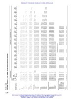
the associated FLOPS, are given in Table 10.1. Recall that for a typical mesh of triangles
nelem=2*npoin, nedge=3*npoin, npsup=6*npoin, whereas for a typical mesh of
tetrahedra nelem=5.5*npoin, nedge=7*npoin, npsup=14*npoin.
Table 10.1. (a) Laplacian: Gather/Scatter overhead for linear elements. (b) FLOPS overhead:
Laplacian/linear elements
Element-Based
Edge-Based
Sparse
3*3*nelem=18*npoin
3*4*nelem=66*npoin
3*2*nedge=18*npoin
3*2*nedge=42*npoin
6*npoin
14*npoin
3*6*nelem= 36*npoin
4*8*nelem=176*npoin
4*nedge=12*npoin
4*nedge=28*npoin
12*npoin
28*npoin
(a)
2-D
3-D
(b)
2-D
3-D
The indirect addressing overhead incurred when performing a RHS evaluation for the
Galerkin approximation to the advective fluxes and the associated FLOPS are given in
Table 10.2.
Table 10.2. (a) Gather/Scatter overhead for linear elements. (b) FLOPS overhead: Galerkin fluxes for
linear elements
Element-Based
Edge-Based
2*3*nelem=12*npoin
2*4*nelem=44*npoin
2*2*nedge=12*npoin
2*2*nedge=28*npoin
(a)
2-D
3-D
(b)
3-D
22*nelem=121*npoin
7*nedge=49*npoin
As one can see, a considerable reduction of indirect addressing operations and FLOPS has
been achieved by going to an edge-based data structure. Given their importance in generalpurpose CFD codes, the present chapter is devoted to edge-based solvers. Starting from the
by now familiar element integrals obtained for Galerkin weighted residual approximations,
the resulting edge-based expressions are derived. Thereafter, a brief taxonomy of possible
solvers is given.
10.1. The Laplacian operator
The geometrical expressions required when going from an element-based data structure to
an edge-based data structure will now be derived. For simplicity and clarity we start with the
Laplacian operator. The RHS in the domain is given by
ri = −
∇N i · ∇N j d
∇N i · ∇N j d
uj = −
ˆ
el
uj .
ˆ
(10.2)
EDGE - BASED COMPRESSIBLE FLOW SOLVERS
189
This integral can be split into those shape functions that are the same as N i and those that are
different (j = i):
∇N i · ∇N j d
ri = −
j =i
∇N i · ∇N i d
uj −
ˆ
el
ui .
ˆ
(10.3)
el
The conservation property of the shape functions
i
N,k = −
j
j =i
(10.4)
N,k ,
allows (10.3) to be re-written as
∇N i · ∇N j d
ri = −
j =i
∇N i ·
uj +
ˆ
el
el
∇N j d
ui ,
ˆ
(10.5)
j =i
or, after interchange of the double sums,
r i = k ij (ui − uj ),
ˆ
ˆ
∇N i · ∇N j d ,
k ij =
j = i.
(10.6)
el
One may observe that:
- from a change in indices (ij versus ji) we obtain k ji = k ij ; this is expected from the
symmetry of the Laplacian operator;
- the edge and its sense of direction have to be defined; this is accomplished by
- a connectivity array that stores the points of an edge
inpoed(1:2,nedge):= ip1, ip2,
and
- taking ip1 < ip2 to define the orientation;
- to build the stiffness coefficients k ij we require the edges of an element, i.e. a list of
the form inedel(nedel,nelem):= ied1,ied2,... . The rapid construction
of both inpoed and inedel have been described in Chapter 2.
A typical edge-based evaluation of the Laplacian RHS would look like the following:
rhspo(1:npoin)=0
! Set points-RHS to zero
do iedge=1,nedge
! Loop over the edges
ipoi1=inpoed(1,iedge)
! 1st point of edge
ipoi2=inpoed(2,iedge)
! 2nd point of edge
! Evaluate the edge-RHS
redge=cedge(iedge)*(unkno(ipoi2)-unkno(ipoi1)
rhspo(ipoi1)=rhspo(ipoi1)-redge
! Subtract from ipoi1
rhspo(ipoi2)=rhspo(ipoi2)+redge
! Add to ipoi2
enddo
The conservation law expressed by the Laplacian as ∇ · ∇u = 0 is reflected on each edge:
whatever is added to a point is subtracted from another. The flow of information and the
sequence of operations performed in the loop are shown in Figure 10.1.