Electric Machinery Fundamentals (Solutions Manual) Part 4 ppsx
Bạn đang xem bản rút gọn của tài liệu. Xem và tải ngay bản đầy đủ của tài liệu tại đây (140.46 KB, 10 trang )
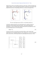
E
A
2825
10.9
=
V
°
Problems 5-11
to
5-21
refer to a two-pole Y-connected synchronous generator rated at 470 kVA, 480 V, 60 Hz,
and 0.85 PF lagging. Its armature resistance
R
A
is 0.016
&
.
The core
losses of this
generator
at rated
conditions
are
7
kW,
and the friction and windage losses are 8 kW.
The open-circuit and short-circuit characteristics are
shown in Figure P5-2.
127
Note:
An electronic version of the saturated open circuit
characteristic can
be foun
in file
p52_occ.dat
,
and
an
electronic version of the air-gap characteristi
can
be
found
in
file
p52_ag_occ.dat
.
These
files
can
be
used
wit
MATLAB programs. Column 1
contains field current in
amps, and
column
contains
open-circuit
terminal
voltage in volts. An electronic version of th
short circuit
characteristic can
be found in file
p52_scc.dat
. Column
contains field current in amps, and
column
2 contains short-circuit
termina
current in amps.
5-11.
(a)
What is
the
saturated synchronous reactance of this generator at the rated
conditions?
(b)
What is the
unsaturated synchronous reactance
of
this generator?
(c)
Plot the saturated synchronous reactance
of
this
generator as
a
function of load.
S
OLUTION
(a)
The rated armature current for this generator is
S
I
I
=
=
47
=
0 kVA
565 A
=
3
3
(
)
480
V
A
L
T
V
The
field
current
required to produce this much
short-circuit current may
be read from the SCC.
It is
0.534
A
3
.
The open circuit voltage at 0.532 A is
880
V
4
, so the open-circuit phase voltage (=
508 V.
The approximate
saturated synchronous reactance
X
S
is
E
A
) is
880/
3
=
3
If
you have MATLAB available,
you can use the file
p52_scc.dat
and
the
interp1
function to look up
this
value as shown below.
Note that column 1 of
p52_scc
contains field
current,
and column 2 contains short-circuit
terminal current.
load p52_scc.dat
if = interp1(p52_scc(:,2),p52_scc(:,1),565)
if =
128
S
X
508 V
0.899
=
=
&
565 A
(b)
The unsaturated synchronous reactance
X
Su
is the ratio of the air-gap line to the SCC. This is a
straight
line, so we can determine its value by comparing
the
ratio of the air-gap voltage to the
short-circuit
current at any
given field
current. For example,
at
SCC
is 532 A.
I
F
= 0.50
A, the air-gap
line voltage is 1040
V, and
the
X
Su
(
)
1040 V
/
3
1.13
=
=
&
532 A
(c)
This
task
can best
be performed with MATLAB. The open-circuit characteristic is available in a file
called
p52_occ.dat
, and the short-circuit characteristic is available
in
a
file
called
p52_scc.dat
.
Each
of
these
files
are
organized
in two
columns, where the first column is field current and the second
column
is
either
open-circuit
terminal voltage or short-circuit current. A program to read these files and
calculate and
plot
X
S
is
shown
below.
% M-file: prob5_11c.m
%
M-file to calculate and
plot the
saturated
% synchronous reactance of a synchronous
% generator.
% Load the open-circuit characteristic.
It
is
in
% two
columns,
with the first column
being field
% current and the second
column being terminal
% voltage.
load p52.occ;
if_occ =
p52(:,1);
vt_occ =
p52(:,2);
% Load the short-circuit
characteristic. It is in
% two
columns,
with the first column
being field
% current and the second
column being line current
% (= armature current)
load p52.scc;
if_scc =
p52(:,1);
ia_scc =
p52(:,2);
% Calculate
Xs
if
= 0.001:0.02:1;
% Current steps
vt
= interp1(if_occ,vt_occ,If); % Terminal
voltage
ia
= interp1(if_scc,ia_scc,If); % Current
Xs =
(vt ./ sqrt(3))
./
ia;
0.534
4
If
you have MATLAB available,
you can use the file
p52_occ.dat
and
the
interp1
function to look up
this
value as shown below.
Note that column 1 of
p52_occ
contains field
current,
and column 2 contains open-circuit
terminal voltage.
load p52_occ.dat
vt = interp1(p52_occ(:,1),p52_occ(:,2),0.534)
vt =
880.400
129
% Plot the synchronous reactance
figure(1)
plot(If,Xs,'LineWidth',2.0);
title
('\bfSaturated Synchronous Reactance \itX_{s} \rm');
xlabel ('\bfField Current (A)');
ylabel ('\bf\itX_{s} \rm\bf(\Omega)');
grid on;
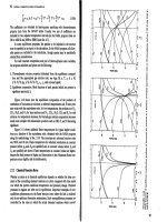
The
resulting plot is:
5-12.
(a)
What
are
the
rated
current and internal generated voltage of this generator?
(b)
What field current
does this
generator
require to operate
at the rated voltage,
current, and
power factor?
S
OLUTION
(a)
The rated line
and armature
current for this
generator
is
S
I
I
=
=
47
=
0 kVA
565 A
=
3
3
(
)
480
V
A L
T
V
The power factor is 0.85 lagging, so
I
A
565.3
31.8
=
A
°
.
The rated phase voltage
is
V
⎞
= 480 V /
3
= 277 V. The saturated
synchronous reactance at
rated
conditions
was
found
to be
0.450
&
in the previous
problem.
Therefore, the internal generated voltage
is
=
+
+
A
A
E
V
⎞
A
I
S
A
R
jX
I
277
0
(
)
0.
(
016
565.3
31.8
A
)
(
)
0.899
(
565.3
31.8
A
)
E
A
=
°
+
&
°
j
+
&
°
E
A
509
30.5
=
V
°
(b)
This
internal generated voltage corresponds to
a
no-load
terminal
voltage
of
(
)
3
509
=
881 V. From the open-circuit characteristic, the required
field current would be 0.535 A.
5-13.
What is
the
voltage regulation of this generator at the rated current
and power factor?
S
OLUTION
The voltage regulation
is
130
V
V
VR
,nl ,fl
10
T T
0%
881
=
⋅
480
=
100%
83.5
⋅
%
=
T
V
,fl
480
5-14.
If
this generator
is
operating at the
rated conditions
and the load is suddenly removed, what will the
terminal voltage be?
S
OLUTION
From the above calculations,
T
V
will be 881 V.
5-15.
What are the electrical losses in
this generator at rated conditions?
S
OLUTION
The electrical losses are
2
(
)
=
=
2
(
)
&
=
CU
3
A
A
P
I
3
R
565 A
0.016
15.3 kW
5-16.
If
this
machine is operating
at
rated conditions, what input torque must be applied to the shaft of
this
generator?
Express your
answer both in newton-meters and in pound-feet.
S
OLUTION
To get
the
applied torque, we must know
the
input power. The input
power to this generator
is
equal to the output
power plus losses. The rated output
power and the losses are
(
)(
)
OUT
P
470 kVA
0.85
400 kW
=
=
2
(
)
=
=
2
(
)
&
=
CU
3
A
A
P
I
3
R
565 A
0.016
15.3 kW
F&
P
=
W
8 kW
co
P
re
=
7 kW
st
P
ray
=
(assumed 0)
=
+
+
+
+
=
IN
OUT
P
P
CU
P
F&W
P
Therefore, the applied
torque
is
core
P
stray
P
430.3 kW
⎮
IN
P
=
=
430.3 kW
2280 N
=
m
⊕
APP
⎤
m
(
)
1800 r/min
2
r
ad
1
min
7.04
P
1 r
60 s
7.04
(
430.3
kW
)
or
⎮
APP
1800 r/min
1680 lb
ft
=
=
=
⊕
m
n
5-17.
What
is the torque
angle
™
of this generator at rated conditions?
S
OLUTION
From the calculations
in Problem 5-12,
™
= 30.5
°
.
5-18.
Assume that the generator field current is adjusted to supply
480
V
under
rated
conditions.
What is
the
static
stability limit of this generator? (
Note:
You may ignore
R
A
to make this calculation easier.) How
close
is the full-load condition of this
generator to the static
stability limit?
S
OLUTION
At rated conditions,
E
A
509
30.5
=
V
°
.
Therefore, the
static stability
limit is
3
(
)
3
277 V
(
)
509
V
P
⎞
A
V
E
=
=
=
MAX
X
S
0.899
&
471 kW
The
full-load
rated
power
of
this
generator
is
reasonably
close
to
the
static
stability
limit.
Normal
generators
would have
more margin than
this.
131
5-19.
Assume that the generator field current is adjusted
to supply 480 V
under
rated
conditions.
Plot
the
power
supplied by the generator as a function of the torque angle
™
. (
Note:
You may ignore
calculation easier.)
R
A
to make this
S
OLUTION
We will
again ignore
R
A
to make
this calculation easier.
The power supplied
by the generator is
3
⎞
V
E
P
sin
A
3
(
)
277 V
(
509
V
)
(
)
sin
471 kW
sin
™
™
™
=
=
=
S
X
G
0.899
&
The power supplied
as a function of the torque angle
™
may be plotted using a simple
MATLAB program:
% M-file: prob5_19.m
% M-file
to
plot the power output
of
a
% synchronous generator as a function of
% the
torque angle.
% Calculate
Xs
delta
= (0:1:90);
%
Torque
angle
(deg)
Pout = 561 .* sin(delta * pi/180); %
Pout
% Plot the output power
figure(1)
plot(delta,Pout,'LineWidth',2.0);
title
('\bfOutput power vs torque
angle \delta');
xlabel ('\bfTorque
angle
\delta (deg)');
ylabel ('\bf\itP_{OUT} \rm\bf(kW)');
grid on;
The
resulting plot is:
5-20.
Assume that the generator’s field current is
adjusted so
that
the
generator
supplies
rated
voltage at
the
rated
load current
and power factor.
If the field current
and the magnitude
of the load
current are held
constant,
how
will
the terminal
voltage
change
as
the load power factor varies from 0.85 PF lagging to 0.85 PF
132
leading?
Make
a
plot
of the terminal voltage versus the
impedance angle of the load being supplied by this
generator.
S
OLUTION
If the field current is held constant, then the magnitude of
E
A
will be constant, although its
angle
™
will vary.
Also, the magnitude of the armature current
is constant.
Since
we
also
know
R
A
,
X
S
,
and the current angle
⎝
, we know enough to find the phase
voltage
⎞
V
, and therefore the terminal voltage
T
V
.
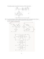
At lagging
power factors,
⎞
V
can
be found from the following relationships:
E
A
⎝
™
⎝
I
A
By the Pythagorean
Theorem,
⎝
jX
I
V
⎞
S
A
I
R
AA
(
)
cos
⎝
2
sin
⎝
2
(
)
cos
⎝
sin
⎝
2
A
E
=
⎞
V
+
R
A
I
A
+
X
S
I
A
+
X
S
I
A
R
A
I
S
V
⎞
=
A
E
2
(
)
⎝
X
S
I
A
cos
R
A
I
S
sin
⎝
2
⎝
R
A
I
A
cos
X
S
I
A
sin
⎝
At unity power
factor,
⎞
V
can be found from the following relationships:
E
A
™
I
A
V
⎞
jX
I
S
A
R
I
AA
By the Pythagorean
Theorem,
(
2
2
=
+
)
2
A
S
E
V
⎞
2
A
X
I
(
)
2
V
⎞
=
A
E
X
S
I
A
At leading
power factors,
⎞
V
can be
found
from the following relationships:
E
A
jX
I
S
A
⎝
I
A
™
⎝
By the Pythagorean
Theorem,
I
R
A
A
⎝
⎞
V
133