Electric Machinery Fundamentals (Solutions Manual) Part 8 pps
Bạn đang xem bản rút gọn của tài liệu. Xem và tải ngay bản đầy đủ của tài liệu tại đây (188.87 KB, 10 trang )
The
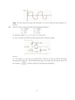
resulting plot is
shown below
260
Synchronous Motor V-Curve
250
240
230
220
210
200
350 400 450 500 550 600 650 700
E (V)
A
6-3.
A 2300-V 1000-hp 0.8-PF leading 60-Hz two-pole
Y-connected
synchronous
motor
has
a
synchronous
reactance of
2.8
&
and an armature resistance of 0.4
&
.
At 60 Hz,
its friction and
windage losses are 24
kW, and
its core losses
are
18 kW.
The field circuit
has
a
dc
voltage
of
200 V,
and the maximum
I
F
is 10
A.
The open-circuit characteristic of this motor is shown in
Figure
P6-1. Answer the following
questions
about the motor, assuming that it is
being supplied by
an infinite bus.
(a)
How much field current would be required to make this machine
operate
at
unity
power
factor
when
supplying full
load?
(b)
What
is the motor’s efficiency at full
load and
unity power factor?
(c)
If
the
field current were increased by 5
percent, what would
the new value
of
the armature current be?
What
would the new power
factor be? How much reactive power is
being consumed
or
supplied
by the
motor?
(d)
What
is
the
maximum
torque
this
machine
is theoretically
capable of supplying at unity power factor?
At 0.8 PF leading?
Note:
An electronic version of this open circuit
characteristic can
be
found
in
fil
p61_occ.dat
,
which
can
be
used
with
MATLAB
programs.
Column
contains
field
current
in
amps, and column 2 contains
open-circuit termina
voltage in
volts.
152
S
OLUTION
(a)
At full
load, the
input power to the motor is
IN
P
=
OUT
P
+
m
P
ech
+
co
P
re
+
CU
P
We can’t know the copper
losses until the armature current
is
known, so
we will find
the
input
power
and
armature current
ignoring that term, and then correct
the
input power after we know
it.
(
)(
)
IN
P
1000 hp
746 W/hp
24 kW
18 kW
78
=
+
8 kW
+
=
Therefore,
the
line and phase
current at unity power
factor
is
P
I
I
=
=
=
788 kW
198
=
A
A L
(
)
3
PF
3
(
)
2300 V
1.0
T
V
The copper
losses
due to a current
of 198 A are
2
(
)
=
=
2
(
)
&
=
CU
3
A
A
P
I
3
19
R
8 A
0.4
47.0 kW
Therefore,
a
better
estimate of the input
power at full load
is
(
)(
)
IN
P
1000 hp
746 W/hp
24 kW
18 kW
47
=
+
kW
83
+
5
kW
+
=
and
a
better
estimate of the line
and phase current
at unity
power factor is
153
P
I
I
=
=
=
835 kW
210
=
A
A L
(
)
3
PF
3
(
)
2300 V
1.0
T
V
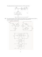
The phasor
diagram of this
motor operating
a
unity power factor
is shown
below:
A
I
V
⎞
A
E
R
I
A
A
jX
I
S
A
The phase voltage of this
motor
is 2300 /
3
= 1328 V.
The required internal generated voltage
is
=
E
V
I
I
A
A
⎞
A S A
R
jX
1328
0
V
(
)
0.4
(
210
0
A
)
(
2.8
)(
210
0
A
)
E
A
=
°
&
°
j
&
°
E
A
1376
25.3
=
V
°
This
internal
generated
voltage corresponds to a terminal voltage of
would require a field current of 4.6 A.
(b)
The motor’s efficiency at full load
and unity
power factor is
⎜
OUT
P
100%
=
⋅
746 k
=
W
100%
⋅
89.3%
=
3
(
)
1376
=
2383 V
. This voltage
IN
P
835 kW
(c)
To
solve this
problem, we will temporarily ignore the effects of the armature
resistance
R
A
.
If
R
A
is
ignored, then
E
A
sin
™
is
directly proportional to
the power supplied by the
motor. Since the power
supplied by the motor does
not
change when
I
F
is changed,
this quantity will
be a constant.
If the field current
is increased by 5%,
then the new field current will
be
4.83
A,
and
the
new
value of
the
open-circuit terminal voltage will be 2450 V. The new value of
Therefore, the new torque
angle
™
will
be
E
A
will be 2450 V
/
3
=
1415 V.
sin
E
1
A
sin
sin
1376 V
™
™
sin
(
)
1 1
=
=
25.
3
24.6
°
=
°
2 1
E
A2
1415 V
Therefore, the new armature
current will
be
⎞
A
V
E
I
1328
0
V
°
141
5
-
25
.3
V
°
214.5
3.5
A
=
=
=
°
A
0.4
2.8
+
+
&
A S
R
jX
j
The
new current is about the same as before, but the phase angle has become positive.
The
new
power
factor is
cos 3.5
°
= 0.998 leading, and the reactive power
supplied by the motor is
3
sin
3
(
2300
V
)(
21
=
=
4.5 A
)
sin
(
3.5
)
52.2 kVAR
°
=
T L
Q
V
I
⎝
(d)
The maximum torque possible
at unity
power factor (ignoring
the
effects
of
3
3
(
1328 V
)
(
1376 V
)
R
A
) is:
⎮
⎞
A
V
E
=
=
ind,max
1 min
2
rad
5193 N
m
=
⊕
⎤
m
S
X
(
)
3600 r/min
(
)
2.8
&
60 s
1 r
154
If we are ignoring the resistance of the motor, then the input power would be 788
kW
(note
that
copper
losses
are ignored!). At a power
factor
of
0.8 leading, the current
flow will be
P
I
I
=
=
=
788 kW
247
=
A
A L
(
)
3
PF
3
(
)
2300 V
0.8
T
V
so
I
A
247
36.8
=
7
A
°
.
The
internal generated
voltage at 0.8 PF leading (ignoring copper losses) is
=
E
V
I
I
A
A
⎞
A S A
R
jX
1328
0
V
(
)
2.8
(
247
36.87
A
)
E
A
=
j
°
&
°
E
A
1829
17.6
=
V
°
Therefore,
the
maximum torque at
a
power factor of 0.8 leading is
3
3
(
1328 V
)
(
1829 V
)
⎮
⎞
A
V E
=
=
ind,max
1 min 2 rad
6093 N
=
m
⊕
⎤
m
S
X
(
)
3600 r/min
(
)
2.8
&
60 s 1 r
6-4.
Plot the V-curves
(
I
A
versus
I
F
)
for the synchronous
motor of
Problem
6-3 at no-load, half-load,
and full-
load
conditions.
(Note
that an
electronic version of the open-circuit
characteristics
in Figure P6-1
is
available at the book’s Web site. It may simplify the
calculations
required by
this
problem.
Also,
you
may
assume that
R
A
is negligible
for
this calculation.)
S
OLUTION
The
input power
at no-load, half-load and full-load
conditions is given below.
Note that we
are
assuming that
R
A
is
negligible in
each case.
IN
P
,nl
24
kW
18 kW
=
+
42 kW
=
(
)(
)
IN
P
,half
500 hp
746 W/hp
24
kW
18 kW
3
=
+
73
kW
+
=
(
)(
)
IN
P
,full
1000 hp
746 W/hp
24 kW
18 kW
78
=
+
8 kW
+
=
If the power factor
is adjusted to
unity,
then armature currents will be
I
P
42 kW
=
=
10.5 A
=
A
,nl
3
PF
3
(
)
2300 V
(
1.0
)
T
V
I
P
373 kW
=
=
93.6 A
=
A,fl
3
PF
3
(
)
2300 V
(
1.0
)
T
V
I
P
788 kW
=
=
198 A
=
A,fl
3
PF
3
(
)
2300 V
(
1.0
)
T
V
The corresponding
internal
generated
voltages at unity power
factor are:
=
E
V
I
A
S
⎞
jX
A
(
)(
)
E
A,nl
1328
0
V
=
j
°
2.8
10.5
&
0
A
°
1328.
=
3
1.27
V
°
(
)(
)
E
,h
A
alf
1328
0
V
=
j
°
1.5
93.6
&
0
A
°
1354
=
11.2
V
°
(
)(
)
E
A,full
1328
0
V
=
j
°
2.8
198
&
0
A
°
1439
=
22.
7
V
°
These
values
of
E
A
and
™
at
unity
power
factor
can
serve
as
reference
points
in
calculating
the
synchronous motor V-curves. The MATLAB program to solve this problem
is shown below:
155
% M-file: prob6_4.m
% M-file
create
a plot of armature current versus
field
%
current
for the synchronous motor of Problem 6-4
at
%
no-load, half-load, and
full-load.
% First,
initialize the field current values (21 values
% in the
range
3.8-5.8 A)
If =
2.5:0.1:8;
% Get
the OCC
load p61_occ.dat;
if_values =
p61_occ(:,1);
vt_values =
p61_occ(:,2);
% Now
initialize all other values
Xs
= 1.5;
% Synchronous
reactance
Vp
= 1328;
% Phase voltage
% The
following
values of Ea and delta are for
unity
% power factor. They
will serve as reference values
% when calculating
the V-curves.
d_nl = -1.27 *
pi/180;
% delta at
no-load
d_half =
-11.2
* pi/180;
% delta at
half-load
d_full =
-22.7
* pi/180;
% delta
at
full-load
Ea_nl
= 1328.3;
% Ea at no-load
Ea_half = 1354;
% Ea at half-load
Ea_full = 1439;
% Ea at full-load
%%%%%%%%%%%%%%%%%%%%%%%%%%%%%%%%%%%%%%%%%%%%%%%%%%%%%%
% Calculate
the actual Ea corresponding
to each level
% of field current
%%%%%%%%%%%%%%%%%%%%%%%%%%%%%%%%%%%%%%%%%%%%%%%%%%%%%%
Ea =
interp1(if_values,vt_values,If) /
sqrt(3);
%%%%%%%%%%%%%%%%%%%%%%%%%%%%%%%%%%%%%%%%%%%%%%%%%%%%%%
% Calculate
the armature
currents
associated with
% each value of Ea
for the no-load case.
%%%%%%%%%%%%%%%%%%%%%%%%%%%%%%%%%%%%%%%%%%%%%%%%%%%%%%
%
First, calculate delta.
delta
= asin (
Ea_nl ./ Ea .* sin(d_nl)
);
% Calculate
the phasor Ea
Ea2
= Ea .* (cos(delta)
+
j .* sin(delta));
% Now
calculate Ia
Ia_nl
= ( Vp - Ea2
) / (j *
Xs);
%%%%%%%%%%%%%%%%%%%%%%%%%%%%%%%%%%%%%%%%%%%%%%%%%%%%%%
% Calculate
the armature
currents
associated with
% each value of Ea
for the half-load
case.
%%%%%%%%%%%%%%%%%%%%%%%%%%%%%%%%%%%%%%%%%%%%%%%%%%%%%%
%
First, calculate delta.
delta
= asin (
Ea_half ./ Ea .* sin(d_half)
);
% Calculate
the phasor Ea
Ea2
= Ea .* (cos(delta)
+
j .* sin(delta));
156
% Now
calculate Ia
Ia_half = (
Vp - Ea2 ) /
(j
* Xs);
%%%%%%%%%%%%%%%%%%%%%%%%%%%%%%%%%%%%%%%%%%%%%%%%%%%%%%
%
Calculate the armature currents associated
with
% each value of Ea
for the full-load
case.
%%%%%%%%%%%%%%%%%%%%%%%%%%%%%%%%%%%%%%%%%%%%%%%%%%%%%%
%
First, calculate delta.
delta
= asin (
Ea_full ./ Ea .* sin(d_full)
);
% Calculate
the phasor Ea
Ea2
= Ea .* (cos(delta)
+
j .* sin(delta));
% Now
calculate Ia
Ia_full = (
Vp - Ea2 ) /
(j
* Xs);
%%%%%%%%%%%%%%%%%%%%%%%%%%%%%%%%%%%%%%%%%%%%%%%%%%%%%%
% Plot the v-curves
%%%%%%%%%%%%%%%%%%%%%%%%%%%%%%%%%%%%%%%%%%%%%%%%%%%%%%
plot(If,abs(Ia_nl),'k-','Linewidth',2.0);
hold on;
plot(If,abs(Ia_half),'b ','Linewidth',2.0);
plot(If,abs(Ia_full),'r:','Linewidth',2.0);
xlabel('\bfField Current
(A)');
ylabel('\bfArmature Current
(A)');
title
('\bfSynchronous Motor V-Curve');
grid on;
The resulting
plot
is
shown
below. The flattening
visible to the right of the V-curves is due to magnetic
saturation in the machine.
6-5.
If a 60-Hz synchronous motor
is to be
operated at
50 Hz, will its synchronous reactance be the
same as at
60
Hz, or will
it change?
(Hint:
Think about the derivation
of
X
S
.)
157
S
OLUTION
The
synchronous
reactance
represents the effects of the armature reaction
voltage
E
stat
and
the
armature self-inductance. The
armature reaction voltage is caused by
the armature
magnetic field
B
S
, and
the
amount of voltage is directly proportional to the speed with which the magnetic field sweeps
over
the
stator surface.
The
higher the frequency, the faster
B
S
sweeps over the stator, and
the
higher the armature
reaction voltage
E
stat
is. Therefore, the armature reaction
voltage
is
directly
proportional
to
frequency.
Similarly, the reactance of the armature self-inductance is directly
proportional
to
frequency,
so
the
total
synchronous reactance
X
S
is
directly
proportional
to
frequency.
If the frequency is
changed from 60 Hz
to
50
Hz, the synchronous
reactance
will be
decreased
by a factor
of 5/6.
6-6.
A 480-V
100-kW 0.85-PF leading 50-Hz six-pole Y-connected synchronous motor has a
synchronous
reactance of 1.5
&
and
a
negligible armature
resistance.
The
rotational losses are also to be ignored. This
motor
is
to
be
operated
over a continuous
range of speeds from 300 to
1000 r/min, where the speed changes
are
to
be
accomplished by
controlling the system frequency
with a solid-state
drive.
(a)
Over what range
must
the
input frequency be
varied to provide
this speed control range?
(b)
How large is
E
A
at the motor’s rated conditions?
(c)
What
is the maximum
power the motor can
produce at
the
rated conditions?
(d)
What
is the largest
E
A
could
be at
300 r/min?
(e)
Assuming
that the applied voltage
V
⎞
is derated by the same amount as
E
A
, what is the maximum
power the motor could supply at 300
r/min?
(f)
How does the power capability of a synchronous
motor
relate to its speed?
S
OLUTION
(a)
A
speed of 300 r/min
corresponds to a frequency
of
(
300 r/min
)
(
)
6
e
f
m
n
P
=
=
120
120
15 Hz
=
A speed of 1000 r/min
corresponds
to a frequency
of
(
)
1000 r/min
e
f
m
n
P
=
=
120
120
(
)
6
50 Hz
=
The frequency must be controlled
in the range 15
to 50 Hz.
(b)
The
armature
current at rated conditions is
P
I
I
=
=
=
100 kW
141.
=
A L
(
)
3
PF
3
(
)
480 V
0.85
T
V
5 A
so
I
A
141.5
31.8
=
A
°
. This machine is
Y-connected, so the phase voltage is
V
⎞
= 480 /
3
= 277 V.
The internal generated
voltage is
=
E
V
I
I
A
A
⎞
A S A
R
jX
277
0
V
(
)
1.5
(
141.5
31.8
A
)
E
A
=
°
j
&
°
E
A
429
24
=
.9
V
°
So
E
A
= 429 V at rated conditions.
(c)
The maximum power that
the
motor
can produce
at rated
speed with the value of
E
A
from part
(b)
is
158