Design and Optimization of Thermal Systems Episode 1 Part 4 pps
Bạn đang xem bản rút gọn của tài liệu. Xem và tải ngay bản đầy đủ của tài liệu tại đây (407.65 KB, 25 trang )
47
2
Basic Considerations
in Design
The important terms that arise in the design and optimization of thermal systems
have been dened and discussed in the preceding chapter. We are concerned with
thermal systems that are governed by considerations of uid ow, thermodynam-
ics, and heat and mass transfer. The interaction between the various components
and subsystems that constitute a given system is an important element in the
design because the emphasis is on the overall system. Additional considerations,
that may not have a thermal or even a technical basis, also have to be included in
most cases for a realistic and successful design. Though selection of components
or devices may be employed as part of system design, the focus is on design and
not on selection. Similarly, analysis is used only as a means for obtaining the
inputs needed for design and for evaluating different designs, not for providing
detailed information and understanding of thermal processes and systems. The
synthesis of information from a variety of sources plays an important part in the
development of an acceptable design. With this background and understanding,
we can now proceed to the basic considerations that arise in the design process.
2.1 FORMULATION OF THE DESIGN PROBLEM
A very important aspect in design, as in other engineering activities, is the formu-
lation of the problem. We must determine what is required of the system, what is
given or xed, and what may be varied to obtain a satisfactory design. The nal
design obtained must meet all the requirements, while satisfying any constraints
or limitations due to safety, environmental, economic, material, and other consid-
erations. The design process depends on the problem statement, as does the evalu-
ation of the design. In addition, the formulation of the problem allows us to focus
our attention on the quantities and parameters that may be varied in the system.
This gives the scope of the design problem, ranging from relatively simple cases
where only a few quantities can be varied to more complicated cases where most
of the parameters are variable.
2.1.1 REQUIREMENTS AND SPECIFICATIONS
Certainly the most important consideration in any design is the desired function
or task to be performed by the system. This may be given in terms of require-
ments to be met by the system. A successful, feasible, or acceptable design must
satisfy these. The requirements form the basis for the design and for the evalu-
ation of different designs. Therefore, it is necessary to express the requirements
48 Design and Optimization of Thermal Systems
quantitatively and to determine the permitted variation, or tolerance level. Sup-
pose a water ow system is needed to obtain a specied volume ow rate R
o
.
Since there may be variations in the operating conditions that may result in
changes in the ow rate R, it is essential to determine the possible increase or
decrease in the ow rate that can be tolerated. Then the system is designed to
deliver the desired ow rate R
o
with a possible maximum variation of o ΔR. This
may be expressed quantitatively as
R
o
ΔR a R a R
o
ΔR (2.1)
If a water cooler is being designed, the ow rate R
o
and the desired temperature
T
o
at the outow become the requirements. The former is expressed as given in
Equation (2.1) and the latter as
T
o
ΔT a T a T
o
ΔT (2.2)
where o ΔT is the acceptable variation in the outow temperature.
In the design of thermal systems, common requirements concern tempera-
ture distributions and variations with time, heat transfer rates, temperature lev-
els, and ow rates. Total pressure rise, time needed for a given process, total
energy transfer, power delivered, rotational speed generated, etc., may also be
the desired outputs from a thermal system, depending on the particular applica-
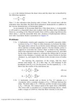
tion under consideration. Consider the thermal annealing process for materials
such as steel and aluminum. The material is heated to a given elevated tempera-
ture, known as the annealing temperature; held at this temperature level for
a specied time, as obtained from metallurgical considerations of the chosen
material; and then cooled very gradually, as shown in Figure 2.1. By heating
Time
Envelope of acceptable
temperature variation
Desired temperature
variation
CoolingSoakingHeating
Annealing temperature
Temperature
FIGURE 2.1 Required temperature variation, with an envelope of acceptable variation,
for the thermal process of annealing of a given material.
Basic Considerations in Design 49
the material beyond a particular temperature T
o
, known as its recrystallization
temperature, and maintaining it at this temperature, the internal stresses are
relieved and the microstructures become relatively free to align themselves. A
slow cooling allows the removal of residual and thermal stresses and renement
of the structure to restore the ductility of the material. The desired tempera-
ture cycle, including the maximum allowable temperature at which the process
becomes unsatisfactory and the acceptable variation in the cycle, are shown in
the gure. The duration T
soaking
, over which the temperature is held constant,
within the two limits shown, is known as the soaking time and is also deter-
mined by metallurgical considerations of the material. These requirements may,
thus, be written quantitatively as
T
reqd
q T
o
, T
soaking
qT
o
,
t
t
a
T
B
T
cooling
(2.3)
where T
o
, T
o
, and B are specied constants, obtained from the basic charac-
teristics of the given material. The acceptable variations in these constants,
often given as percentages of the desired values, may also be included in these
equations. Then, a thermal system is to be designed so that the given mate-
rial or body is subjected to the required temperature cycle, with the allowable
tolerance.
Similarly, the requirements for other thermal systems outlined in Chapter 1
may be considered. For instance, the mass ow rate, as well as the tempera-
ture and pressure at the inlet to the die in the plastic extrusion process, shown
in Figure 1.10(b), are the requirements for a screw extruder. The rate of heat
removal and the lowest temperature that can be obtained in the freezer could
be taken as the requirements for a refrigeration system. The maximum power
delivered and speed attained could be the requirements for a transportation sys-
tem. The energy removal rate and the maximum allowable temperature of the
electronic devices may be the requirements for a cooling system for electronic
equipment.
It is critical to determine the main requirements of the system and to focus
our efforts on satisfying these. Since it is often difcult to meet all the desired
features of the system, requirements that are not particularly important for the
chosen application may have to be ignored. It is best to rst satisfy the most essen-
tial requirements and then attempt to satisfy other less important ones by varying
the design within the specied constraints and limitations. For instance, after a
refrigeration system has been designed to provide the specied temperature and
heat removal rate, effort may be exerted to nd a substitute for the refrigerants
R-11 and R-12, both of which are chlorouorocarbons, or CFCs; to replace the
compressor with one that is more efcient; to vary the dimensions of the freezer;
or to improve the temperature control arrangement. Thus, it is important to rec-
ognize the main requirements of the system and to design the system to achieve
these, rather than consider every desired feature of the system.
50 Design and Optimization of Thermal Systems
Specifications
The system designed on the basis of the given requirements can be described
in terms of its main characteristics. These form the product design specica-
tions, which list the requirements met by the system and the outputs from the
design process that characterize the system. The nal specications of the system
may include the performance characteristics; expected life of the system; recom-
mended maintenance, weight, size, safety features; and environmental require-
ments. For instance, the specications of a heat exchanger could be the overall
heat transfer rate for given uids and its dimensions. For a water chilling system,
these could be the lowest attainable temperature and the corresponding ow rate
and power consumption. The specications of the system are, thus, the means of
communication between the consumer and the designer/manufacturer.
2.1.2 GIVEN QUANTITIES
The next step in the formulation of the design problem is the determination of
the quantities that are given and are, thus, xed. These items cannot be changed
and, as such, are not varied in the design process. Materials, dimensions, geom-
etry, and the basic concept or method, particularly the type of energy source,
are some of the features commonly given in the design of a thermal system.
Thus, some of the materials and dimensions may be given, while others are
to be determined as part of designing the system. For a particular system, if
most of the parameters are xed, the design problem becomes relatively simple
because only a small number of variables are to be determined. If the basic
concept is not xed, different concepts may be considered, resulting in consid-
erable exibility in the design.
Let us consider the injection molding process for plastics, as shown schemati-
cally for two different machines in Figure 2.2. It is similar to the metal casting
process described earlier and is thus a system dominated by heat transfer and
uid ow considerations (Tadmor and Gogos, 1979). It is an extensively used
manufacturing process for a variety of parts ranging from plastic cups and toys
to bathtubs, car bumpers, and molded parts made of composite materials. As
shown here, the polymer is melted and injected into a mold cavity by applying
force on the melt by means of a plunger or a rotating screw. As the polymer starts
to solidify, additional amounts of melt may be injected to ll the gaps left due
to shrinkage during solidication. The mold is held together by a clamping unit,
which opens and closes the mold and also ejects the nal solidied product.
For system design, the mold and the injected material may be kept xed, while
the melting and injection processes are varied. Similarly, the mold, as well as the
material, may be varied while keeping the rest xed. The system is a complicated
one, but it can be considerably simplied by keeping several components and fea-
tures xed while a few components, such as the injection mechanism, are varied
during design. In addition, the basic concept may be kept unchanged, using, for
instance, either of the two schemes shown in the gure. Other approaches to melt
Basic Considerations in Design 51
and inject the mold, as well as to clamp and open the mold, are also possible. All
these considerations substantially inuence the design process.
Similarly, in the design of an electronic system, consisting of electronic com-
ponents located on circuit boards, the electronic component size, the geometry
and dimensions of the board, the number of electronic components on each board,
and the distance between two boards may be given. The design then focuses on
the cooling system, such as a fan and duct arrangement. A two-stroke engine may
be chosen for the design of a transportation system, thus xing the basic concept.
In a solar energy system, sensible heat storage in water may be chosen as the
concept, with the dimensions, geometry, and material of the tank being varied
for the design. In the design of a cooling pond for a power plant, the location of
the pond, which determines the local ambient conditions, is xed. In all of these
cases, some of which are considered in later chapters, the given quantities are kept
unchanged during the design process.
2.1.3 DESIGN VARIABLES
The design variables are the quantities that may be varied in the system in order
to satisfy the given requirements. Therefore, during the design process, atten-
tion is focused on these parameters, which are varied to determine the behavior
Reciprocating
screw
(a)
(b)
Barrel
Hopper
Ram
Mold
Torpedo
FIGURE 2.2 (a) Ram-fed injection molding machine; (b) screw-fed injection molding
machine. (Adapted from Tadmor and Gogos, 1979.)
52 Design and Optimization of Thermal Systems
of the thermal system and are then chosen so that the system meets the given
requirements. As mentioned earlier, it is important to focus on the main design
variables in the problem because the complexity of the design procedure is a
strong function of the number of variables.
Let us consider again the plastic injection molding system discussed in the
preceding section and shown in Figure 2.2. If only the cooling of the mold is left
to be designed, while the other components in the system are xed, the problem
is considerably simplied. However, even this is an involved design problem and
has generated much interest and effort over the last two decades. Cooling may be
achieved by the ow of a cooling uid through channels in the mold. Different
types, congurations, and dimensions of cooling channels may be considered,
obtaining the thermal characteristics of the system for each case. The solidi-
cation rate and temperature gradients in the material are usually given as the
requirements that must be satised by using a variety of cooling channels. This
leads to a domain of acceptable designs. An appropriate design may be chosen
based on additional considerations such as cost, power requirements, size, etc.
If the other components of the system, such as geometry and dimensions of the
melting and injection section, are to be varied as well, the design becomes much
more involved and the domain of acceptable designs is much larger.
The design variables are usually taken to represent the hardware of the
system such as the plunger, heating arrangement, mold, clamping unit, cooling
channels, and so on, in the above example. However, the system performance
is also affected by the operating conditions, which can be adjusted over ranges
determined by the hardware. Therefore, the variables in the design problem
may be classied as:
Hardware
This includes the components of the system, dimensions, materials, geometrical
conguration, and other quantities that constitute the hardware of the system.
Varying these parameters generally entails changes in the fabrication and assem-
bly of the system. As such, changes in the hardware are not easy to implement
if existing systems are to be modied for a new design, for a new product, or for
optimization.
Operating Conditions
These refer to quantities that can often be varied relatively easily, over specied
ranges, without changing the hardware of the given system, such as the settings
for temperature, ow rate, pressure, speed, power input, etc. The design process
would generally yield the ranges for such parameters, with optimization indicat-
ing the values at which the performance is optimal.
The design of a thermal system must include both types of variables and the
nal design obtained must indicate the materials, dimensions, and congurations
of the various components, as well as the ranges over which the operating condi-
tions such as pressure, temperature, and ow rate may be varied. These ranges
Basic Considerations in Design 53
are xed by the hardware design; for instance, the temperature range may be
determined by the heaters employed or ow rates by the pumps chosen. However,
because the product obtained is a function of the operating conditions, these are
often given as part of the specications of the system.
Example 2.1
For the plastic screw extrusion system sketched in Figure 1.10(b), give the hardware
variables and the operating conditions in the problem.
Solution
The physical system under consideration consists of the following main parts: bar-
rel, heating/cooling arrangement, screw, die, feed hopper, and the drive mechanism,
which includes the motor, bearings, and gear system. Therefore, the hardware vari-
ables can be listed as
1. Geometry, material, and dimensions of the hopper
2. Geometry, material, and dimensions of the barrel
3. Dimensions, energy requirements, and conguration of heating/cooling
arrangement
4. Diameter and material of the screw
5. Shape, height, thickness, and pitch of screw ights
6. Geometry, material, and dimensions of the die
7. Physical characteristics of the drive, motor, and gear system
Clearly, the above list includes a large number of variables. A design problem in
which all of these can be varied is extremely complicated. Therefore, several of
these are generally kept xed and the ranges over which the others can be varied
are determined from physical constraints, availability of parts, and information
available from similar systems.
The operating conditions refer to the quantities that may be varied without
changing the hardware. These may be listed as
1. Plastic ow rate or throughput
2. Speed (revolutions/minute)
3. Temperature distribution at the barrel
4. Material used
All of these operating conditions can be varied over ranges that are determined
by the hardware design of the system. In addition, in actual practice these may not
be varied completely independent of each other. For instance, the screw geometry
and dimensions, along with the speed, will determine the maximum ow rate in the
extruder. The heating/cooling arrangement determines the range of temperature
variation. The plastic or polymer used may limit the speed or the temperature level,
and so on.
2.1.4 CONSTRAINTS OR LIMITATIONS
The design must also satisfy various constraints or limitations in order to be
acceptable. These constraints generally arise due to material, weight, cost, avail-
ability, and space limitations. The maximum pressure and temperature to which
54 Design and Optimization of Thermal Systems
a given component may be subjected are limited by the properties of its material.
For instance, a plastic or metal component may be damaged if the temperature
exceeds the melting point. The performance of semiconductor devices is very
sensitive to the temperature and, therefore, the temperatures in electronic equip-
ment are constrained to values less than 100nC. The pressure rise in a thermal
system is constrained by the strength of the materials at the operating temperature
levels. Such constraints may be written for temperature T, pressure P, and volume
ow rate R as
T a T
max
, P a P
max
, R a R
max
(2.4)
Generally, the maximum values, indicated here by the subscript max, would be
considerably less than levels at which permanent damage to the component or sys-
tem might occur. Therefore, T
max
may be taken as, say, 50nC lower than the melting
point of the material of which a given component is made, depending on the desired
safety, accuracy of the model on which the design is based, and the material.
The choice of the material itself may be limited by cost, availability, waste
disposal, and environmental impact even if a particular material has the best
characteristics for a given problem. In fact, material selection is a very important
element in design, as discussed later in this chapter. Volume and weight restric-
tions also frequently limit the domain of acceptable design. Again, these may be
given as
W a W
max
, L a L
max
, V a V
max
(2.5)
where W, L, and V are the weight, length, and volume, respectively. Such con-
straints arise from the expected application of the system. For instance, weight
restrictions are very important in the design of portable computers, airplanes,
rocket systems, and automobiles. Similarly, volume constraints are important
in room air conditioners, household refrigerators, and industrial furnaces. All
such constraints and limitations determine the range of the design variables and,
thus, indicate the boundaries of the domain over which an acceptable design is
sought.
Constraints also arise due to conservation principles. For instance, mass
conservation dictates the speed of withdrawal in a hot rolling process. For a
two-dimensional at plate being reduced in thickness from D
1
to D
2
across a set
of rollers, as shown in Figure1.10(d), mass conservation leads to the equation
U
1
D
1
U
2
D
2
, where U
1
is the speed before the rollers and U
2
after, if the density
of the material remains unchanged. Then this equation serves as a constraint on
the speed after the rollers if the remaining quantities are specied.
Similarly, the energy rejected Q
rejected
from a power plant to a cooling pond is
mC
p
ΔT, where
m is the mass ow rate of the cooling water, ΔT is its temperature
rise in going through the condensers, and C
p
is the specic heat. This energy must
be rejected to the environment through heat loss at the water surface and to the
ground. If the latter is negligible, as is often the case, the surface temperature must
Basic Considerations in Design 55
rise in order to lose the energy to the ambient medium. An energy balance equation
may thus be written to determine the average surface temperature rise as
Q
rejected
mC
p
ΔT hA
surface
(T
new
T
old
)(2.6)
where h is the overall heat transfer coefcient, A
surface
is the surface area, and
(T
new
– T
old
) is the rise in the average surface temperature. A limitation of around
5nC on this temperature rise is specied by federal, state, county, or city regula-
tions directed at minimizing the environmental effect. Therefore, the maximum
amount of energy that may be rejected to the pond may be calculated. Similar
considerations could lead to restrictions on temperature rise in the condensers, as
well as on the total ow rate (Moore and Jaluria, 1972).
2.1.5 ADDITIONAL CONSIDERATIONS
Several additional considerations have to be taken into account for obtaining an
acceptable or workable design. These considerations may arise from safety and
environmental concerns, procurement of supplies needed, availability of raw
materials, national interests, import and export concerns, waste disposal problems,
nancial aspects, existing technology, and so on. Many of these aspects affect
the overall engineering enterprise, as discussed earlier in Chapter 1. However,
the design itself may be strongly inuenced by these considerations, particularly
those pertaining to the environmental and safety issues. For instance, even though
nuclear energy is one of the cheapest and cleanest methods of generating electric-
ity, concerns on radioactive releases have strongly curbed the growth of nuclear
power systems. Systems are designed in the steel industry to use the hot combus-
tion products from the blast furnace in order to reduce the discharge of pollutants
and thermal energy into the environment, while also decreasing the overall energy
input. Thermal pollution concerns could make it undesirable to depend only on a
lake or river for discharge of thermal energy from a power plant, making it neces-
sary to design additional systems such as cooling towers for heat disposal.
Disposal of solid waste, particularly hazardous waste from chemical plants and
radioactive waste from nuclear facilities, is another very important consideration that
could substantially affect the design of the system. The energy source is chosen in
order to meet the federal or state guidelines for solid waste disposal. Adequate arrange-
ments have to be included in the design to satisfy waste disposal requirements.
Safety concerns, particularly with nuclear facilities, demand that adequate
safety features be built into the system. For instance, if the temperature or heat
ux levels exceed safe values, the system must shut down. If the uid level were
too low in a boiler, a safety feature would not allow it to be turned on, thus
avoiding damage to the heaters and keeping the operation safe. Similarly, the
energy source may be changed from gas to electricity because of safety concerns
in an industrial system. An oil furnace may be developed instead of a gas furnace
for the same reason.
56 Design and Optimization of Thermal Systems
The formulation of the design problem is based on all of the above aspects.
Therefore, before proceeding to the design of the thermal system, the problem
statement is given in terms of the following:
1. Requirements
2. Given quantities
3. Design variables
4. Limitations or constraints
5. Safety, environmental, and other considerations
Since the design strategy, evaluation of the designs developed, and nal design
are all dependent on the problem statement, it is important to ensure that all of
these aspects are considered in adequate detail and quantitative expressions are
obtained to characterize these. It is worthwhile to investigate all important con-
siderations that may affect the design and to formulate the design problem in
exact terms, as far as possible, along with allowable variations or trade-offs in
the various quantities and parameters of interest. Once the design problem is
formulated, we can proceed to the development of the design, starting with the
basic concept.
Example 2.2
An air-conditioning system is to be designed for a residential building. The inte-
rior of the building is to be maintained at a temperature of 22 o 5nC. The ambient
temperature can go as high as 38nC and the rate of heat dissipated in the house is
given as 2.0 kW. The location, geometry, and dimensions of the building are given.
Formulate the design problem and give the problem statement.
Solution
The given quantities are the maximum ambient temperature, which is 38nC, and the
rate of energy input due to activities in the house, specied as 2.0 kW. The location,
geometry, and dimensions of the house are all xed quantities. The requirements
for the system to be designed are given in terms of the temperature range, 17–27nC
(22 – 5nC to 22 5nC), which is to be maintained in the house. No constraints are
given in the problem. However, typical constraints will involve limitations on the
size and volume of the system, on the ow rate of air circulating in the building,
and on the total cost. Use of chlorouorocarbons (CFCs) as refrigerants may be
unacceptable due to environmental considerations.
The thermal load due to heat transfer to the house from the ambient must be
determined. This load will involve absorbed solar ux, back radiation to the envi-
ronment, convective transport from ambient air, evaporation or condensation of
moisture, and conductive energy loss to the ground. The ambient thermal load is
a function of ambient conditions, geometry of the building, its geographical loca-
tion, and dimensions. It can often be modeled as hAΔT, where h is the overall heat
transfer coefcient, A is the total surface area, and ΔT is the temperature difference
between the ambient and the house. The total thermal load Q is then the ambient
load plus the rate of energy dissipated in the building. The rate of heat removal Q
r
by the thermal system shown in Figure 2.3 must be greater than this total load.
Basic Considerations in Design 57
The transient cooling of the building is also an important consideration. If the
total thermal capacity of the building (mass X specic heat) is estimated as S, then
its average temperature T is governed by the energy balance equation
S
dT
dT
Q – Q
r
From this equation, the time T
r
needed to cool the building to 1/e of its initial tem-
perature difference from the ambient, i.e., the characteristic response time, may be
calculated, as discussed in Chapter 3. If this time is posed as a requirement, the heat
removal rate Q
r
or the capacity of the system may be appropriately determined; other-
wise Q
r
must simply be greater than Q.
The system is designed for the highest load, which arises at an ambient tempera-
ture of 38nC and inside temperature of 17nC. Simulation is used to determine the
effect of ambient conditions as well as the transient response of the building. From
these considerations, an acceptable design is obtained for the given design problem.
The problem statement for the given system design may, thus, be summarized as
Given: Building geometry, location, and dimensions. Maximum ambient tem-
perature as 38nC. Rate of heat dissipated inside the house as 2.0 kW.
Requirements: Temperature inside the building must be maintained within 17 and 27nC.
In typical cases, the rate of cooling or response time T
r
is also a requirement.
Constraints: Limitations on size, volume, weight, and cost of air conditioner.
Also on maximum air ow rate circulating in the house.
Design variables: Systems parts, such as condenser, evaporator, compressor, and
throttling valve. Also, the refrigerant may be taken as a design variable.
Because of these requirements and constraints, the evaporator must operate at
temperatures lower than 17nC to extract heat at the lowest temperature in the build-
ing. The condenser must operate at temperatures higher than 38nC in order to reject
heat at the highest ambient temperature. Similarly, the total load will determine the
capacity of the system. This specication is usually given in tons, where 1 ton is
3.52 kW and refers to the energy removal rate required to convert one ton (2000 lb)
of water to ice in one day. A thermostat control with an on/off mechanism is often
used with the designed thermal system to maintain the desired temperature levels.
FIGURE 2.3 A thermal system for air conditioning a house.
58 Design and Optimization of Thermal Systems
2.2 CONCEPTUAL DESIGN
At the very core of any design activity lies the basic concept for the process or the
system. The design effort starts with the selection of a conceptual design, which is
initially expressed in vague terms as a method that might satisfy the given require-
ments and constraints. As the design proceeds, the concept becomes better dened.
Conceptual design is a creative process, though it may range from something inno-
vative, representing an invention or a new approach not employed before, to modi-
cations in existing systems. Inventions may lead to patents, as discussed later.
Creativity, originality, experience, knowledge of existing systems, and information
on current technology play a large part in coming up with the conceptual design.
For instance, microprocessors, laser-Doppler velocimeters, ultrasonic probes,
composite materials, iPod, digital cameras, and liquid crystals represent some of
the innovative ideas introduced in recent years. Solutions based on existing and
developing technology can also lead to valuable conceptual designs such as those
of interest in computer workstations, automobile fuel injection systems, hybrid
cars, and solar power stations. Changes can be made in existing systems to meet
the given need or opportunity. In fact, much of the present design and development
effort is based on improvements in current processes and systems.
For a given problem statement, several concepts or ideas may be considered
and evaluated to estimate the chances of success. The ideas at this stage are nec-
essarily fuzzy and rough estimates are carried out to determine if the concepts
are feasible or if there are problems that may be difcult to overcome. Sometimes,
these are simply back-of-the-envelope calculations that yield the overall inputs,
outputs, expected ranges, etc. Such estimates allow the design group to narrow
down the selection of the conceptual design to a few possible approaches. The
selected conceptual designs are then subjected to the detailed design process,
which would yield an acceptable design, if possible.
In order to illustrate the availability of different concepts and the choice of the
most suitable one, let us consider the task of transporting coal from the loading
dock to the blast furnace in a steel plant. Obviously, this can be achieved in many
ways. Trucks, trains, conveyor belts, pipes, and carts are some of the methods that
may be used. Each of these represents a different concept for the transportation
system. The nal choice is guided by the distance over which the material is to be
transported, size and form in which coal is available, and rate at which the mate-
rial is to be fed. For small plants, individual carts and trucks driven by workers
may be adequate, whereas trains may be the most appropriate method for large
distances and large plants. Clearly, there is no unique answer. In addition, within
each concept, different techniques may be used to achieve the desired goals.
2.2.1 INNOVATIVE CONCEPTUAL DESIGN
Innovative and original ideas can lead to major advancements in technology and
must, therefore, be encouraged. Not all original concepts are earth shaking and not
all of these are practical. However, an environment conducive to the generation of
Basic Considerations in Design 59
original and innovative solutions to the given problem must be maintained and
various ideas brought forth must be examined before they are discarded. Such
ideas may originate in different divisions within a company, such as manufactur-
ing, research and development, and marketing. In many cases, the concept may
be infeasible because of cost, technical limitations, availability of materials, and
so on. But the concepts that appear to have promise must be considered further to
determine if it is possible to develop a successful design based on them.
It is not easy to teach someone how to be creative and innovative. In most
cases, creativity is a natural talent and some people tend to be more original than
others. There are no set rules that one might follow to become creative. However,
experience with current technology and knowledge of systems being used for
applications similar to the one under consideration are a big help in the search for
a suitable conceptual design. In addition, it is necessary to provide an environ-
ment that is open to new ideas. Creative problem solving requires imaginative
thinking, persistence, acceptance of all ideas from different sources, and con-
structive criticism. Several such methods that may help to develop creative think-
ing are discussed by Alger and Hays (1964) and by Lumsdaine and Lumsdaine
(1995). Techniques such as brainstorming, where a group of people collectively
try to generate a variety of ideas to solve a given problem, design contests, and
awards to employees with the best ideas also promote the generation of innovative
solutions. Many impressive designs, such as the Vietnam Veterans Memorial in
Washington, D.C., have arisen from design competitions.
An Example
In the manufacture of electronic systems, a classical process that is frequently
used is that of soldering a pin to a board. Solid solder is placed around the pin in
the form of a doughnut, as shown in Figure 2.4, and heated to beyond its melt-
ing point. The molten solder is driven by surface tension forces to form a joint,
which solidies on cooling to give the desired connection between the pin and
the copper plated through hole in the board. The heating had traditionally been
done by radiation or by convection, using air or a liquid for immersion. Excessive
and nonuniform heating of the boards was a common problem with radiation.
Cleaning of the uid and low heat transfer rates were the concerns with convec-
tion. In response to the need for an improved technique for this problem, a new
and innovative method based on condensation of a vapor was proposed to yield a
rapid heat transfer rate, while ensuring a clean environment with no overheating
of the board. This resulted in the design of a thermal system to generate the vapor
of a uid with the appropriate boiling point. This vapor would then condense on
a circuit board entering the condensation region, thus heating the material and
forming the desired solder joint. Higher and more uniform heat transfer rates
could be achieved by this method. The quality of the joint and the production
rate were improved. Figure 2.4 gives the basic features of the process and of a
simple condensation soldering system that can be used for such applications.
Figure 2.5 shows a photograph of a condensation soldering facility, based on this
60 Design and Optimization of Thermal Systems
concept, for large electronic components, indicating the typical scale of such
practical systems. Example 2.3 discusses this process in greater detail. Figure 2.6
shows a different type of facility that uses the same basic concept and is avail-
able commercially. This system is more compact, easier to control, and has less
uid loss than the one shown in Figure 2.4(b). Dally (1990) may be consulted for
further details on this and other soldering processes used in the manufacture of
electronic circuitry.
Many such innovative ideas have been introduced in recent years, particu-
larly in the area of materials processing. Consequently, new materials, with a
wide range of desired characteristics, and new processing techniques have been
developed. Graphite tennis rackets, Teon-coated cookware, lightweight camping
equipment, lightweight laptop computers, and many such items in daily use are
examples of these materials. Similarly, concerns with our environment and energy
supply have resulted in many innovative systems for waste disposal, particularly
for solid waste using methods such as incineration, and for unconventional energy
sources such as solar, wind, and geothermal energy. Aerospace engineering is
Terminal
Solder preform
Board
Plated through
hole
Condensing coils
Condensation
interface
Trough
Valve
Condensate
(b)(a)
Vapor
Boiling sump
Heater
Condensed
fluorocarbon
FIGURE 2.4 (a) Solder ow for forming a bond between a pin, or terminal, and a plated
through hole. (b) Schematic of a condensation soldering facility for electronic circuitry
manufacture.
Basic Considerations in Design 61
another area that has beneted from many new and original ideas that arose in
the last three decades in response to the many challenging problems encoun-
tered due to, for example, high temperature, pressure, and velocity during rocket
launching and re-entry. The space program has led to many signicant advances
Surge tank
Moisture condensing
coils
Secondary condensing
coils
Secondary vapor
zone
Primary vapor zone
Boiling fluid
Filtration system
Heaters
Workpiece
carriage
Control panel
Secondary fluid
storage
Secondary fluid
injection
Conveyor drive
CONDENSATION SOLDERING MACHINE
Primary fluid
storage
Primary condensing
coils
FIGURE 2.5 A practical condensation soldering facility. (From Lucent Technologies.
With permission.)
62 Design and Optimization of Thermal Systems
like new alloys and composites, cellular phones, and wireless accessories. Even
in traditional elds, such as automobiles, many new concepts, such as micropro-
cessor control, robotics, GPS navigation systems, and monitoring of the different
subsystems, have been introduced in recent years. Therefore, original and innova-
tive concepts are crucial to the advancement of technology, with some of these
resulting in major changes in current practice while others cause only marginal
improvements. Patents, copyrights, trademarks, and so on, are needed to protect
intellectual property, as discussed later.
2.2.2 SELECTION FROM AVAILABLE CONCEPTS
In an attempt to meet the given design requirements, concepts that have proved
to be successful in the past for similar problems frequently provide a valuable
source of information. With the technological advancements of recent years, a
large variety of problems have been considered and many different solutions have
been tried. In a given industry, the ideas that have been tried in the past to solve
problems similar to the one under consideration are well known. Existing litera-
ture can also be used to generate additional information on various concepts and
solutions that have been previously employed. The conceptual design for a given
problem may then be selected from the list of earlier concepts or developed on
the basis of this information. In this case, only the basic concept is similar to the
earlier concepts; the system design may be quite different.
Let us consider the problem of cooling of electronic equipment. If forced convec-
tive cooling is to be employed for a given electronic circuitry, the extensive information
available in the literature on these cooling systems may be used to select or develop
the conceptual design. Figure 2.7 shows the schematics of some of the arrangements
Ventilation
port
Soldered
PCB
Product
output and
cooling
Condensing
coil
Condensing
surfaces
Heating
elements
Stainless
steel tank
Boiling liquid
fluorocarbon
Ventilation
port
Assembled
printed circuit
board (PCB)
Fluorocarbon vapor
Product
input and
preheat
Reflow soldering
FIGURE 2.6 Condensation soldering machine for surface mounted components. (Adapted
from Dally, 1990.)
Basic Considerations in Design 63
and processes used in practice. Additional information on the characteristics of each
system, for example, on the heat removal rate, pressure needed, dimensions, and cost,
is available in the literature. Based on this information, a particular conceptual design
may be selected from the available techniques for cooling. If none of the approaches
is satisfactory for the given problem, variations of these strategies and concepts may
be used as the conceptual design for the given problem.
The choice of the basic concept from available techniques and methods is
an important approach to conceptual design. It is based on both experience and
information regarding different ideas that have been tried successfully or unsuc-
cessfully in the past. Although the successful concepts are of particular inter-
est, even those ideas that did not yield satisfactory designs must be considered
because of changes in the problem statement and in technology. In some cases,
different concepts may be combined to yield the conceptual design for the given
Two-working-fluid
heat exchanger
IndirectDirect
Liquid
Cold plate
heat exchanger
Tu be a x ia l
Vane axial
Centrifugal
(squirrel
cage)
Centraxial
Blower
Air
Forced convection
cooling
Positive
displacement
Propeller
Radial wheel
Fan
Centrifugal
Backward-
curved
blades
Forward-
curved
blades
Radial
blades
Backward-
curved
blades
Forward-
curved
blades
Radial
blades
FIGURE 2.7 Various arrangements and processes for the forced convective cooling of
electronic systems.
64 Design and Optimization of Thermal Systems
problem. For instance, both forced air cooling with a fan and liquid immersion
cooling may be employed for different parts of an electronic system because of
different heat input levels.
2.2.3 MODIFICATIONS IN THE DESIGN OF EXISTING SYSTEMS
In many cases, existing or available systems may form the basis for design of a
new system to meet the given requirements and constraints of a new application.
This is clearly the simplest approach for obtaining a conceptual design for the
given problem. However, it would work only if relatively small changes in the
requirements are of interest. Improvements in the performance and character-
istics of the system and in the quality of the product can also often be obtained
simply by modifying the design of existing systems. Frequently, optimization
of the system or of the process is achieved by such changes in the design. The
conceptual design is then simply the design of the existing system, along with
the possible modications needed to meet the requirements of the new problem.
The overall conguration of the system is kept largely unchanged and only a
few relevant components or subsystems are varied. Therefore, the design process
becomes relatively simple because many parameters and quantities in the system
are given, reducing the number of design variables.
Making modications in existing systems refers to the use of the information
available on the design of these systems for developing a conceptual design and
not necessarily to physical alterations in actual existing systems, although this
may also be possible in a few cases. The main idea here is to employ existing
systems as the basic framework for design and to consider variations in different
components or parts of the system to satisfy the given problem statement. This is
a very common approach in conceptual design, particularly for complex systems,
because the effort involved is relatively small and because changes in the design
of current systems can often lead to the desired result. Many thermal systems in
use today have evolved through such modications through the years.
Let us consider a few examples where modications in the design of exist-
ing systems may lead to viable conceptual designs. The Rankine cycle is the
basic thermodynamic cycle used for steam power plants. However, the desire to
improve the overall thermal efciency of the system has led to many modica-
tions. Some of the variations in the conceptual design that may be mentioned are
those related to superheating of the vapor leaving the boiler, reheating the steam
passing through the boiler, and regenerative heating of the working uid using
stored energy from an earlier process in the system (Cengel and Boles, 2002). All
of these are different conceptual designs based on an existing system design.
Another example is provided by the plastic screw extrusion process, shown
schematically earlier in Figure 1.10(b). Though electric heaters are generally used,
water or steam circulating in jackets, as shown in Figure 2.8, may also be used to
avoid possible overheating and for better temperature control and higher thermal
efciency. Different jackets may be used to impose a temperature variation along
the axis of the extruder. In a screw extruder, considerable variation in the product
Basic Considerations in Design 65
FIGURE 2.8
Schematic of a single screw extruder heated or cooled by the ow of steam or water in jackets
at the extruder barrel.
66 Design and Optimization of Thermal Systems
is obtained by varying the conguration of the screw. Different types of elements,
such as reverse elements, kneading blocks, and spacer elements, and screws of
different proles and pitch may be used to alter the design of the system. The
die at the end of the extruder may also be varied. Thus, the overall structure and
conguration of the system is unchanged and individual components are varied to
achieve different characteristics and performance. Figure 2.9 shows a photograph
of a practical plastics/food extruder, which is seen to be much more complicated
than the simple sketch given earlier due to the drive and control mechanisms,
feeding system, and other additional features.
For a given application, the preceding three strategies may be employed, as
needed, to obtain the conceptual design. Generally, the effort would rst consider
the possibility of modifying the design of existing systems. If this does not yield a
satisfactory solution, different available concepts would be considered to develop a
FIGURE 2.9 A practical plastics/food extrusion system. (From Center of Advanced Food
Technology, Rutgers University, New Jersey. With permission.)
Basic Considerations in Design 67
conceptual design for the given problem. If even this does not work, new approaches
and techniques will have to be considered. This may lead to new and original con-
ceptual designs. The conceptual design is then subjected to the detailed, quantita-
tive design process, as outlined in the next section, in order to obtain an acceptable
design that satises the given requirements and constraints. Obviously, there are
circumstances where a satisfactory solution to the given problem is not obtained.
Then the problem statement may be examined again or the project terminated.
Example 2.3
For the soldering problem sketched in Figure 2.4, consider different heating strate-
gies to obtain a conceptual design for the condensation process.
Solution
The basic problem under consideration involves heating the solid solder preform so
that it melts and ows under the action of surface tension, gravitational and viscous
forces to yield the solder llet that joins the pin or terminal with the copper-plated
hole and thus with the printed circuit board. The llet solidies on cooling to yield
the desired bond. Figure 2.10 shows the typical variation of the solder temperature
8. Aging
7. Further cooling to room temperature
6. Solidification of solder
5. Initial cooldown
4. Solder flow and approach to equilibrium
3. Further heating and flux action
1. Initial heating
123
Temperature
4 56 7
8
Time
2. Melting of solder
FIGURE 2.10 Typical temperature cycle undergone by a solder joint formed by melting
of a solid perform, followed by solidicaiton.
68 Design and Optimization of Thermal Systems
with time, indicating melting and solidication at constant temperature. In com-
mon electrical circuitry, several such pins occur on each board and we are inter-
ested in a thermal system that achieves:
1. Rapid heating
2. Even heating of board materials
3. No damage to materials by overheating
4. Electrically insulating environment, so that electrical properties are not altered
5. Clean, nontoxic medium
Thermal systems may be designed for different heating mechanisms. Some of
these, along with typical values of the corresponding heat transfer coefcient h for
common geometries and dimensions, are estimated as (Incropera and Dewitt, 2001)
h(W/m
2
·K)
Natural convection in air and gases 5—10
Forced convection in air and gases 50—100
Natural convection in common liquids 350—550
Forced convection in common liquids 500—2,500
Radiative transport 600—10,000
Condensation 600—10,000
Fluidized bed 600—5,000
Convection has the advantage of heating the materials only up to the uid tem-
perature. As such, overheating can be avoided easily by choosing the uid tempera-
ture below the temperature limitation of the materials involved. However, the heat
transfer coefcient for natural convection in air or gases is extremely small. This
is undesirable unless the uid temperature is taken very large to obtain high heat
transfer rates. If this is done, the materials may overheat and be damaged. Forced
convection has higher heat transfer coefcients than natural convection. However,
forced ow is strongly geometry-dependent and can lead to uneven heating due
to separation and wakes, as shown in Figure 2.11(a). In addition, it will affect the
shape of the solder llet by exerting drag on the molten solder.
Natural convection using a liquid is attractive because it has reasonably high heat
transfer coefcients and provides uniform heating. However, immersion in a liquid
has the problem of accumulation of impurities, dust particles, and other undesirable
deposits. Therefore, cleaning is a major concern in this case. Radiation provides a
clean environment, but the heat ux absorbed is a strong function of the geometry and
(b)(a)
Board
Solder
preform
Pin
Flow
ermal
radiation
Mask
Board
Solder preform
Pins
FIGURE 2.11 Heating of the solid solder preform by (a) forced convection and (b) ther-
mal radiation.
Basic Considerations in Design 69
the surface properties of the material. Therefore, overheating is commonly encoun-
tered when radiation is used to heat the preform. Radiation masks, as shown in
Figure 2.11(b), are generally needed to avoid overheating. Different masks are required
for different geometrical congurations, making this a difcult and time-consuming
effort. Fluidized bed heating has the same problems as forced convection.
The previous discussion indicates the kind of thinking that goes into the devel-
opment of a conceptual design. Here, the heat transfer coefcients are obtained
from the literature. Different heating mechanisms are considered and evaluated.
The various strategies for heating, mentioned here, have been employed for differ-
ent applications, despite their shortcomings. Therefore, we come to condensation as
a means to heat the solder preform. This process has a high heat transfer coefcient
and provides uniform heating because an externally induced ow is not involved in
the transport. The environment is clean because vapor obtained by boiling the liq-
uid is used. The impurities, dust particles, and deposits are left behind in the liquid,
which may be cleaned periodically. However, the success of this approach depends
on the availability of a nontoxic vapor at the appropriate temperature. The melting
point is around 182nC for common solders. Therefore, uids with boiling points
higher than this temperature are needed. Several high boiling uorocarbons are
suitable for the purpose because these are nontoxic and relatively inert. However,
these uids are expensive and the system design must consider minimizing uid
losses. Therefore, condensation heating may be chosen for the process.
Even after condensation has been selected as the method for heating and an
appropriate uid has been found, several conceptual designs for the system can be
developed. We need a boiling sump where the liquid is heated to provide the vapor
region where the vapor condenses on the circuitry to heat the preform. The con-
densed vapor must be returned to the sump. One possibility is to have a boiler and
transport the vapor to a condensing chamber where the soldering takes place. The
condensate is then pumped back to the sump. Leakage of the vapor is minimized
by proper design of entry and exit ports for the electronic part. Figure 2.12 shows a
sketch of such an arrangement.
Heat
Pump
Condensed liquid
Condensate
Condensation
region
Electronic
part
Boiler
Vapor
Boiling liquid
Opening
Vapor
FIGURE 2.12 A possible conceptual design for a condensation soldering facility.
70 Design and Optimization of Thermal Systems
The systems shown in Figure 2.4(b) and Figure 2.6 are other conceptual designs.
In these cases, the boiling liquid sump and the condensing vapor region are located
in the same container. Condensing coils, which are cooled by circulating cold water,
condense the vapor and generate a vapor region. If a part is immersed in this region,
the vapor condenses on it and thus heats it at the desirable high heat transfer rates.
Though the vapor region is physically contained in Figure 2.6, it is not contained
in Figure 2.4(a), resulting in greater uid loss in this design. The part to be heated
passes through the top as well. However, the interface generated at the top reduces
the uid loss. Additional mechanisms to minimize uid loss can also be devised
because the uid is generally quite expensive. Again, the conceptual design is not
unique and several other solutions and systems are possible.
2.3 STEPS IN THE DESIGN PROCESS
The conceptual design yields the basic approach and the general features of the sys-
tem. These form the basis of the subsequent quantitative design process. The start-
ing or initial design is then specied in terms of the conguration of the system,
the given quantities from the problem statement, and an appropriate selection of the
design variables. This initial selection of the design variables is based on informa-
tion available from other similar designs, on current engineering practice, and on
experience. Employing approximations and idealizations, a simplied model may
then be developed for this initial design of the system so that its behavior and char-
acteristics may be analyzed. Generally, the system behavior under a variety of con-
ditions is investigated on the computer, by a process known as simulation, because
of the complexity of the governing equations in typical thermal systems. An experi-
mental or physical model may also be employed in some cases. The outputs from
the modeling and simulation effort allow the designer to evaluate the design with
respect to the requirements and constraints given in the problem statement. If an
acceptable design that satises these requirements and constraints is obtained, the
process may be terminated or other designs may be sought with a view to improve
or optimize the system. If an acceptable design is not obtained, the design is varied
and the processes of modeling, simulation, and design evaluation repeated. These
steps are carried out until a satisfactory design is obtained. Different strategies may
be adopted to improve the efciency of this iterative procedure. Figure 2.13 shows a
typical overall design procedure, starting with the conceptual design and indicating
some of the steps mentioned here.
Usually, the engineering design process focuses on the quantitative design
aspects after the problem statement and the conceptual design have been obtained.
Then, the design process starts with the initial design of the physical system and ends
with communication of the design to fabrication and assembly facilities involved in
developing the system. The formulation of the design problem and conceptual design
are precursors to this process and play a major role at various stages. Thus, the main
steps that constitute the design and optimization process may be listed as:
1. Initial physical system
2. Modeling of the system
Basic Considerations in Design 71
3. Simulation of the system
4. Evaluation of different designs
5. Iteration and obtaining an acceptable design
6. Optimization of the system design
7. Automation and control
8. Communicating the nal design
Figure 2.14 shows a schematic of these different steps in the design and opti-
mization of a system. The iterative process to obtain an acceptable design by
varying the design variables is indicated by the feedback loop connecting simu-
lation, design evaluation, and acceptable design. There is a feedback between
simulation and modeling as well in order to improve the model representation of
the physical system based on observed behavior and characteristics of the sys-
tem, as obtained from simulation. Optimization of the system is undertaken after
acceptable designs have been obtained. Automation and control are important
for the satisfactory and safe performance of the given system. The results from
the detailed design and optimization process are nally communicated to groups
involved with the fabrication, sales, and marketing. The basic considerations
Conceptual
design
Initial design
Modeling
and simulation
Evaluation
No
Yes
Acceptable?
Solution
Iterative redesign
FIGURE 2.13 Iterative process to obtain an acceptable design.