Design and Optimization of Thermal Systems Episode 1 Part 6 pdf
Bạn đang xem bản rút gọn của tài liệu. Xem và tải ngay bản đầy đủ của tài liệu tại đây (274.2 KB, 25 trang )
Basic Considerations in Design 97
available in the literature (Incropera and Dewitt, 2001). The use of these correlations
brings in the dependence of the cooling rate on the physical variables in the prob-
lem. The uid is the most important parameter and may be chosen for high thermal
conductivity, which yields a high heat transfer coefcient, low cost, easy availability,
nontoxic behavior, and high boiling point, if boiling is to be avoided in the liquid. If
boiling is allowed, the latent heat of vaporization becomes an important variable to
obtain a high heat transfer coefcient. Oils with high boiling points are generally
used for quenching. The temperature T
a
is another variable that can be effectively
used to control the cooling rate. A combination of a chiller and a hot uid bath may be
used to vary T
a
over a wide range. Clearly, many solutions are possible and a unique
design is not obtained. Different uids that are easily available may be tried rst to
see if the requirement on the cooling rate is satised. If not, a variation in T
a
may be
considered. Optimization of the system may then be based on cost.
2.4 COMPUTER-AIDED DESIGN
An area that has generated a considerable amount of interest over the last two
decades as a solution to many problems being faced by industry and as a precur-
sor to the future trends in engineering design is that of computer-aided design
(CAD). With the tremendous growth in the use and availability of digital com-
puters, resulting from advancements in both the hardware and the software, the
computer has become an important part of the design practice. Much of engineer-
ing design today involves the use of computers, as discussed in the preceding
sections and as presented in detail in later chapters. However, the term computer-
aided design, as used in common practice, largely refers to an independent or
stand-alone system, such as a computer workstation, and interactive usage of the
computer to consider various design options and obtain an acceptable or optimal
design, employing the software for modeling and analysis available on the system.
Still, the basic ideas involved in a CAD system are general and may be extended
to more involved design processes and to larger computer systems.
2.4.1 MAIN FEATURES
As mentioned above, a CAD system involves several items that facilitate the itera-
tive design process. Some of the important ones are:
1. Interactive application of the computer
2. Graphical display of results
3. Graphic input of geometry and variables
4. Available software for analysis and simulation
5. Available database for considering different options
6. Knowledge base from current engineering practice
7. Storage of information from earlier designs
8. Help in decision making
Thus, the system hardware consists of a central processing unit (CPU) for numeri-
cal analysis, disk or magnetic tape for storage of data and design information, an
interactive graphics terminal, and a plotter for hard copy of the numerical results.
98 Design and Optimization of Thermal Systems
The computer software codes for analysis are often based on nite-element
methods (FEM) for differential equations because this provides the exibility and
versatility needed for design (Zienkiewicz, 1977; Reddy, 1993). Different congura-
tions and boundary conditions can be easily considered by FEM codes without much
change in the numerical procedure. Other methods, particularly the nite-volume and
the nite-difference method (FDM), are also used extensively for thermal systems
(Patankar, 1980). The software may also contain additional codes on curve tting,
interpolation, optimization, and solution of algebraic systems. Some of the important
numerical schemes are discussed in Chapter 4. Analytical approaches may also be
included. Commercially available computer software, such as Maple, Mathematica,
Mathcad, and Mathlab, may be used to obtain analytical as well as numerical solu-
tions to various problems such as integration, differentiation, matrix inversion, root
solving, curve tting, and solving systems of algebraic and differential equations.
The use of MATLAB for these problems is discussed in detail in Appendix A.
The interactive use of the computer is extremely important for design because
it allows the user or designer to try many different design possibilities by enter-
ing the inputs numerically or graphically, and to obtain the simulation results
in graphical form that can be easily interpreted. Iterative procedures for design
and optimization can also be employed effectively with the interactive mode.
A graphics terminal is usually employed to obtain three-dimensional, oblique,
cross-sectional, or other convenient views of the components.
The storage of data needed for design, such as material properties, heat transfer
correlations, characteristics of devices, design problem statement, previous design
information, accepted engineering practice, regulations, and safety features needed
can also substantially help in the design process. In this connection, knowledge-
based design procedures may also be incorporated in the design scheme. Besides
providing important relevant information for design, the rules of thumb and heu-
ristic arguments used for design can be built into the system. Such systems are
also often known as expert systems since expert knowledge from earlier design
experience is part of the software, providing help in the decision-making process as
well. Since knowledge acquired through engineering design practice is usually an
important component in the development of a successful design, knowledge-based
systems have been found to be useful additions to the CAD process. Chapter 11
presents details on knowledge-based systems for design, along with several exam-
ples demonstrating concepts that can substantially aid the design process.
2.4.2 COMPUTER-AIDED DESIGN OF THERMAL SYSTEMS
The main elements of a CAD system for the design of thermal processes and
equipment are shown in Figure 2.27. The various features that are usually
included in such CAD systems are indicated. The modeling aspect is often the
most involved one when dealing with thermal systems. The remaining aspects are
common to CAD systems for other engineering elds. Much of the effort in CAD
has, over recent years, been largely devoted to the design of mechanical systems
and components such as gears, springs, beams, vibrating devices, and structural
Basic Considerations in Design 99
parts, employing stress analysis, static and dynamic loading, deformation, and
solid body modeling. Many CAD systems, such as AutoCAD and ProE, have
been developed and are in extensive use for design and instruction.
Because of the complexity of thermal systems, it is not easy to develop simi-
lar CAD systems for thermal processes. However, the availability of numerical
codes for many typical thermal components and equipment has made it pos-
sible to develop CAD systems for relatively simple applications such as heat
exchangers, air conditioners, heating systems, and refrigerators. Even for these
systems, inputs from other sources, particularly on heat transfer coefcients, are
often employed to simplify the simulation. For more elaborate thermal systems,
interactive design generally is not possible because numerical simulation might
involve considerable CPU time and memory requirements. Supercomputers are
also needed for accurate simulations of many important thermal systems, such
as those in materials processing and aerospace applications. However, parallel
machines that employ a large number of computational processors to accelerate
numerical analysis are being used in powerful workstations that may be used
for CAD of practical thermal processes. In addition, detailed simulation results
from large machines such as supercomputers may be cast in the form of algebraic
equations by the use of curve tting. If a given thermal system can be represented
accurately by such algebraic systems, the design process becomes considerably
simplied, making it possible to develop a CAD system for the purpose.
E 2.6
Discuss the development of a CAD system for the forced-air baking oven shown in
Figure 2.28. The electric heater is made of 5% carbon steel, the gas inside the oven
is air, the wall is brick, the insulation is berglass, and the material undergoing heat
treatment is aluminum. The geometry and dimensions of the oven are also given, or
xed, and only the heater and the fan are the design variables.
Engineering practice
and regulations
Computational
module and analysis
User inputs
Material database
Information on
existing systems
and designs
Graphics module
(outputs)
CAD
system
FIGURE 2.27 Various elements or modules that constitute a typical computer-aided
design system.
100 Design and Optimization of Thermal Systems
Solution
This problem is taken as an example to illustrate the basic ideas involved in the
CAD of thermal systems. The main components of this thermal system are:
1. Heater
2. Fan
3. Wall
4. Insulation
5. Air
6. Material to be baked or heated
The basic thermal cycle that the material must undergo is similar to the one shown
in Figure 2.1. Thus, an envelope of acceptable temperature variation, giving the
maximum and minimum temperatures within which the material must be held for
a specied time, provides the design requirements. The constraints are given by
the temperature limitations for the various materials involved and any applicable
restrictions on the airow rate and heater input. The materials, dimensions, and
geometry are given and are, thus, xed for the design problem. Only the fan and the
heater may be varied to obtain an acceptable design.
The rst step is to develop a mathematical and numerical model for the physi-
cal system shown in Figure 2.28. The basic procedures for modeling are discussed
in the next chapter and a relatively simple model to obtain the temperatures in the
various parts of the system may be developed here. The simplest model for this
dynamic problem is one that assumes all components to have uniform temperature
at a given time. Thus, the material, air, heater, wall, and insulation are all treated as
lumped, with their temperatures as functions of time T only. The governing equa-
tions for these components may be written as
R
T
CV
dT
d
Aq q
in out
()
Opening
Material
Flow
Fan
Heater
Air
Wall
Insulation
FIGURE 2.28 Forced-air oven for thermal processing of materials.
Basic Considerations in Design 101
where R is the density, C is the specic heat at constant pressure, V is the volume,
A is the surface area, q
in
is the input heat ux, and q
out
is the heat ux lost at the
surface. All the properties are taken as constant to simplify the analysis. Thus, a
system of ordinary differential equations is obtained.
For the boundary conditions that link the governing equations for the various
system parts, both convection and radiation are considered, assuming gray-diffuse
transport with known surface properties. The properties for different materials are
used when considering each component of the system. The conditions under which
such a model is valid are discussed in detail in Chapter 3. Even though analytical
solutions may be possible in a few special cases, all of these equations are coupled
to each other through the boundary conditions and are best solved numerically to
provide the desired exibility and versatility in the solution procedure.
With the mathematical and numerical model dened, the xed quantities in the
problem may be entered. These include the geometry and the dimensions of the system.
The size and weight of the item undergoing thermal processing are given. The relevant
material properties must also be given. Frequently a material database is built into the
system for common materials, such as ceramics, composite materials, and so on, and
may be used to obtain these properties. The requirements for the design, as well as the
constraints (particularly the temperature limitations on the various materials), are also
entered. All of these inputs are given interactively, so that the design variables and oper-
ating conditions can be varied and the resulting effects obtained from the CAD system.
This allows the user to select the input parameters based on the outputs obtained.
We are now ready for simulation and design of the given thermal system. The
heater design involves its location, dimensions, and heat input. If the location is
xed at the top surface, as shown in Figure 2.28, and if the effect of dimensions is
assumed to be small, which is reasonable, the heat input Q is the design variable
that represents the heater. Similarly, the fan affects the ow rate
m and, thus, the
heat transfer coefcients at the material surface, h
m
, at the heater h
h
, and at the oven
walls, h
w
. We could solve for the ow and thermal eld in the air and obtain these
heat transfer coefcients from the numerical results. However, this is a more com-
plicated problem than the one outlined above. Thus, the heat transfer coefcients
may be taken from correlations available in the literature.
Simulation results are obtained by varying the heat input Q and the convective heat
transfer coefcients, h
m
, h
h
, and h
w
, all these being dependent on the ow rate, geom-
etry, and dimensions. Figure 2.29 and Figure 2.30 show typical numerical results
obtained during the heating phase, indicating the temperatures in the heater, material,
gas, and wall for different parametric values. The validity of the numerical model is
conrmed by ensuring that the results are independent of numerical parameters such
as the grid and time step used, studying the physical behavior of the results obtained,
and comparisons with analytical and experimental results for individual parts of the
system and for the entire system, if available. In most cases, results for the system are
not available until a prototype is developed and tested before going into production.
However, a higher Q results in higher temperatures, with the heater responding the
fastest and the walls the slowest. An increase in h increases the energy removed by air
and lowers the temperature levels. This is the expected physical behavior.
The next step is to consider various combinations of Q and the ow rate
m, which
yields the convection coefcients, and to determine if the desired requirements are sat-
ised without violating the given constraints. The duration during which the heater or
the fan is kept on can be varied. In addition, different variations of these with time can
be considered to obtain the desired variation in the material temperature. Obviously,
102 Design and Optimization of Thermal Systems
many different designs and operating conditions are possible. Again, interactive usage
of the CAD system is extremely valuable in this search for an acceptable design. An
acceptable design is obtained when all of the requirements and constraints are met,
such as that indicated by Figure 2.31. A large number of cases are simulated even for
a relatively simple problem like this one. The graphical displays help in determining
if the design process is converging. The software can be used to monitor the tempera-
tures and indicate if a violation of the constraints has occurred in any system part. In
addition, the temperature of the piece being heated is checked against the envelope of
acceptable variation to see if an acceptable design is obtained.
This example briey outlines some of the main considerations in developing a
CAD system for thermal processes. The model is at the very heart of a successful
design process, and, therefore, it is important to develop a model that has the needed
accuracy and is appropriate for the given application. A knowledge-based design pro-
cedure could also be included during iterative design to accelerate convergence and
to ensure that only realistic and practical systems emerge from the design (Jaluria and
Lombardi, 1991). As mentioned previously, the uid ow problem needs to be solved
for an accurate modeling of the convective heat transfer and for a proper representa-
tion of the fan as a design variable. However, the problem would then become much
too complicated for an interactive CAD system and would probably involve detailed
simulation on larger machines to obtain the inputs needed for design.
0.00
300.00 300.00
400.00
400.00
500.00
500.00
600.00
600.00
700.00
700.00
Temperature (K)
300.00
400.00
500.00
600.00
700.00
Temperature (K)
Temperature (K)
800.00
800.00
Material
900.00
1000.00
1100.00
1200.00
1300.00
20000.0
Time (s)
Gas
40000.0
0.00 20000.0
Time (s)
40000.0
0.00 20000.0
Time (s)
Wall
40000.0
50
100
200
50
100
200
Heater
Q = 400 kW
50
100
200
Q = 400 kW
Q = 400 kW
300.00
400.00
500.00
600.00
Temperature (K)
0.00
20000.0
Time (s)
40000.0
50
100
200
Q = 400 kW
FIGURE 2.29 Variation of the heater, material, gas, and inner wall temperatures with
time for different values of the energy input Q to the heater at a xed air ow rate
m.
Basic Considerations in Design 103
Time (s)
Time (s)
Wall
20000.00.00
300.00
400.00
500.00
600.00
700.00
800.00
900.00
300.00
0.00 20000.0
Time (s)
Gas
40000.0
100
h
w
= 20 W/m
2
K
h
w
= 20 W/m
2
K
50
400.00
500.00
600.00
700.00
800.00
900.00
1000.00
1100.00
40000.0
20000.00.00
300.00
350.00
400.00
Temperature (K)
Temperature (K)
450.00
900.00
800.00
700.00
600.00
500.00
400.00
300.00
500.00
40000.0
Time (s)
20000.00.00 40000.0
100
100
100
50
50
50
20
20
MaterialHeater
Temperature (K)
Temperature (K)
FIGURE 2.30 Results for different values of the convective heat transfer coefcient h
w
,
which represents the air ow rate
m, at a xed Q.
5.0 6.0 × 10
4
4.02.01.00.0
300.0
400.0
500.0
600.0
Temperature (K)
700.0
800.0
900.0
3.0
Time (s)
FIGURE 2.31 Results from iterative redesign to obtain an acceptable design, indi-
cated by the solid line, which satises the given requirements and does not violate any
constraints.
104 Design and Optimization of Thermal Systems
2.5 MATERIAL SELECTION
The choice of materials for the various parts of the system has become an
extremely important consideration in recent years because of the availability of
a wide range of materials, because material cost is a substantial portion of the
overall cost, and because the performance of the system can often be substantially
improved by material substitution. The recent advancements in material science
and engineering have made it possible to produce essentially custom-made, engi-
neered materials to satisfy specic needs and requirements. In the past, the choice
of material was frequently restricted to available metals, alloys, and common
nonmetals. Thus, it used to be a fairly routine procedure to select a material that
would satisfy the requirements of a given application. However, material selec-
tion today is a fairly sophisticated and involved process. The properties of the
material, as well as its processing into a nished component, must be considered
in the selection. The substitution of the current material by a new or different
material is also commonly employed to reduce costs and improve performance.
However, material substitution should be carried out in conjunction with design
in order to derive the full benets of the new material.
2.5.1 DIFFERENT MATERIALS
Many different types of materials are available for engineering applications.
These may be classied in terms of the following broad categories:
1. Metals and alloys
2. Ceramics
3. Polymers
4. Composite materials
5. Liquids and gases
6. Other materials
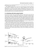
Figure 2.32 shows a schematic of the different types of materials, along with some
common materials employed in engineering practice. A brief discussion follows:
Metals and alloys have been employed extensively in engineering systems
because of their strength, toughness, and high electrical and thermal
conductivity. Availability, cost, and ease in processing to obtain a desired
nished product, through processes such as forming, casting, heat treat-
ment, welding, and machining, have contributed to the traditional popu-
larity of metals. A variety of metals have been employed in different
applications to satisfy their special requirements. Thus, copper has been
used for tubes because of its malleability, which allows easy bending,
and for electrical connections because of its high electrical conductivity.
Similarly, aluminum has been used for its low weight in airplanes and in
other transportation systems. Gold has been used in electronic circuitry
because of its resistance to corrosion. Alloys substantially expand the
Basic Considerations in Design 105
range of applicability of metals due to signicant changes achieved in
the properties. Steel, in its different compositions, is probably the most
versatile and widely used material in practical systems, from automo-
biles and trains to turbines and furnaces. Solder, which is an alloy of tin
and lead, is widely employed in electronic circuitry to make electrical
connections. Changes in its composition can be used to obtain different
strengths and melting points. For instance, a eutectic mixture of 63% tin
and 37% lead has a melting point of 183nC and a mixture of 10% tin
and 90% lead has a melting range of 275 to 302nC. Additions of silver
/&)'# ./##'
/&)'# ./##'
/&)'# ./##'
/&)'# ./##'
/&)'# ./##'
%-*(#./##'
- *)./##'
*)./)/)
$)'&0('0(&)0(''*3
*++#-''*3
-*)''*3
''*3.
&/
)&0(''*3
#/'.
0-#(#/'.
'0(&)0(
*++#-
-*)
#"
&)
&/)&0(
$.#"
#/'(/-&2
3'*)
*'3./3-#)#
5#-(*+'./&!
5#-(*.#/
*'3(#
'0&".
&,0&".
.#.
)#-/
!/&1#
/#-
&'.
'0*-*!- *).
& #-
'.#"
#-(&!.
*(+*.&/#.
/#-&'.
&)!
-
-*)4#
/&)'# ./##'
/%#-/#-&'.
#(&!*)"0!/*-(/#-&'&#.
**"!*)!-#/#
!#(#)/"&(*)"*/%#
FIGURE 2.32 Different types of materials used in engineering systems.
106 Design and Optimization of Thermal Systems
also affect the melting point and other properties, as discussed by Dally
(1990). Similarly, other alloys such as brass, inconel, nichrome, and tita-
nium alloys are used in different applications.
Ceramics, which are generally formed by fusing powders, such as those
of aluminum oxide (Al
2
O
3
), beryllium oxide (BeO), and silicon carbide
(SiC), under high pressure and temperature, have many characteristics
that have led to their increased usage in recent years. These include high
temperature resistance, low electrical conductivity, low weight, hardness,
corrosion resistance, and strength, though they are generally brittle. They
have a relatively low thermal resistance, as compared to other electrical
insulators. Consequently, ceramics are extensively employed in elec-
tronic circuitry, particularly in circuit boards. They are also used in high
temperature and corrosive environments, as tool and die materials, and
in engine components. Ceramics also include glasses as a subdivision
and these have their own range of applications due to transparency. The
optical ber is a recent addition to this group of materials, with applica-
tions in telecommunications, sensors, measurements, and controls. Vari-
ous other optical materials used in TV screens, optical networks, lasers,
and biosensors are also of considerable interest to industry.
Polymers, which include plastics, rubbers or elastomers, bers, and coatings,
have the advantages of easy fabrication, low weight, electrical insulation,
resistance to corrosion, durability, low cost, and a wide range of properties
with different polymers. Consequently, plastics have replaced metals and
alloys in a wide range of applications. Because these materials are electri-
cally insulating, they nd use in plastic-coated cables, plastic casings for
electronic equipment, and electrical components and circuitry. Similarly,
the ease of forming or molding polymeric materials has led to their use in
many diverse areas ranging from containers, trays, and bottles to panels,
calculators, and insulation. Clearly, polymers are among the most versa-
tile materials today, despite the temperatures that can be withstood by
them without damage being limited to 200 to 300nC in most cases.
Composite materials, which are engineered materials formed as combina-
tions of two or more constituent materials usually consisting of a rein-
forcing agent and a binder, have grown in importance in the last two
decades. The component materials generally have signicantly different
mechanical properties and remain separate and distinct within the nal
structure. Many naturally occurring materials such as wood, bone, and
muscle are composite materials. Therefore, many biological implants
are made of appropriate composite materials. The demand for materi-
als with high strength-to-weight ratio has led to tremendous advance-
ments in this eld. The reinforcing elements are largely bers of glass,
carbon, ceramic, metal, boron, or organic materials. The base or matrix
material is usually a polymer, metal, or ceramic. Chemical bonding is
generally used to bind the different elements to obtain a region that may
be regarded as a continuum. Different techniques are available for the
Basic Considerations in Design 107
fabrication of composite materials, as discussed by Hull (1981) and Luce
(1988). The main advantage of composite materials is that they can often
be custom-made for a particular design need. In addition, they have low
weight and high stiffness, strength, and fatigue resistance. They are
used for helicopter rotor blades, car body moldings, pressure vessels,
glass-reinforced plastics, concrete, asphalt, printed circuit boards, bone
replacements, and many other applications.
Liquids and gases are of particular interest in thermal processes because
uid ow is commonly encountered in many thermal systems. Gases
such as inert gases, oxygen, air, carbon dioxide, and water vapor are fre-
quently part of the system and affect the transport processes. Similarly,
liquids such as water, oils, hydrocarbons, and mercury (which is also
a metal) are employed in thermal systems for heat transfer, material
ow, pressure transmission, and lubrication. In addition, in many cases,
materials that are solid at normal temperatures are employed in their
molten or liquid state, for instance, plastics in extrusion and injection
molding, metals in casting, and liquid metals in nuclear reactors. The
ow characteristics of the uid, as indicated by its viscosity; thermal
properties, particularly the thermal conductivity; availability and cost;
corrosive behavior; and phase change characteristics vary substantially
from one uid to another and usually form the basis for selecting an
appropriate material.
Semiconductor and other materials. These include elements like silicon
and germanium, compounds like gallium arsenide and gallium phos-
phide, and several other similar materials that are often termed semicon-
ductor materials because they are neither good electrical conductors nor
good electrical insulators. They are used extensively in electronic sys-
tems because they have the appropriate properties to develop electronic
devices like transistors and integrated circuits, which are obviously of
tremendous importance and value today. Diamond, which is pure car-
bon, may also be included here. Several other materials of engineering
interest are not covered by the groups given earlier. These include mate-
rials like different types of wood, stone, rock, and other naturally occur-
ring materials that are of interest in various applications.
Therefore, the six main categories of materials are metals and alloys, ceramics,
polymers, composite materials, uids, and semiconductor materials. Each group
has its own characteristics. Some were just mentioned; see also Table 2.1. The
range of application of each type of material is determined by the physical charac-
teristics and the cost. New materials in each category are continually being devel-
oped to meet the demand for specic properties and characteristics and to improve
existing materials in a variety of applications. Substantial research and develop-
ment effort is directed at obtaining new and improved materials for enhancing the
performance of present systems, reducing costs, and helping future technological
advancements. Materials may also be categorized in terms of their applications,
108 Design and Optimization of Thermal Systems
for instance, electronic, insulation, construction, optical, and magnetic materials.
However, it is more common and useful to discuss materials in terms of their basic
characteristics and to use the six classes of materials outlined above.
2.5.2 MATERIAL PROPERTIES AND CHARACTERISTICS FOR THERMAL SYSTEMS
We have discussed different types of materials, their general properties, and typi-
cal areas of application. Though most of the properties mentioned earlier are
of interest in engineering systems, let us now focus on thermal processes and
systems. Obviously, many material properties are of particular interest in thermal
systems; for instance, a low thermal conductivity is desirable for insulation and
a high thermal conductivity is desirable for heat removal. A large thermal capac-
ity, which is the product of density and specic heat, is needed if a slow transient
response is desired and a small thermal capacity is necessary for a fast response.
The material properties that are of particular importance in thermal systems,
along with their usual symbolic representation employed in this book, are:
TABLE 2.1
Typical Characteristics of Common Materials
Metals and Alloys Ceramics Polymers
Strong Strong Weak
Tough Brittle Durable
Stiff Stiff Compliant
High electrical conductivity Electrically insulating Electrically insulating
High thermal conductivity Low thermal conductivity Low thermal conductivity
Easy processing Difcult processing Easy fabrication
Susceptible to corrosion Corrosion resistance Corrosion resistance
Easily available Light weight Low cost
Temperature resistance Temperature sensitive
Composites Liquids and Gases Semiconductor Materials
Strong Material ows Specialized characteristics
Fatigue resistant Inert or corrosive Not good electrical conductor
Stiff Wide range of properties Not good electrical insulator
Range of electrical
conductivity
Low electrical conductivity Electrical insulator at low
temperatures
Range of thermal
conductivity
Low thermal conductivity Electronic properties altered by
doping
Versatile Versatile Wide range of other properties
Low weight Generally low weight
Low cost Generally low cost
Basic Considerations in Design 109
1. Thermal conductivity, k
2. Specic heat, C
3. Density, R
4. Viscosity, M
5. Latent heat during phase change, h
sl
or h
fg
6. Temperature for phase change, T
mp
or T
bp
7. Coefcient of volumetric thermal expansion, B
8. Mass diffusivity, D
AB
Here, the subscripts sl, fg, mp, bp, and AB refer to solid-liquid, liquid-vapor, melt-
ing point, boiling point, and species A diffusing into species B, respectively. The
phase change may occur over a range of temperatures, which is the case for an
alloy or a mixture. The specic heat may be at constant pressure or at constant
volume, these being essentially the same for solids and liquids, which may gen-
erally be taken as incompressible. Several other thermal properties such as the
coefcient of linear thermal expansion, heat of sublimation, and thermal-shock
resistance are also of interest in thermal systems.
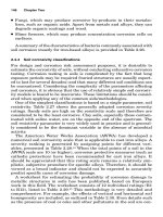
All these properties vary tremendously among the common materials used
in thermal processes. For instance, the thermal conductivity varies from around
0.026 for air to 0.61 for water to 429.0 W/mK for silver. Typical ranges are
shown in Figure 2.33. Similarly, other properties are available in the literature
(Touloukian and Ho, 1972; American Society of Metals, 1961; ASHRAE, 1981;
Eckert and Drake, 1972; Incropera and Dewitt, 2001). In addition, properties such
as thermal diffusivity A, where Ak/RC, and kinematic viscosity N, where NM/R,
are also frequently used to characterize the material. Many common materials
and their properties are given in Appendix B.
In addition to the aforementioned thermal properties of the material, several
characteristics discussed in the preceding section are important in the design of
0!*)#"(
)'+
$&+
*)(
!$)/$!"
,"*
"* -*0
"
/$!"+
&-'$(-'
$(
$&."*
$ %"&
&+,$ +
$"*+
1"*'& )(!- ,$.$,0'2
FIGURE 2.33 Range of thermal conductivity k for a variety of materials under normal
temperature and pressure.
110 Design and Optimization of Thermal Systems
thermal systems. Certainly, corrosion resistance and range of temperature over which
the material can be used are important considerations. Similarly, strength, toughness,
stiffness, and others, are important in the design because of the need to maintain
the structural integrity of the system. Material cost and availability are obviously
important in any design process. Manufacturability of the material is also important,
as mentioned earlier. Waste disposal and environmental impact of the material are
additional considerations in the characterization and evaluation of the material.
2.5.3 SELECTION AND SUBSTITUTION OF MATERIALS
In view of the material properties and characteristics discussed in the preceding
section, the factors involved in the selection of a suitable material in the design of
a thermal system are:
1. Satisfactory thermal properties
2. Manufacturability
3. Static, fatigue, and fracture characteristics
4. Availability
5. Cost
6. Resistance to temperature and corrosion
7. Environmental effects
8. Electric, magnetic, chemical, and other properties
Material selection is not an easy process because of the many considerations
that need to be taken into account. These lead to a variety of constraints, many of
which may be conicting. Though cost is an important parameter in the selection,
it is not the only one. We want to choose the best material for a given application
while satisfying many constraints. However, information on material properties
is often not available to the desired detail or accuracy. The range of available
materials has increased tremendously in recent years, making material selection
a very involved process. However, the choice of the most appropriate material for
a given application is crucial to the success of the design in today’s internationally
competitive environment. With a proper choice of materials, the system perfor-
mance can be improved and costs reduced. In several cases, material substitution
is needed because of regulations stemming from environmental or safety con-
siderations. For example, the incentive for improvements in gasoline, including
addition of ethanol, arises from pollution, availability, cost, and political consid-
erations. Substitution of asbestos by other insulating materials is due to the health
risks of asbestos. Obviously, all such considerations complicate material selection
and substantial effort is generally directed at this aspect of design.
The basic procedure for material selection may be described in terms of the
following steps.
1. Determination of material requirements. The thermal process or sys-
tem being designed is considered to determine the conditions and
environment that the chosen material must withstand. From this consid-
eration, the desired properties and characteristics, along with possible
Basic Considerations in Design 111
constraints, are obtained. For example, the simulation of a furnace would
indicate the temperatures that the materials exposed to this environment
must endure. Similarly, the expected pressures in an extruder would
provide the corresponding requirements for the selected material.
2. Consideration of available materials. Material property databases are
available and may be employed to compare the material requirements
with the properties of obtainable materials. In such a search, the focus is
on the desired properties and characteristics. The requirements in terms
of thermal properties will be largely considered at this stage for thermal
processes. Cost, environmental effects, and other considerations and
constraints are not brought in. Therefore, a large number of material
choices may emerge from this step. This is done mainly to avoid elimi-
nating any material that meets the appropriate requirements.
3. Selecting a group of possible materials. From the materials that would
satisfy the main requirements of the application, a smaller group is cho-
sen for a more detailed consideration. At this stage, other considerations
and constraints are brought in. Thus, a material that is very desirable due
to its thermal properties may be eliminated because of cost or undesirable
environmental impact. Gold, which is a good choice for electronic circuit
elements because of its inert nature, is retained only for surface plating
due to the cost. Manufacturability of the material to obtain a given part is
also an important consideration at this stage. Information on previously
used materials for the given problem and for similar systems may also be
used to narrow the list of possible materials. Since there may be several
requirements for the material properties, a weighted index that takes all
of these into account, according to their relative importance, may also be
employed. A short list of possible materials is thus obtained.
4. Study of material performance. A detailed study of the materials
obtained from the preceding step is undertaken to determine their per-
formance under the specic conditions expected to be encountered in the
given application. Experimental work may also be carried out to obtain
quantitative data and to characterize these materials. Available literature
on these materials and information on their earlier use in similar envi-
ronments are also employed. There are many standard sources for mate-
rial property data (Dieter, 2000); some of them were mentioned earlier.
5. Selection of best material. Based on the information gathered on the
short list of possible materials, the most appropriate material for the
given application is chosen. The cost and availability of the material
are very important considerations in the nal selection. However, there
are many cases where cost may have to be sacriced in the interest of
superior performance. In a few cases, the material may be developed to
meet the specic needs of the problem. This is true in many electronic
systems where the materials employed for the circuit board, the cir-
cuitry, and the connections are developed as variations from existing
composite materials, ceramics, solder, etc. (Dally, 1990).
112 Design and Optimization of Thermal Systems
Final Comments
Material selection is an involved process and is somewhat similar to the iterative
design process discussed earlier for thermal systems. Several options are con-
sidered and the best one is chosen based on available property data and material
characteristics. Expert systems may also be used to help in this selection process
by bringing in existing expert knowledge on materials and information on cur-
rent practice. Then the decision-making process may be automated by using a
large database on available materials and their characteristics. In many cases, an
existing process or system is to be improved by substituting the current material
for a different material. In several applications, plastics, ceramics, and composite
materials have recently replaced metals and alloys. Plastics are now used for most
containers and housings because of lower weight and cost involved. Similarly,
composite materials lead to improvements over metals in many of their important
characteristics, while keeping the cost lower. Thus, substantial improvements in
system performance and reduction in costs are obtained by material substitution.
However, redesign of the component, subsystem, or system should be undertaken
to obtain the maximum benet from material substitution.
E 2.7
(a) In a food processing system, food materials are placed on at plates that are
attached to and moved continuously by a conveyor belt. The food is subjected
to gas heating at the bottom of the plate for a given amount of time. Select a
suitable material for the plates.
(b) Select suitable materials for an electronic system, considering the board on
which electronic components are located and electrical connections between
these components by means of exposed circuitry on the board.
Solution
(a) In this problem, a high thermal conductivity material is desirable because
of heat conduction through it to the food material. In addition, the material
must be strong, durable, and corrosion resistant because of the application.
Table 2.1 indicates that metals and alloys would satisfy these requirements.
Ceramics have lower conductivity and may be too brittle for this applica-
tion. Though copper and aluminum have high thermal conductivities (401
and 237 W/mK, respectively, at 300 K), alloys such as bronze and brass are
easier to form into the desired shape and to bond to the conveyor. But then the
conductivities are much smaller (around 50 W/mK). Steel is a better choice
because of better corrosion resistance and cost. Stainless steel can be chosen
due to its high corrosion resistance, but it is a difcult material to work with
for fabrication, it is relatively expensive, and it has a lower thermal conductiv-
ity (approximately 15 W/mK). Carbon steels are cheaper, easier to form, and
better conductors of heat (thermal conductivity around 60 W/mK).
In view of the above considerations, carbon steel may be chosen as the appro-
priate material, with the exact percentage of carbon chosen based on cost and
availability. Since food is involved, a nonstick surface is desirable. A Teon
coating on the surface can be used for this purpose.
Basic Considerations in Design 113
(b) For the electrical connections, a high electrical conductivity is needed, point-
ing to metals. Ceramics and polymers are electrical insulators and composites
are generally not good conductors. Silver, copper, gold, and aluminum are
very good electrical conductors, with conductivities of 6.8, 6.0, 4.3, and 3.8 r
10
7
(ohm-m)
1
. Aluminum is useful if weight considerations are important.
However, copper is a very good choice because it is relatively cheap and easy
to form and bond to obtain the desired conguration of the electrical circuitry.
Its melting point is high (1358 K). However, it does not have good corrosion
resistance and may cause problems if the system is to be used under humid
conditions. Gold is excellent in corrosion resistance, is a good conductor, and
has a high melting point (1336 K). However, it is much more expensive than
copper and is hard to bond to other metals. Therefore, the electrical circuitry
connections may be made of copper with gold plating used for corrosion resis-
tance. Silver plating may also be used, but it is not as corrosion resistant and
durable as gold.
For the board material, on the other hand, we need an electrical insulator.
It must be strong enough to support the circuitry and components. There-
fore, polymers, ceramics, or composites may be used. However, ceramics are
brittle and relatively difcult to machine. Polymers are good for the purpose,
but they may be too exible unless thick plates are used. Composite materials
are a good choice because these could be reinforced with metal or glass bers
to obtain the desired strength. The other properties could also be varied by
the choice of the structure of the material. Therefore, a variety of composite
materials may be chosen for the purpose.
Clearly, several other material options are possible for these applications and
a unique answer is rarely obtained. However, these examples indicate the initial
selection of the type of material, narrowing of the available choices, and nal selec-
tion of an appropriate material.
2.6 SUMMARY
This chapter presents the basic features of design of thermal systems. Several
important concepts and ideas are introduced and discussed in terms of typical
thermal processes.
The formulation of the design problem is the rst step in design; the entire
process and the success of the nal design depend on the basic problem statement.
The formulation involves determining the requirements of the system; parameters
that are given and are thus xed; design variables that may be changed in order
to seek an acceptable or workable system; any constraints or limitations that must
be met; and any additional considerations arising from safety, environmental,
nancial, and other concerns. The nal design must satisfy all the requirements
and must not violate any of the constraints imposed on the system, its parts, or
the materials involved. It is important to formulate the design problem in clear
and quantitative terms, while focusing on the important features of the design
and neglecting minor ones because it may be difcult or impossible to solve the
problem if every possible requirement and constraint is to be satised.
114 Design and Optimization of Thermal Systems
Conceptual design is the next step in the design of a thermal system to meet a
given need or opportunity. Originality and creativity are expressed in the form of
the basic concept or idea for the design. The conguration and main features of the
thermal system are given in general terms to indicate how the requirements and
constraints of the given problem will be met. The conceptual design may range from
a new, innovative idea to available concepts applied to similar problems and modi-
cations in existing systems. Many conceptual designs are based on available designs
and concepts, incorporating new materials and techniques developed in the industry.
Knowledge of current technology, existing systems and processes, and advances in
the recent past is a strong component in the development of appropriate conceptual
designs. Usually, several concepts are considered and evaluated for a given applica-
tion, and the one that has the best chance of success is ultimately chosen.
The selected conceptual design leads to an initial physical system that is sub-
jected to the detailed design process, starting with the modeling and simulation of
the system. Modeling involves simplifying and approximating the given process
or system to allow a mathematical or numerical solution to be obtained. However,
it must be an accurate and valid representation of the physical system so that the
behavior of the system may be investigated under a variety of conditions by using the
model. Modeling of thermal systems is an extremely important aspect in the design
process because most of the inputs needed for design and optimization are obtained
from a numerical simulation of the model. Experimental results, material property
data, and information on the characteristics of various devices are also incorporated
in the overall model to obtain realistic and practical results from the simulation.
The outputs from the simulation are used to determine if the design satises
the requirements and constraints of the given problem. If it does, an acceptable
or workable design is obtained. Several such acceptable designs may be sought to
establish a domain from which the best or optimal design is determined. Though
several designs may be acceptable, the best design, optimized with respect to a
chosen criterion, is essentially unique or may be selected from a narrow region of
design variables. In many cases, multiple objective functions are of interest and
the optimization strategy must consider these. The need for optimization of ther-
mal systems has grown tremendously in recent years due to international compe-
tition. Additional aspects such as safety and control of the system, environmental
issues, and communication of the design are also discussed.
The basic features of a CAD system are also outlined. Such a system
involves interactive use of a stand-alone computer to help the design process
by providing results from the simulation of the system being designed. Storage
of relevant information, graphical display of results, and knowledge base from
current engineering practice, including rules for decision-making, add to the
usefulness of a CAD system. However, because of the complexity of typical
thermal systems and processes, such CAD systems are often limited to the
design of relatively simple systems and equipment.
Finally, the important aspect of material selection is considered in this chap-
ter. The crucial part played by materials in the design of thermal systems cannot
be exaggerated because the success of a design is strongly affected by the choice
Basic Considerations in Design 115
of suitable materials for the various parts of the system. With the advent of new
materials, particularly ceramics and composite materials, it is essential that we
seek out the most appropriate material for each application. Substitution of cur-
rently used materials by new and improved ones is also undertaken to improve the
system performance and reduce costs. However, redesign of the system must gen-
erally be undertaken when material substitution is considered in order to obtain
maximum benet from such a substitution. Different types of materials and the
basic procedure for material selection are presented.
REFERENCES
Alger, J.R.M. and Hays, C.V. (1964) Creative Synthesis in Design, Prentice-Hall, Engle-
wood Cliffs, NJ.
American Society of Heating, Refrigeration and Air Conditioning Engineers (1981)
ASHRAE Handbook of Fundamentals, ASHRAE, New York.
American Society of Metals (1961) Metals Handbook, American Society of Metals,
Metals Park, OH.
Burge, D.A. (1984) Patents and Trademark Tactics and Practice, 2nd ed., Wiley, New York.
Cengel, Y.A. and Boles, M.A. (2002) Thermodynamics: An Engineering Approach, 4th
ed., McGraw-Hill, New York.
Dally, J.W. (1990) Packaging of Electronic Systems: A Mechanical Engineering Approach,
McGraw-Hill, New York.
Dieter, G.E. (2000) Engineering Design: A Materials and Processing Approach, 3rd ed.,
McGraw-Hill, New York.
Eckert, E.R.G. and Drake, R.M. (1972) Analysis of Heat and Mass Transfer, McGraw-Hill,
New York.
Figliola, R.S. and Beasley, D.E. (1995) Theory and Design for Mechanical Measurements,
2nd ed., Wiley, New York.
Howell, J.R. and Buckius, R.O. (1992) Fundamentals of Engineering Thermodynamics,
2nd ed., McGraw-Hill, New York.
Hull, D. (1981) An Introduction to Composite Materials, Cambridge University Press,
Cambridge, U.K.
Incropera, F.P. and Dewitt, D.P. (2001) Fundamentals of Heat and Mass Transfer, 5th ed.,
Wiley, New York.
Jaluria, Y. and Lombardi, D. (1991) Use of expert systems in the design of thermal equip-
ment and processes, Res. Eng. Design, 2, 239–253.
Luce, S. (1988) Introduction to Composite Technology, Society of Manufacturing Engi-
neers, De arborn, MI.
Lumsdaine, E. and Lumsdaine, M. (1995) Creative Problem Solving 3rd ed., McGraw-
Hill, New York.
Moore, F.K. and Jaluria, Y., (1972) Thermal effects of power plants on lakes, ASME J.
Heat Transfer, 94, 163–168.
Moran, M.J. and Shapiro, H.N. (2000) Fundamentals of Engineering Thermodynamics,
4th ed., Wiley, New York.
Palm, W.J. (1986) Control Systems Engineering, Wiley, New York.
Patankar, S.V. (1980) Numerical Heat Transfer and Fluid Flow, Taylor & Francis,
Washington, D.C.
Pressman, D. (1979) Patent it Yourself? How to Protect, Patent and Market Your Inven-
tions, McGraw-Hill, New York.
116 Design and Optimization of Thermal Systems
Raven, F.H. (1987) Automatic Control Engineering, 4th ed., McGraw-Hill, New York.
Reddy, J.N. (1993) An Introduction to the Finite Element Method, 2nd ed., McGraw-Hill,
New York.
Tadmor, Z. and Gogos, C.G. (1979) Principles of Polymer Processing, Wiley, New York.
Touloukian, Y.S. and Ho, C.Y., Eds. (1972) Thermophysical Properties of Matter, Plenum
Press, New York.
Zienkiewicz, O. (1977) The Finite Element Method, 3rd ed., McGraw-Hill, New York.
PROBLEMS
Note: All the questions given here are open-ended. Thus, some inputs and
approximations may need to be supplied by you and several acceptable solutions
are possible. Appropriate literature may be consulted for these problems as well
as for similar open-ended problems in later chapters.
2.1. In the Czochralski crystal growing process, a solid cylindrical crystal
is grown from a rotating melt region, as shown in Figure P2.1. We
are interested in obtaining a homogeneous cylinder of high purity of
a given material such as silicon and with a uniform specied diam-
eter. For this manufacturing process, list the important inputs, require-
ments, and design specications needed to design the system. Also,
give the design variables and constraints, if any.
Czochralski crystal growing
D
Solid-liquid
interface
Melt
d
U
Solid crystal
Inert
gas flow
Crucible
ω
FIGURE P2.1
Basic Considerations in Design 117
2.2. For a continuous casting system, shown in Figure 1.10(a), formulate
the design problem in terms of given quantities, design variables, and
constraints, employing symbols for the dimensions, temperatures, and
other physical quantities. We wish to obtain a casting of given diameter
for the chosen material.
2.3. Give the design variables and operating conditions for the following
manufacturing processes:
(a) Ingot casting
(b) Plastic extrusion
(c) Hot rolling
2.4. Cooling towers, as shown in Figure 1.14(b), are to be designed for heat
rejection from a power plant. The rate of heat rejection to a single tower
is given as 200 MW. Ambient air at temperature 15°C and relative
humidity 0.4 are to be used for removal of heat from the hot water
coming from the condensers of the power plant. The temperature of the
hot water is 20°C above the ambient temperature. Give the formulation
of the design problem in terms of the xed quantities, requirements,
constraints, and design variables.
2.5. The condensers of a 500 MW power plant operating at a thermal ef-
ciency of 30% are to be cooled by the water from a nearby lake, as
sketched in Figure 1.14(a). If the intake water is available at 20°C and
if the temperature of the water discharged back into the lake must be
less than 32°C, quantify the design problem for the cooling system.
How is the net energy removed from the condensers nally lost to the
environment?
2.6. Formulate the design problem for the following manufacturing pro-
cesses, employing symbols for appropriate physical quantities.
(a) Hot rolling of a steel plate of thickness 2 cm to reduce the thick-
ness to 1 cm at a feed rate of 1 m/s; see Figure 1.10(d).
(b) Solder plating of a 2-mm-thick epoxy electronic circuit board by
moving it across a solder wave at 350nC, the solder melting point
being 275nC. See Figure P2.6(b)
Molten
solder
Bo
ard
U
FIGURE P2.6(b)
118 Design and Optimization of Thermal Systems
(c) Extrusion of aluminum from a heated cylindrical block, of diam-
eter 15 cm at a temperature of 600 K, to a rod of diameter 5 cm at
the rate of 0.2 cm/s. See Figure P2.6(c).
(d) Arc welding by means of an electrode moving at 5 cm/s and sup-
plying 1000 W to join two metal plates, each of thickness 5 mm.
See Figure P2.6(d)
2.7. A system for the storage of thermal energy is to be designed using an
underground tank of water. The tank is buried at a depth of 3 m and is a
cube of 1 m on each side. The water in the tank is heated by circulating
it through a solar energy collection system. A given heat input to the
water may be assumed due to the solar energy ux. Characterize the
design problem in terms of the xed quantities and design variables.
2.8. Consider a typical water cooler for drinking water. If the water intake
on a summer day is at 40°C and the cooler must supply drinking water
in the range of 14 to 21°C at a maximum ow rate of 1 gallon/min
(3.785 r 10
3
m
3
/min), give the requirements for the design. Also, choose
an appropriate conceptual design and suggest the relevant design vari-
ables and constraints.
dUD
FIGURE P2.6(c)
FIGURE P2.6(
d)
Plates
Arc
Welding
rod
Basic Considerations in Design 119
2.9. For the plastic extrusion system considered in Example 2.1, formu-
late the design problem in terms of quantities that would generally be
given, quantities that may be varied to obtain an acceptable design, and
possible design requirements and constraints
2.10. Coal for a steel plant is delivered by train at a station that is 10 km
from the storage units of the plant. List different ways of transport-
ing the coal from the station to the storage units and discuss the pos-
sible advantages and disadvantages of each approach. Choose the most
appropriate system, giving reasons for your choice. Take the typical
daily consumption of coal to be 10
4
kg.
2.11. Water from a purication plant is to be stored in a tank that is located
at a height of 100 m and supplies the water needed by a chemical
factory. Develop different conceptual designs for achieving this task
and choose the most suitable one, justifying your choice. The average
consumption of water by the factory may be taken as 1000 gallons/h
(3.785 m
3
/h).
2.12. For the following tasks, consider different design concepts that may
be used to achieve the desired goals. Compare the different options in
terms of their positive and negative features. Then narrow your deliber-
ations to one concept. Sketch the conceptual design thus obtained and
give qualitative reasoning for your choice. Remember that the design
chosen by you may not be the only feasible one.
(a) Scrap plastic pieces are to be melted and then solidied in the
form of cylindrical rods at a rate of about 20 kg/h.
(b) Solar energy collected by a at plate collector system is to be stored
to supply hot water at a temperature of 70 o 5nC to an industrial
unit.
(c) Water from a purication plant is to be transported to and stored
in a tank at a height of 5 m above the plant. A maximum ow rate
of 10 gallons/min (0.03785 m
3
/min) is desired.
(d) The water from a river is to be supplied at a ow rate of 50 gallons/
min and a pressure of 5 atm to a water treatment plant.
(e) A company wants to discharge its nontoxic chemical waste into a
river, with the smallest impact on the local water region, within 25
m of the discharge point.
(f) Food materials are to be frozen by reducing the temperature to
below –15nC. A net energy removal rate of 100 kW is desired.
(g) A building of oor area 500 m
2
is to be heated by circulating hot
air. The temperature of the air must not exceed 90nC.
2.13. For the following systems, discuss the nature, type, and possible loca-
tions of sensors that may be used for safety as well as for control of the
process.
(a) A water heating system consisting of a furnace, pump, inlet/outlet
ports, and piping network, as shown in Figure P2.13(a).
120 Design and Optimization of Thermal Systems
(b) A system to heat short metal rods in a gas furnace and then bend
these into desired shapes in a metal-forming process.
(c) Electronic circuitry for a mainframe computer.
(d) Cooling and fuel systems of a typical car.
(e) A forced-hot-air-ow oven for drying paper pulp, as shown in Fig-
ure P2.13(e).
2.14. For the air conditioning system considered in Example 2.2, discuss the
types and locations of sensors that may be employed for the safety and
control of the system.
2.15. Look up any patent in the literature. List the different parts of the pat-
ent and outline the information conveyed by such a document. How
does one ensure that the basic concept is protected and that a slight
change in the method is not treated as something new and not covered
by the patent?
2.16. Copyrighting of computer software is quite prevalent today because its
development is generally expensive. However, most details on the algo-
rithm are to be provided for copyrighting. Suggest a few approaches
that may be employed to avoid duplication and use of the software by
others without appropriate permission and licensing.
Gas heating
Furnace
Water inlet
Pump
Outlets
FIGURE P2.13(a)
Oven
AirFan
Heaters
Hot air
Paper pulp
conveyor
FIGURE P2.13(e)
Basic Considerations in Design 121
2.17. If a CAD system is envisaged for the design of HVAC (heating, ventila-
tion, and air conditioning) systems, what relevant characteristics would
be desirable? What should the different parts of the CAD system con-
tain? Are there some features that are crucial to the successful use of
the CAD approach for this problem?
2.18. Repeat the preceding problem for a power plant heat rejection system
consisting of condensers, circulating water, and cooling towers.
2.19. In view of the increasing speed and storage capacity of computer work-
stations, discuss what additional features could be included in the CAD
system outlined in Example 2.6 to make the system more versatile and
useful for practical processes.
2.20. Consider different materials that may be used for the following appli-
cations. Using the general characteristics of these materials, choose
the most appropriate one, giving reasons for the choice. The nal
material selected is not unique and several options may be possible.
Discuss your selection criteria. Remember to include cost, avail-
ability, and safety issues in your considerations of different material
choices.
(a) Outer casing for a personal computer.
(b) Material for the boards used in an electronic circuitry of a television.
(c) Materials for the tube and shell of a heat exchanger.
(d) The mold material for the casting of aluminum, as shown in
Figure 1.3 How will the material differ if steel were being cast
instead?
(e) Materials for the seats in an airplane. Are any thermal consider-
ations involved in the material selection?
(f) Electronic circuitry used in an airplane.
(g) Materials for the wall and the insulation of a gas furnace used for
melting scrap steel pieces.
(h) Liquid that may be used for immersion cooling of an electronic
system.
2.21. Consider the cooling systems for an automobile and for a personal
computer. Suggest various materials that may be employed, discussing
the differences between the two applications. Narrow your choices to
the best one or two candidates, giving reasons for this selection.
2.22. There are several subsystems in an automobile. List a few of these. Pick
any one thermal subsystem and, using your imagination and experi-
ence, give a set of requirements and constraints that must be satised
for a workable design. Also, give the design variables that you may be
able to select to obtain a successful design. Give a rough sketch of the
subsystem chosen by you and express the constraints, requirements,
etc., mathematically, as far as possible.
2.23. Let us assume that your design group, working in an industrial con-
cern, has completed the design of the following thermal systems, using