Design and Optimization of Thermal Systems Episode 2 Part 4 doc
Bạn đang xem bản rút gọn của tài liệu. Xem và tải ngay bản đầy đủ của tài liệu tại đây (238.61 KB, 25 trang )
Numerical Modeling and Simulation 297
may be coupled with the modeling of uid ow adjacent to the rod and
other parts of the system to complete the model of a given system.
4.43. Consider heat conduction in a two-dimensional, rectangular region of
length 0.3 m and width 0.1 m. The dimension in the direction normal
to this region may be taken as large. The dimensionless temperature
is given as 1.0 at one of the longer sides and as 0.0 at the others. Solve
the governing Laplace equation by the SOR method and determine
the optimum relaxation factor. Discuss how, in actual practice, such a
simulation may be linked with those for other parts of the system.
4.44. Consider the fan and duct system given in Example 4.7. Vary the zero-
ow pressure, given as 80 in the problem, and the zero-pressure ow
rate, given as 15 here, by o20%. Discuss the results obtained. Are they
consistent with the physical nature of the problem as represented by the
equations?
4.45. Show the information-ow diagram for Problem 4.18. Also, draw the
information-ow diagram for the simulation of Problem 4.35. Do not
solve the equations; just explain what approach you will use.
299
5
Acceptable Design
of a Thermal System:
A Synthesis of Different
Design Steps
5.1 INTRODUCTION
In the preceding chapters, we discussed the main aspects involved in the design
of a thermal system. An acceptable or satisfactory design must satisfy the given
requirements for the system and must not violate the limitations or constraints
imposed by the application, materials, safety, environmental effects, and other
practical considerations. At this stage, we are not concerned with the optimiza-
tion of the system and are largely interested in obtaining a feasible design. Though
any design that meets the given requirements and constraints may be adequate for
some applications, it is generally desirable to seek a domain of acceptable designs
from which an appropriate design is selected on the basis of cost, ease of fabrica-
tion, availability of materials, convenience in usage, etc.
The various considerations that are involved in the development of an accept-
able design of a thermal system have been discussed in Chapter 2. These led to
the following main steps:
1. Formulation of the design problem
2. Conceptual design
3. Initial design
4. Modeling of the system
5. Simulation of the system
6. Evaluation of the design
7. Selection of an acceptable design
Optimization of the design follows the determination of a domain of accept-
able designs and is not included here. Most of the other aspects, particularly prob-
lem formulation, conceptual design, modeling, and simulation, were discussed
in detail in the preceding chapters. The rst step in the foregoing list quanties
the design problem, and the second step provides the basic idea or concept to
achieve the desired goals. The remaining steps constitute what might be termed
as the detailed, quantitative design process, or simply the design process for
300 Design and Optimization of Thermal Systems
convenience. These steps analyze the design and ensure that the problem state-
ment is satised.
In this chapter, we will consider the synthesis of the different steps and stages
that constitute the design effort in order to obtain an acceptable design. Individual
aspects, such as modeling and simulation of thermal systems, which were dis-
cussed in detail earlier, will be considered as parts of the overall design strategy.
The main purpose of this chapter is to link the different aspects that are involved
in the design of a thermal system and to demonstrate the design procedure, start-
ing with the problem formulation, proceeding through modeling and simulation,
and ending with an acceptable design. Examples are employed to illustrate this
coupling.
Several diverse thermal systems, ranging from those in materials processing
to those in energy and environmental systems, were considered in the previous
chapters. It has been shown that the basic concerns, modeling, simulation, and
system characteristics, vary signicantly from one class of systems to another.
For instance, lumped steady-state modeling is usually adequate for refrigeration
and air-conditioning systems, leading to algebraic equations, whereas distributed
time-dependent modeling is generally needed for manufacturing processes and
electronic equipment cooling, resulting in partial differential equations. Con-
sequently, the simulation procedures vary with the type of system under con-
sideration. The design strategy itself may be affected by these considerations.
Therefore, examples of thermal systems from different application areas are con-
sidered in this chapter and the corresponding design strategies presented. The
systems considered range from relatively simple ones to fairly complicated ones
in order to demonstrate the applicability of the basic ideas to the design of a wide
variety of systems.
Before proceeding to the complete design process for typical thermal sys-
tems, an aspect that needs more detailed consideration is that of initial design.
In many cases, the initial design is reached by considering the requirements and
constraints of the problem and choosing the design variables, through approxi-
mate analysis and estimates, so that these satisfy the given problem statement. If
different components are to be chosen and assembled for a thermal system, the
choice of these components is guided by the requirements and constraints, so
that the initial design is itself an acceptable design. Though redesign is obviously
needed in case the initial design is not acceptable, it is important to employ the
best possible initial design so that it is either acceptable by itself or the number of
redesigns needed to converge to an acceptable design is small.
5.2 INITIAL DESIGN
The search for an initial design follows the formulation of the problem and the
conceptual design. It is thus the rst step in the quantitative design procedure.
The analysis of the system, through modeling and simulation, and evaluation
of the design for its acceptability are based on the initial design. The initial,
starting design affects the convergence of the iterative design process and often
Acceptable Design of a Thermal System 301
even inuences the nal acceptable or optimal design obtained. Therefore, the
development of an initial design is a critical step in the design procedure, and
considerable care and effort must be exerted to obtain a design that is acceptable
or as close as possible to an acceptable design.
Ideally, the design variables should be selected so that the initial design sat-
ises the given requirements and constraints. Unfortunately, this is usually not
possible for thermal systems because analysis only yields the outputs on system
behavior for given inputs, rather than solve the inverse problem of yielding the
inputs needed for a desired behavior. If the outputs and inputs were connected by
simple relationships that could be inverted to obtain the inputs for required out-
puts, the problem would be considerably simplied. However, thermal systems
usually involve complexities arising from nonlinear mechanisms, partial differ-
ential equations, coupled phenomena, and other complications, as discussed in
Chapter 1. This makes it very difcult to solve the inverse problem in order to
select the design variables, in an initial design, to satisfy all the requirements and
constraints. Consequently, iteration is generally necessary to obtain a satisfac-
tory design.
Several approaches may be adopted in the selection or development of the
initial design. The approach that is appropriate for a given problem is a function
of the nature of the thermal system under consideration, information available on
previous design work, and the scope of the design effort. Some of the commonly
used methods for obtaining an initial design are
1. Selection of components to meet given requirements and constraints
2. Use of existing systems
3. Selection from a library of previous designs
4. Use of current engineering practice and expert knowledge of the appli-
cation
Selection of Components
In general, a combination of all the approaches given above is used to come up
with the best initial design for practical thermal systems. However, each of these
may also independently yield the desired starting point for iterative design. Selec-
tion of components is particularly valuable in thermodynamic systems, such as
refrigeration, air conditioning, and heating systems, where the design of the over-
all system generally involves selecting the different components to meet the given
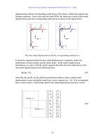
requirements or specications. An example of this is the air-cycle refrigeration
system, based on the reverse Brayton cycle and shown in Figure 5.1, which is
commonly used aboard jet aircrafts to cool the cabin. The turbine, the compres-
sor, and the heat exchanger may be selected based on the desired temperature and
pressure in the cabin, along with the thermal load, to obtain an initial design.
An analysis of the thermodynamic cycle shown yields the appropriate speci-
cations of the components for an ideal cycle or for a real one with given isentropic
efciencies (Reynolds and Perkins, 1977; Howell and Buckius, 1992). For an ideal
302 Design and Optimization of Thermal Systems
Work
Turbine
Compre-
ssor
P
H
32a
1
4a
Heat
exchanger
Heat
exchanger
Heat rejected
(a)
P
L
P
H
P
L
3
Temperature
Heat input
Heat rejected
1
Compressor
Actual
2a
2s
4s
4a
Turbine
Actual
Entropy
(b)
Heat input
FIGURE 5.1 The hardware and the thermodynamic cycle, with real, nonideal compressor
and turbine, for the Brayton cycle.
Acceptable Design of a Thermal System 303
cycle, the efciency H, which is the ratio of the work done to the energy input into
the system, is given by the expression
H
G
G
¤
¦
¥
³
µ
´
1
1
1
P
P
H
L
(5.1)
where G is the ratio of the specic heat at constant pressure C
p
to that at constant
volume C
v
, and P
H
, P
L
are the high and low pressures in the system, respectively.
The corresponding temperatures can be calculated for isentropic processes and
then for a real, nonideal system using the efciencies. Any constraints on pres-
sures or temperatures given in the problem can be taken care of by a proper choice
of these components. A given range of desired efciency for satisfactory systems
may also be taken as a requirement. Therefore, the initial design itself satises
the problem statement and is an acceptable design. This design may be modeled
and simulated to study the system behavior under different operating conditions
to ensure satisfactory performance in practical use. Example 5.1 and Example 5.2
discuss this approach for thermodynamic systems.
Existing Systems
The development of an initial design based on existing systems for applications
similar to the one under consideration is a very useful technique. Unless a com-
pletely new concept is being considered for the given application, systems that
perform similar, though different, tasks are usually available and in use. For
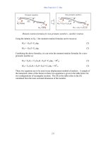
instance, if a forced-air furnace is being designed for continuous heat treatment of
silicon wafers as a step in the manufacture of semiconductor devices, as shown in
Figure 5.2, similar systems that are being used for other processes, such as baking
of circuit boards and curing of plastic components, may be employed to obtain
initial estimates of the heater characteristics, wall material and dimensions, con-
veyor design, interior dimensions, etc. This provides the starting point for the
iterative design-redesign process, which varies the relevant design variables to
arrive at an acceptable design.
Conveyor
Heaters
Silicon wafers
FIGURE 5.2 A thermal system for the heat treatment of silicon wafers in the manufacture
of electronic circuitry.
304 Design and Optimization of Thermal Systems
Library of Previous Designs
Any industry involved with the design of systems and equipment would generally
develop many successful designs over a period of time for a variety of applica-
tions and design specications. Even for the design of a particular system, several
designs are usually generated during the process to obtain the best or optimal
design. Consequently, a library of previous successful designs can be built up for
future use. Note that these designs may not have been translated into actual physi-
cal systems and may have remained as possible designs for the given application.
Such a library provides a very useful source of information for the selection of an
initial design. For instance, an effort on the design of heat exchangers would give
rise to many designs that may not be chosen for fabrication because they were not
the optimum or because they did not meet the requirements for a given applica-
tion. However, for different design specications, some of the earlier designs that
were discarded might be satisfactory. Similarly, the design of an air compressor
may yield many designs that are discarded because the pressure or the ow rate
is too low. However, if this information is retained, it can be used for selecting
an initial design for some other applications. Therefore, considerable effort is
saved in the development of the initial design if such a library of earlier designs,
along with their specications, is available. As soon as a new design problem is
initiated, the library may be employed to obtain a design with outputs as close as
possible to the given requirements. For instance, if the total rate of heat transfer
desired from the heat exchanger is given, a design that gives the closest heat trans-
fer rate is chosen from the design library. This approach is particularly suitable
for equipment, such as heat exchangers, heat pumps, boilers, and refrigerators.
Expert Knowledge
The last approach for developing an initial design is based on information avail-
able on the particular application and corresponding types of thermal systems,
along with current engineering practice. Such an approach is very hard to quan-
tify because the available information is often vague and may not have a solid
analytical foundation. This is what is often termed as expert knowledge, i.e., the
information obtained from an expert in the area. Several ideas developed over
the years form the basis for such knowledge and play a major role in determining
what is feasible. Information from earlier problems and attempts to resolve them
is also part of this knowledge. Many aspects in thermal systems are very dif-
cult to analyze or measure, such as contact thermal resistance between surfaces,
radiative properties of surfaces, surface roughness, fouling in heat exchangers,
and losses due to friction. Similarly, random processes such as demand for power,
changes in environmental conditions, and uctuations in operating conditions are
not easy to ascertain. In all such circumstances, current engineering practice and
available information on the given application are used to come up with the initial
design. These aspects are considered in greater detail in terms of knowledge-
based design methodology in Chapter 11.
Acceptable Design of a Thermal System 305
Example 5.1
A refrigeration system is to be designed to maintain the temperature in a storage
facility in the range of –15 to –5nC, while the outside temperature varies from 15 to
22nC. The total thermal load on the storage unit is given as 20 kW. Obtain an initial
design for a vapor compression cooling system.
Solution
Since the lowest temperature in the storage facility is –15nC, the evaporator must
operate at a temperature lower than this value. Let us select the evaporator tem-
perature as –25nC. Similarly, the ambient temperature can be as high as 22nC.
Therefore, the condenser temperature must be higher than this value to reject energy
to the environment. Let us take the temperature at which the condenser operates
as 30nC. The total thermal load is 20 kW, which is 20/3.517 5.69 tons. Therefore,
the refrigeration system must be capable of providing this cooling rate. Since addi-
tional energy transfer may occur to the system and also for safe operation, let us
design the system for 7.5 tons, which gives a safety factor of 7.5/5.69 1.32.
We must now choose the refrigerant. Because of environmental concerns with
chlorouorocarbons and because of the relatively large refrigeration system needed
here, let us choose ammonia as the refrigerant. The various parts of the system
are shown in Figure 1.8(a). All these parts, except the compressor, usually have
high efciencies and may be assumed to be ideal. The compressor efciency could
range from 60 to 80%. Let us take this value as 65%. The thermodynamic cycle in
terms of a temperature-entropy plot is shown in Figure 5.3. The uid entering the
Entropy, s
Evaporator
rottling
valve
Condenser
30°C
–25°C
Temperature, T
1
4
T(°C) P(kPa)
Saturated vapor–25
–25
188.7
30
151.5
151.5
1167.1
1167.1 Saturated liquid
Liquid-vapor mixture
Superheated vapor
4
3
2a
1
3
2s
Compressor
2a
FIGURE 5.3 Thermodynamic cycle for the vapor compression refrigeration system con-
sidered in Example 5.1, along with the calculated conditions at various states.
306 Design and Optimization of Thermal Systems
throttling value is assumed to be saturated liquid and that leaving the evaporator
is assumed to be saturated vapor. These conditions are commonly employed in
vapor compression refrigeration systems. The nonideal behavior of the compressor
is seen in terms of an increase in entropy during compression.
For ammonia, the various pressures may be determined from available tables or
charts (Van Wylen et al., 1994). Therefore, the pressure at the inlet to the compres-
sor is 151.5 kPa. The pressure at the entrance to the throttling valve is 1167.1 kPa,
which is also the pressure at the exit of the compressor. The temperatures at the
evaporator exit and valve entrance are –25nC and 30nC, respectively. The enthalpy
at the compressor exit is obtained from
H
hh
hh
s
a
21
21
0.65
where
H is the compressor efciency and the various states are shown in Figure 5.3.
The entropy is constant between the states 2s and 1. Using this condition, the
enthalpy h
2s
is obtained as 1733 kJ/kg. Therefore, with h
1
1430.9 kJ/kg, h
2a
is
obtained from the preceding equation as h
2a
1895.7 kJ/kg. This also gives the
temperature at the compressor exit as 188.7nC. The coefcient of performance
(COP) is obtained as
COP
Heat removed
Energy input
hh
hh
a
14
21
2.34
Also, the heat removal rate, per unit mass ow rate of the refrigerant,
Qm/
, is
Q
m
hh h
14 3
1430 9 1430 9 342 5 1088 4 kJ/kg
assuming enthalpy to remain unchanged in the throttling process, i.e., h
3
h
4
. Since
the total required cooling rate is 7.5 tons 26.38 kW, the mass ow rate
m
of the
refrigerant is
m
26 38
1088 49
.
.
24.24 r 10
3
kg/s 87.25 kg/hr
Therefore, an initial design for the refrigeration system is obtained. It is seen that
several design decisions had to be made during this process. Clearly, different values
of the design variables could have been chosen, leading to a different initial design.
This implies that the design obtained is not unique. In addition, because each part was
chosen to satisfy the given problem statement, the initial design itself is an acceptable
design. The uid chosen is ammonia and the system capacity is 7.5 tons. The inlet and
outlet conditions for each system part are obtained in terms of the inlet temperature
and pressure, as given in Figure 5.3. The mass ow rate of the refrigerant is 87.25 kg/h.
Thus, these items may be procured based on the given specications. Because the
items available in the market may have somewhat different specications, the design
may be adjusted to use available items, rather than have these custom made, in order
to reduce costs. However, the system should be analyzed again if these items are
changed to ensure that it meets the given requirements and constraints.
Acceptable Design of a Thermal System 307
Example 5.2
A remote town in Asia is interested in developing a 20 MW power plant, using the
burning of waste material for heat input and a local river for heat rejection. It is
found that temperatures as high as 350nC can be attained by this heat source, and
typical temperatures in the river in the summer are around 30nC. Obtain a simple
initial design for such a power plant.
Solution
A Rankine cycle, such as the one shown in Figure 2.15, may be chosen without
superheating the steam to simplify the system. This system has been analyzed
extensively, as given in most textbooks on thermodynamics, and can be designed
based on available information (see Moran and Shapiro, 2000). Water is chosen as
the working uid, again because of available property data, common use in typi-
cal power plants, and easy access to water at this location. Due to the temperature
ranges given, the boiler temperature is taken as 300nC to ensure heating and boil-
ing with energy input at 350nC. The condenser temperature is taken as 40nC to
allow heat rejection to the river water, which is at 30nC. Then the initial tempera-
ture cycle of the proposed power plant may be drawn, as shown in Figure 5.4. The
various states are given, with the idealized states indicated by subscript s, as in the
previous example.
Now, we can proceed to rst model the system and then analyze the thermo-
dynamic cycle. All the components are taken as lumped, in order to simplify
the model and because interest lies mainly in the energy transport and not in the
detailed information for each component. The process is approximated as steady,
which would apply for a steady operation of the power plant and not for the start-
up and shutdown stages or for power surges. The transient effects, which consid-
erably complicate the analysis, may be considered later for designing the control
system. Thus, the analysis with steady lumped components will lead to coupled
algebraic equations, which can be solved to obtain the power delivered, water ow
rate needed, heat input, and other desired quantities.
Entropy, s
Temperature, T
Boiler
300°C
1
Turbine
4
4s
2s 2
40°C
3
Condenser
Pump
FIGURE 5.4 Thermodynamic cycle for the power plant design considered in Example 5.2.
308 Design and Optimization of Thermal Systems
Considering rst the ideal cycle with isentropic turbine and pump, the steam
tables are used to obtain properties at the relevant temperatures. We nd that, for
saturated steam, the enthalpy h
1
2749 kJ/kg and entropy s
1
5.7045 kJ/kg, which
is equal to s
2s
for an ideal turbine. Then the quality x
2s
is obtained as
x
ss
ss
s
sf
gf
2
2
5 7045 0 5725
8 2570 0 5725
00 6678.
where the subscripts f and g refer to saturated liquid and gas, respectively. This
gives h
2s
h
f
x
2s
(h
g
– h
f
) 167.57 0.6678 r 2418.6 1782.71 kJ/kg.
Similarly, for saturated liquid, h
3
167.57 kJ/kg, s
3
s
4s
0.5725 kJ/kg. The
enthalpy h
4s
is obtained by using the ideal pump work per unit mass, v
3
(p
4
– p
3
),
where v
3
is the specic volume at state 3 and the p’s are the pressures. Thus,
h
4s
h
3
v
3
(p
4
– p
3
) 167.57 1.0078 r 10
3
r (8.581 – 0.007384) r 10
3
167.57 8.64 176.21 kJ/kg
where the pressures are in MPa and 10
3
is used to obtain the work in kJ/kg. Then,
the work done, or power output, for the ideal case is given by
WmW W mhh
Turbine ideal Pump ideal s
()[(
,,12
))( )]hh
s43
where
m is the mass ow rate of water/steam. It is calculated for the ideal cycle as
m
()( /)
.
.
20 1000
957 65
20 88
MW kW MW
kJ/kg
kg/s
We can now include the effect of turbine and pump efciencies. Taking them at
typical values of 80%, we have
hh
hh
s
12
12
08
.
which gives h
2
as 1975.97 kJ/kg. Similarly, the pump work becomes
(W
Pump, ideal
)/0.8 10.8 kJ/kg
This then gives h
4
167.57 10.8 178.37 kJ/kg. These values can now be used to
obtain the water ow rate as 26.24 kg/s. The heat input is given by
m (h
1
– h
4
) 26.24 r
(2749.0 – 178.37) kW 67.45 MW. The heat rejected at the condensers is
m (h
2
– h
3
)
47.45 MW. The overall thermal efciency is 20/67.45 0.2965, or 29.65%.
Thus, an acceptable initial design of the thermal system is obtained by choosing
components and thermodynamic states based on given constraints and require-
ments. The efciencies of the turbine and the pump can be adjusted if better
information is available. As in Example 5.1, the design is not unique and several
acceptable designs can be developed. The various components, such as the turbine,
Acceptable Design of a Thermal System 309
pump, condensers, and boiler, can be procured on the basis of the needed ow rate,
pressure, and temperature ranges. The sensitivity of the design to variations in the
components can be studied in order to choose available items instead of custom-
made ones to reduce cost. These two examples demonstrate the commonly used
approach for developing an initial design from the given problem statement so that
an acceptable design is obtained. Once such an initial design is obtained, the oper-
ating conditions and component characteristics may be varied in the simulation to
optimize the system, as discussed later.
5.3 DESIGN STRATEGIES
5.3.1 C
OMMONLY USED DESIGN APPROACH
A strategy that is frequently employed for the design and optimization of thermal
systems was discussed in earlier chapters. An initial design is developed based
on the problem statement and the corresponding system is modeled, simulated,
and evaluated. If the given requirements and constraints are satised, the initial
design is acceptable; otherwise, a redesign process is undertaken until an accept-
able design is obtained.
Clearly, this particular strategy is not unique, even though this is the most
commonly used approach because of the systematic ow of information and the
ease of implementation. In addition, as discussed earlier, the initial design may
be based on existing systems and processes and thus result in a design that is very
close to the nal acceptable design. However, other strategies have been devel-
oped and are used for a variety of applications. Two strategies that are based on
modeling and simulation are presented here.
5.3.2 OTHER STRATEGIES
Adjusting Design Variables
A frequently used approach is based on using the analysis, which incorporates mod-
eling and simulation, to study a range of design variables and determine the resulting
outputs from the system for a typical, xed set of operating conditions. The basic
concept is kept unchanged and the design variables, such as dimensions, specica-
tions, and characteristics of components like fans, blowers, heaters, and pumps, geo-
metrical conguration, and materials, are varied over their given ranges and the effect
on the important quantities in the problem investigated. The resulting relationships
between the outputs and the inputs may also be expressed in terms of correlating
equations, using the curve-tting techniques presented in Chapter 3. An acceptable
design is then obtained by choosing the appropriate values for the various design
variables based on the problem statement and quantitative simulation results.
Different Designs
Another strategy considers a collection of chosen designs and employs modeling
and simulation to study the system behavior over the expected range of operating
310 Design and Optimization of Thermal Systems
conditions. An initial design is not the starting point and simulation results are
obtained for a variety of designs. An acceptable design is obtained from the vari-
ous designs considered by comparing the simulation results with the problem
statement, ensuring that all the requirements and constraints are satised. Both
of these strategies are shown schematically in Figure 5.5. The main difference
between these and the approach discussed in detail earlier (Figure 2.13) is that an
initial design is not the starting point for the design process. Extensive simulation
results are obtained for a range of design variables for xed operating conditions
in one case and for a variety of designs under different operating conditions in the
other. The desired acceptable designs are selected based on these results and the
formulation of the design problem.
Examples
Let us consider the ingot casting system shown in Figure 1.3. Suppose the system
is to be designed to obtain a solidication time T
s
smaller than a given value,
without violating given constraints on temperature gradients in the materials. The
solidication time is typically the time taken to solidify a given volume fraction
of the melt, say 80%, since the ingot may be removed from the mold at this stage
without waiting for the entire liquid region to solidify. A mathematical model and
a simulation scheme may be developed for this process to compute the solidica-
tion time for different values of the design variables, keeping the molten material
and dimensions of the enclosed region xed. A simple one-dimensional model
(b)
(a)
Modeling
and
simulation
Outputs
Selection of
variables for
acceptable design
Design
variables
Fixed operating
conditions
Selection
of acceptable
design
Modeling
and
simulation
Different
designs
Operating
conditions
System
characteristics
FIGURE 5.5 Two different strategies for design of a thermal system: (a) Using design
variables as inputs for xed operating conditions; (b) using operating conditions as inputs
for different designs.
Acceptable Design of a Thermal System 311
may be developed assuming negligible ow in the melt. Then, the numerical
results on how solidication proceeds with time for a range of design variables,
such as the wall material and thickness and convective heat transfer coefcient
(representing a fan or circulating water for cooling the mold) at the outer surface
of the wall, may be obtained. The governing equations for this simple model are
(Viswanath and Jaluria, 1991)
t
t
t
t
T
T
y
C
C
C
T
A
2
2
t
t
T
s
T
A
s
t
t
2
2
T
y
s
(5.3)
t
t
T
m
T
A
m
t
t
2
2
T
y
m
(5.4)
where the subscripts , s, and m refer to the liquid, solidied region, and mold; A is
the thermal diffusivity; and y is the coordinate distance, as shown in Figure 5.6.
Then numerical simulation may be employed to compute the location of the
solid/liquid interface as a function of time, thus yielding the amount solidied.
Therefore, the time needed to solidify a given amount of material can be deter-
mined. For two- or three-dimensional problems, the progress of solidication
from different sides may be determined to obtain the volume of the solidied
material, if the solidication in different directions is assumed to be independent.
Some of the typical results are shown in Figure 5.7 through Figure 5.9, indicat-
ing the effects of mold wall thickness d = W
m
W
o
, thermal conductivity of mold
material k
m
(normalized by k
s
, the thermal conductivity of the solid), and convec-
tive heat transfer coefcient h at the outer wall of the mold. Thus, the effect of
the different variables on solidication time T
s
is obtained. A larger mold wall
thickness and thermal conductivity and a larger h all lead to faster solidication,
W
MeltMold
x
y
Solid
W
o
W
m
FIGURE 5.6 A one-dimensional model for solidication.
312 Design and Optimization of Thermal Systems
900.0720.0540.0360.0180.00.0
0.00
0.03
0.06
Mold wall thickness d
Mold material Iron
T
pour
= 1850 K
h = 80 W/m
2
K
3 cm
2.5 cm
2 cm
Solid thickness (m)
0.09
0.12
0.15
Time (s)
FIGURE 5.7 Variation of the rate of solidication with the mold wall thickness dW.
700.0600.0500.0400.0
Time (s)
1.0
k
m
/k
s
0.4
0.2
300.0200.0100.00.0
0.00
0.03
0.06
0.09
Solid thickness (m)
0.12
0.15
FIGURE 5.8 Effect of the thermal conductivity of the material of the mold on the rate of
solidication.
Acceptable Design of a Thermal System 313
as physically expected. Similarly, different operating conditions, such as ambient
temperature, initial temperature of the mold, and initial temperature of the melt
T
pour
may be considered for a group of different designs, specied in terms of the
design variables. From these results, an acceptable design may be obtained to
achieve the desired solidication time T
s
for solidifying 80% of the given volume.
More sophisticated models have been developed and analysis of this system has
been carried out by several investigators in recent years because of the impor-
tance of solidication in many manufacturing processes.
Similarly, thermal systems arising from other application areas may be consid-
ered to illustrate the use of these two design strategies. For instance, the stratied
water thermal energy storage system discussed in Example 3.5 may be taken. The
simplied one-dimensional, vertical transport model yielded the governing equation
t
t`
t
t
t
t
Q
T
Q
Q
QW
ZZ
H
2
2
(5.5)
where all the terms in the equation were dened earlier and nondimensionaliza-
tion was used to reduce the number of parameters. Here, W and H are the dimen-
sionless vertical velocity and convective heat transfer coefcient, respectively.
Therefore, the equation may be solved numerically for arbitrary values of the
parameters W and H to yield the temperature distribution as a function of time.
Figure 5.10 shows the results obtained from such a simulation for a typical energy
storage system. Therefore, for given ow rate, inlet/outlet locations, and discharge
1100.0880.0660.0440.0
Time (s)
h values (W/m
2
K)
h = 20
T
pour
= 1850 K
d = 3.0 cm
Mold material Iron
h = 40
h = 70
h = 100
220.00.0
0.00
0.025
0.050
Solid thickness (m)
0.075
0.100
0.125
0.150
FIGURE 5.9 Effect of the convective heat transfer coefcient h on the solidication rate.
314 Design and Optimization of Thermal Systems
FIGURE 5.10 Calculated temperature proles in an enclosed body of water for two inow/outow congurations at different values of dimension
-
less time T`.
Acceptable Design of a Thermal System 315
temperature into the tank, the resulting temperature at the outlet may be calcu-
lated as a function of time. If hot water is to be supplied for a given duration at a
specied minimum temperature level, the system may be designed by varying the
dimensions, insulation, outer surface cooling, etc., to meet this requirement. The
simulation is used to generate results for a range of design variables and operating
conditions. An acceptable design is then selected by comparing these results with
the requirements and constraints.
Selection of Acceptable Design
Extensive work has been done on the analysis of a wide variety of thermal sys-
tems, and sophisticated models and simulation results are often available in the
literature. However, the use of these results to obtain a satisfactory design is not
a trivial exercise, even though most analyses claim that the results obtained will
be valuable in design. As mentioned earlier, analysis is much simpler than design
because the outputs resulting from given inputs are to be determined. In design,
the inverse problem of nding the variables or conditions under which the desired
outputs will be obtained is to be solved. By generating extensive simulation
results, the attempt is to solve the inverse problem for design by correlating the
outputs with the inputs.
Certainly, it is necessary to focus on some important parameters in order to
obtain an acceptable design from simulation results. For instance, solidication
time was taken as the main aspect in ingot casting. The duration for which water
can be supplied without its temperature going below a minimum value may be
the criterion for a water energy storage system. Then, such an output may be
expressed in terms of the inputs by means of correlating equations, derived by
the use of curve-tting techniques. If such expressions are available, the design
problem becomes relatively simple because the conditions needed for satisfying
the requirements may be calculated easily from these expressions.
In summary, different design strategies may be developed for different appli-
cations. The systematic approach represented by Figure 1.4 and Figure 2.13 is
the most commonly employed strategy because it is also often the most efcient
one. In most other approaches, extensive computations, which are generally time-
consuming and expensive, are used in order to generate the results from which the
appropriate design is extracted. It may also be mentioned here that, even though
numerical simulation is used for most of the inputs needed for design, experimen-
tation may also provide important data, particularly for cases where an accurate
mathematical model is not easily obtained.
Example 5.3
A thermal system consisting of a solar collector and an energy storage tank with
recirculating water, as shown in Figure 5.11, is to be designed to obtain 2.1 r 10
5
kJ
of stored energy over a 10-hour day. The ambient temperature is given as 20nC and
316 Design and Optimization of Thermal Systems
the water temperature is initially at this value. The water temperature in the stor-
age tank must reach a value greater than 40nC, but less than 100nC, to be used in
an industrial application. The collector receives a constant solar ux of 290 W/m
2
and loses energy by convection at a heat transfer coefcient h of 4 W/(m
2
K) to the
ambient medium. Obtain an acceptable design.
Solution
A very simple mathematical model for this system is obtained by assuming that the
convective heat loss q
c
from the collector can be approximated as
q
c
hA
T
o
Ô
Ư
Ơ
à
20
2
20
where T
o
is the maximum temperature attained over the day and A is the surface
area of the collector, implying that an approximate average surface temperature is
used to obtain the heat loss. Actually, the temperature varies nonlinearly with time
and a differential equation needs to be solved to obtain the temperature variation.
This approximation considerably simplies the model. In addition, the storage tank
is assumed to be well mixed so that a uniform temperature exists across it. Heat loss
from the tank is neglected.
With these assumptions, an energy balance for the collector yields
290 4
20
2
20
Ô
Ư
Ơ
à
Đ
â
ă
ả
á
ã
T
o
A(10 r 3600) 2.1 r 10
5
r 10
3
where a constant heat ux input into the collector arises over a 10-hour period and
both sides of the equation are in Joules. An energy balance for the storage tank of
volume V gives
1000
r 4200 r V r (T
o
20) 2.1 r 10
5
r 10
3
Pump
Energy
storage
tank
Solar
collector
Solar ux
Convective
loss
FIGURE 5.11 Solar collector and storage tank system considered in Example 5.3.
Acceptable Design of a Thermal System 317
where the density of water is taken as 1000 kg/m
3
and the specic heat at con-
stant pressure as 4200 J/(kg K). The preceding two equations may be simplied
to give
[290 – 2(
T
o
20)] A 5833.3
T
o
50
V
20
Therefore, these equations may be used to calculate the collector area A and the
volume V of the storage tank for an acceptable design. The requirement of the total
energy is already satised. The only other requirement is that 100 T
o
40nC.
Therefore, a domain of acceptable designs can be generated with these limitations.
We may write these equations as
V
50
20T
o
and A
5833 3
290 100
.
/ V
If T
o
is chosen as 45nC, V is obtained as 2 m
3
and A as 24.3 m
2
. This gives an accept-
able design because it satises the given requirements and constraints. Similarly, if
T
o
is chosen as 95nC, V is 0.67 m
3
and A is 41.66 m
2
. For T
o
70nC, V is 1 m
3
and
A is 30.7 m
2
.
Clearly, a unique solution is not obtained and an innite number of designs can
be generated in the domain given by the requirement 100 T
o
40nC. If the sys-
tem is optimized, with respect to cost or some other chosen criterion, this domain
is substantially reduced, leading to an essentially unique solution in many cases.
This is a small thermal system and approximations are used to develop a simple
mathematical model. Models that are more complicated can easily be developed
for greater accuracy. However, this example illustrates a design strategy based on
modeling and simulation, without using an initial design, to develop an acceptable
design. It also indicates the crucial need to optimize the system.
5.3.3 ITERATIVE REDESIGN PROCEDURE
Iteration is an essential part of design in most design strategies and procedures
because an inverse problem is to be solved. In the analysis of thermal systems, the
effort is directed at obtaining the output characteristics for given inputs such as
operating conditions and design variables. However, in design, the requirements
and constraints are given and the variables that result in a system that satises
these are to be determined. As a result, the solution to the problem is not unique
and several designs may have to be considered before obtaining one that satises
the requirements and constraints.
Convergence
Any iterative procedure requires a criterion for convergence or termination of
the iteration. In the design problem, since the given requirements and constraints
may involve several variables and thus many criteria for convergence, it is useful
to focus on a particular quantity or condition that is of particular signicance to
318 Design and Optimization of Thermal Systems
the problem at hand. This quantity may then be followed as iteration proceeds to
ensure that the scheme is indeed converging and to stop the iteration when the
desired results have been obtained or if a specied number of iterations have still
not yielded a solution. For instance, in a cooling system, the rate of heat removal
may be chosen as the main quantity of interest, even though the ow rates and
temperatures are also important in the design. Similarly, the temperature of a
material emerging from a heat treatment furnace may be selected as the criterion
for following the iteration scheme.
Even though a particular parameter or quantity is considered with respect to
the iteration scheme, the design obtained at convergence must be evaluated to
ensure that all the design requirements and constraints are satised. Since the
quantity chosen for termination of the iteration is the most important aspect or a
combination of dominant aspects in the design problem, there is a good possibil-
ity that the design obtained at convergence will be an acceptable design. However,
if it is not satisfactory, the design variables may be varied near the converged
design to seek an acceptable design. If, despite these efforts, a satisfactory design
is not obtained, some of the requirements or constraints may have to be relaxed
to obtain a solution.
If x
1
, x
2
, x
3
, z, x
n
represent n quantities of interest in a thermal system to be
designed, the requirements may be specied as
x
i
d
i
, x
i
a d
i
,or,x
i
q d
i
(5.6)
which may be written as
x
i
d
i
0, x
i
d
i
a 0, or, x
i
d
i
q 0(5.7)
where any one of the preceding conditions may apply to a given quantity and d
i
represents the given requirements, with i 1, 2, 3, z, n. The inequalities may
be converted into equalities by assuming an acceptable tolerance level E, as, for
instance, x
i
– d
i
E, where E may be positive or negative.
For example, in a heat exchanger, the given requirements relate to the ow
rates, temperatures, and heat transfer rate. Thus, if the inlet ow rate and temper-
ature of the hot and cold uids are xed, the outlet temperature of the cold uid
as well as the heat transfer rate may be taken as the requirements, with the con-
guration, dimensions, and insulation of the heat exchanger as design variables.
If energy losses to the environment are included, the efciency of the system may
be dened as the ratio of the energy gained by the cold uid to that lost by the hot
uid. An efciency greater than a given value may then be a requirement. Several
such requirements are generally associated with the design of a thermal system.
However, the most important requirement, say the outlet temperature of the cold
uid in the present example, may be chosen as the criterion for convergence of
the scheme.
Acceptable Design of a Thermal System 319
If it is not possible to isolate a particular quantity for the iterative scheme, a
combination of these variables or of their difference from the required values,
such as
Y x
1
x
2
x
3
or Y (x
1
d
1
) (x
2
d
2
) (x
3
d
3
)(5.8)
may be chosen and the function Y employed to keep track of the progress of the
iteration. If both positive and negative values of the variables or of their differ-
ences from the requirements are considered, Y may be dened as
Y |x
1
| |x
2
| |x
3
|orY |(x
1
d
1
)| |(x
2
d
2
)| |(x
3
d
3
)| (5.9)
or as
Y x
1
2
x
2
2
x
3
2
or Y (x
1
d
1
)
2
(x
2
d
2
)
2
(x
3
d
3
)
2
(5.10)
A square root of the expressions on the right-hand sides of the two equations
given in Equation (5.10) may also be employed. All the terms in the preceding
equations for Y should generally be normalized by the required values, such as
d
i
, to make them of comparable magnitude. Therefore, several different require-
ments may be included in a design parameter or quantity that is used to follow
the iterative process and to determine its convergence. For instance, in the case of
the heat exchanger discussed previously, the design parameter Y may be taken in
terms of the cold uid outlet temperature T
o
and heat transfer rate Q as
Y
TT
T
Q
or
r
r
r
Ô
Ư
Ơ
à
Ô
Ư
Ơ
à
Đ
â
ă
ă
ả
á
ã
ã
22
12/
(5.11)
where the subscript r refers to the required values. Then the desired value of Y for
the given problem may be determined, being zero if differences from the require-
ments are employed as in Equation (5.11). Weighting factors may also be used to
accentuate the importance of certain requirements over the others.
Therefore, the iterative redesign process becomes quite similar to the iterative
procedures employed for solving nonlinear algebraic equations, as outlined in
Chapter 4. The design parameter Y is dened in terms of the important require-
ments and the desired value obtained from the problem statement. As seen previ-
ously, neither the denition of Y nor its required value for a satisfactory design is
unique. However, this approach does allow one to follow the iterative scheme and
to terminate the iteration when Y attains the desired value Y
r
to within a chosen
tolerance level
E,i.e.,
|Y Y
r
| a
E
(5.12)
320 Design and Optimization of Thermal Systems
Figure 5.12 shows the variation of Y as the iteration proceeds for a typical design
problem. The value may go up or down locally. However, it is possible to deter-
mine if the scheme is approaching convergence in the long run, if divergence
would occur, or if the results are simply oscillating without convergence.
Such a design parameter or criterion can also be used to determine the rate of
convergence of the iterative scheme and to develop schemes that would accelerate
convergence. Many of the ideas presented in Chapter 4 on the iterative conver-
gence of nonlinear equations are applicable. Since each iteration is time-consum-
ing for most practical thermal systems, it is important to reduce the number of
iterations needed to obtain an acceptable design. Also, design variables that are
particularly difcult to change, such as geometry, are often held constant while
other variables are altered for reaching an acceptable design. A discussion of
some of these aspects follows.
System Redesign
In the iterative redesign procedure, a given design is evaluated in terms of the
problem statement, and, if it is found to be unacceptable, the system is redesigned
by varying the design variables, keeping the conceptual design unchanged. This
new design is again evaluated and the iterative process continued until a sat-
isfactory design is obtained. As discussed previously, a single important quan-
tity or parameter representing several important aspects in the problem may be
employed to follow the iteration and to terminate it when a convergence criterion
such as that given by Equation (5.12) is satised. We now wish to address how
redesign is undertaken at each step of the iteration.
Redesign involves choosing different values of the design variables in the
problem. The various types of design variables that are of interest in typical ther-
mal systems are
1. Geometrical conguration
2. Materials employed
FIGURE 5.12 Variation of a parameter Y chosen to represent the acceptability of the
design as a function of the number of iterations N.
Number of iterations, N
Design characterization
parameter, Y
Final
design
Initial
design
Acceptable Design of a Thermal System 321
3. Dimensions of various parts
4. Characteristics of different components or devices used in the system
The performance of the system also depends on the operating conditions, which
may be varied to obtain different product and system characteristics and for opti-
mizing the operation of the system. However, in system design, we are largely
interested in the hardware of the system and thus the listed design variables are
considered for redesigning a system.
It is necessary to follow a systematic approach in varying the design variables
for redesign. Consider a simple household refrigerator. The conguration, materi-
als, dimensions, and specications of the components such as the compressor and
condenser can be changed to obtain a new design. If all these are varied at each
iterative step, it is hard to keep track of the progress made from one design to
the next and to determine the effect of each variable on the system performance.
One way of approaching redesign is to keep most design variables unchanged
while one variable or a set of variables is altered. The geometrical conguration,
materials, and dimensions may be kept constant while different compressors,
condensers, etc., are considered. Similarly, the dimensions of the interior region,
wall thickness, and other dimensions may be varied while the remaining design
variables are held constant. The given constraints are invoked when any particu-
lar design variable is being changed or selected. Of course, the design variables
may not be independent and may have to be varied together. For example, the
condenser capacity and its surface area go together, linking the dimensions with
the component specications.
Let us consider the forced-air heat treatment oven discussed earlier and shown
in Figure 2.28. Again, the geometry, materials, dimensions, and components, such
as the heater and the fan, are the main design variables. The geometry and materi-
als are often picked based on information available from existing or similar sys-
tems. The range of variation in these two parameters is generally limited by the
application and by the availability and cost of materials. For instance, the congu-
ration may be determined by the fact that a high side opening is needed to insert
the material to be heated. Similarly, cost considerations may limit the material
selection to steel and aluminum. In any case, the conguration and materials may
initially be chosen to comply with such considerations related to the application,
using available information on similar systems. As the design process advances,
even the geometry and the materials may be varied if a satisfactory design is not
obtained. However, the initial efforts are directed at dimensions and components
that may be altered relatively more easily and which have wide ranges of variation,
limited largely by the constraints in the problem. A schematic of such an approach,
which considers different types of design variables with a predetermined priority,
is shown in Figure 5.13, with components varied rst, followed by dimensions,
then by materials, and so on. This priority is based on the designer’s expertise and
is a good candidate for automation, as discussed in Chapter 11.
Even when attention is focused on the dimensions, these may be varied one at
a time in order to determine the resulting effects. If the effect of varying a given