Báo cáo toán học: " ON THE NUMBER OF FULLY PACKED LOOP CONFIGURATIONS WITH A FIXED" pot
Bạn đang xem bản rút gọn của tài liệu. Xem và tải ngay bản đầy đủ của tài liệu tại đây (501.84 KB, 43 trang )
ON THE NUMBER OF FULLY PACKED LOOP CONFIGURATIONS
WITH A FIXED ASSOCIATED MATCHING
F. Caselli
∗#
, C. Krattenthaler
∗
, B. Lass
∗
and P. Nadeau
†
*Institut Camille Jordan, Universit´e Claude Bernard Lyon-I,
21, avenue Claude Bernard, F-69622 Villeurbanne Cedex, France.
E-mail: (caselli,kratt,lass)@euler.univ-lyon1.fr
†
Laboratoire de Recherche en Informatique, Universit´e Paris-Sud
91405 Orsay Cedex, France
E-mail:
Submitted: Feb 17, 2005; Accepted: Mar 14, 2005; Published: Apr 6, 2005
Dedicated to Richard Stanley
Abstract. We show that the number of fully packed loop configurations correspond-
ing to a matching with m nested arches is polynomial in m if m is large enough, thus
essentially proving two conjectures by Zuber [Electronic J. Combin. 11(1) (2004), Arti-
cle #R13].
1. Introduction
In this paper we continue the enumerative study of fully packed loop configurations
corresponding to a prescribed matching begun by the first two authors in [2], where we
proved two conjectures by Zuber [22] on this subject matter. (See also [6, 7, 8, 9] for
related results.) The interest in this study originates in conjectures by Razumov and
Stroganov [18], and by Mitra, Nienhuis, de Gier and Batchelor [17], which predict that
the coordinates of the groundstate vectors of certain Hamiltonians in the dense O(1)
loop model are given by the number of fully packed loop configurations corresponding to
particular matchings. Another motivation comes from the well-known fact (see e.g. [6,
Sec. 3]) that fully packed loop configurations are in bijection with configurations in the
2000 Mathematics Subject Classification. Primary 05A15; Secondary 05B45 05E05 05E10 82B23.
Key words and phrases. Fully packed loop model, rhombus tilings, hook-content formula, non-
intersecting lattice paths.
∗
Research supported by EC’s IHRP Programme, grant HPRN-CT-2001-00272, “Algebraic Combina-
torics in Europe”. The second author was also partially supported by the “Algebraic Combinatorics”
Programme during Spring 2005 of the Institut Mittag–Leffler of the Royal Swedish Academy of Sciences.
#
Current address: Dipartimento di Matematica, Universit`a di Roma La Sapienza, P.le A. Moro 3,
I-00185 Roma, Italy.
the electronic journal of combinatorics 11(2) (2005), #R16 1
six vertex model, which, in their turn, are in bijection with alternating sign matrices, and,
thus, the enumeration of fully packed loop configurations corresponding to a prescribed
matching constitutes an interesting refinement of the enumeration of configurations in the
six vertex model or of alternating sign matrices.
Here we consider configurations with a growing number of nested arches. We show that
the number of configurations is polynomial in the number of nested arches, thus proving
two further conjectures of Zuber from [22].
In order to explain these conjectures, we have to briefly recall the relevant definitions
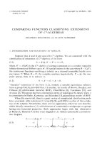
from [2, 22]. The fully packed loop model (FPL model, for short; see for example [1]) is a
model of (not necessarily closed) polygons on a lattice such that each vertex of the lattice
is on exactly one polygon. Whether or not these polygons are closed, we will refer to
them as loops.
Figure 1.1. ThesquaregridQ
7
Throughout this article, we consider this model on the square grid of side length n − 1,
which we denote by Q
n
. See Figure 1.1 for a picture of Q
7
. The polygons consist of
horizontal or vertical edges connecting vertices of Q
n
, and edges that lead outside of
Q
n
from a vertex along the border of Q
n
, see Figure 1.2 for an example of an allowed
configuration in the FPL model. We call the edges that stick outside of Q
n
external
links. The reader is referred to Figure 2.1 for an illustration of the external links of the
square Q
11
. (The labels should be ignored at this point.) It should be noted that the
four corner points are incident to a horizontal and a vertical external link. We shall be
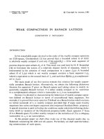
interested here in allowed configurations in the FPL model, in the sequel referred to as
FPL configurations,withperiodic boundary conditions. These are FPL configurations
where, around the border of Q
n
, every other external link of Q
n
is part of a polygon.
The FPL configuration in Figure 1.2 is in fact a configuration with periodic boundary
conditions.
Every FPL configuration defines in a natural way a (non-crossing) matching of the
external links by matching those which are on the same polygon (loop). We are interested
in the number of FPL configurations corresponding to a fixed matching. Thanks to a
theorem of Wieland [21] (see Theorem 2.1), this number is invariant if the matching is
rotated around Q
n
. This allows one to represent a matching in form of a chord diagram
of 2n points placed around a circle, see Figure 1.3 for the chord diagram representation
of the matching corresponding to the FPL configuration in Figure 1.2.
the electronic journal of combinatorics 11(2) (2005), #R16 2
Figure 1.2. An FPL configuration on Q
7
with periodic boundary conditions
Figure 1.3. The chord diagram representation of a matching
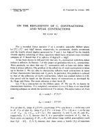
The two conjectures by Zuber which we address in this paper concern FPL configura-
tions corresponding to a matching with m nested arches. More precisely, let X represent
a fixed (non-crossing) matching with n−m arches. By adding m nested arches, we obtain
a certain matching. (See Figure 1.4 for a schematic picture of the matching which is
composed in this way.) The first of Zuber’s conjectures states that the number of FPL
configurations which has this matching as associated matching is polynomial in m.In
fact, the complete statement is even more precise. It makes use of the fact that to any
matching X one can associate a Ferrers diagram λ(X) in a natural way (see Section 2.4
for a detailed explanation).
m
X
Figure 1.4. The matching composed out of a matching X and m nested arches
Conjecture 1.1 ([22, Conj. 6]). Let X be a given non-crossing matching with n − m
arches, and let X ∪ m denote the matching arising from X by adding m nested arches.
Then the number A
X
(m) of FPL configurations which have X∪m as associated matching is
equal to
1
|X|!
P
X
(m), where P
X
(m) is a polynomial of degree |λ(X)| with integer coefficients,
and its highest degree coefficient is equal to dim(λ(X)). Here, |λ(X)| denotes the size
of the Ferrers diagram λ(X), and dim(λ(X)) denotes the dimension of the irreducible
representation of the symmetric group S
|λ(X)|
indexed by the Ferrers diagram λ(X)(which
is given by the hook formula; see (2.1)).
the electronic journal of combinatorics 11(2) (2005), #R16 3
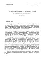
The second conjecture of Zuber generalizes Conjecture 1.1 to the case where a bundle
of nested arches is squeezed between two given matchings. More precisely, let X and Y
be two given (non-crossing) matchings. We produce a new matching by placing X and
Y along our circle that we use for representing matchings, together with m nested arches
which we place in between. (See Figure 1.5 for a schematic picture.) We denote this
matching by X ∪ m ∪ Y .
m
X
Y
Figure 1.5. Squeezing m nested arches between two matchings X and Y
Conjecture 1.2 ([22, Conj. 7]). Let X and Y be two non-crossing matchings. Then the
number A
X,Y
(m) of FPL configurations which have X ∪ m ∪ Y as associated matching is
equal to
1
|λ(X)|! |λ(Y )|!
P
X,Y
(m), where P
X,Y
(m) is a polynomial of degree |λ(X)|+|λ(Y )| with
integer coefficients, and its highest degree coefficient is equal to dim(λ(X)) · dim(λ(Y )).
It is clear that Conjecture 1.2 is a generalization of Conjecture 1.1, since A
X
(m)=
A
X,∅
(m) for any non-crossing matching X,where∅ denotes the empty matching. Never-
theless, we shall treat both conjectures separately, because this will allow us to obtain,
in fact, sharper results than just the statements in the conjectures, with our result cov-
ering Conjecture 1.1 — see Theorem 4.2 and Section 5 — being more precise than the
corresponding result concerning Conjecture 1.2 — see Theorem 6.7. We must stress at
this point that, while we succeed to prove Conjecture 1.1 completely, we are able to prove
Conjecture 1.2 only for “large” m, see the end of Section 6 for the precise statement.
There we also give an explanation of the difficulty of closing the gap.
We conclude the introduction by outlining the proofs of our results, and by explaining
the organisation of our paper at the same time. All notation and prerequisites that we
are going to use in these proofs are summarized in Section 2 below.
Our proofs are based on two observations due to de Gier in [6, Sec. 3] (as are the proofs
in [2, 7, 9]): if one considers the FPL configurations corresponding to a given matching
which has a big number of nested arches, there are many edges which are occupied by
any such FPL configuration. We explain this observation, with focus on our particular
problem, in Section 3. As a consequence, we can split our enumeration problem into the
problem of enumerating configurations in two separate subregions of Q
n
,seetheexpla-
nations accompanying Figure 4.1, respectively Figure 6.2. While one of the regions does
not depend on m, the others grow with m. It remains the task of establishing that the
number of configurations in the latter subregions grows polynomially with m.Inorder
to do so, we use the second observation of de Gier, namely the existence of a bijection
between FPL configurations (subject to certain constraints on the edges) and rhombus
the electronic journal of combinatorics 11(2) (2005), #R16 4
tilings, see the proofs of Theorem 4.2 and Lemma 6.4. In the case of Conjecture 1.1,
the rhombus tilings can be enumerated by an application of the hook-content formula
(recalled in Theorem 2.2), while in the case of Conjecture 1.2 we use a standard cor-
respondence between rhombus tilings and non-intersecting lattice paths, followed by an
application of the Lindstr¨om–Gessel–Viennot theorem (recalled in Lemma 2.3), to obtain
a determinant for the number of rhombus tilings, see the proof of Lemma 6.4. In both
cases, the polynomial nature of the number of rhombus tilings is immediately obvious, if
m is “large enough.” To cover the case of “small” m of Conjecture 1.1 as well, we employ
a somewhat indirect argument, which is based on a variation of the above reasoning, see
Section 5. Finally, for the proof of the more specific assertions in Conjectures 1.1 and 1.2
on the integrality of the coefficients of the polynomials (after renormalization) and on the
leading coefficient, we need several technical lemmas (to be precise, Lemmas 4.1, 6.2 and
6.6). These are implied by Theorem 7.1 (see also Corollary 7.4), which is the subject of
Section 7.
2. Preliminaries
1
2
3
−1
0
−n
2n
2n − 1
−2n +1
−n +1
Figure 2.1. The labelling of the external links
2.1. Notation and conventions concerning FPL configurations. The reader should
recall from the introduction that any FPL configuration defines a matching on the external
links occupied by the polygons, by matching those which are on the same polygon. We
call this matching the matching associated to the FPL configuration. When we think of
the matching as being fixed, and when we consider all FPL configurations having this
matching as associated matching, we shall also speak of these FPL configurations as the
“FPL configurations corresponding to this fixed matching.”
We label the 4n external links around Q
n
by {−2n+1, −2n+2, ,2n−1, 2n} clockwise
starting from the right-most link on the bottom side of the square, see Figure 2.1. If α is
an external link of the square, we denote its label by L(α). Throughout this paper, all the
the electronic journal of combinatorics 11(2) (2005), #R16 5
FPL configurations that are considered are configurations which correspond to matchings
of either the even labelled external links or the odd labelled external links.
2.2. Wieland’s rotational invariance. Let X be a non-crossing matching of the set of
even (odd) labelled external links. Let
˜
X be the “rotated” matching of the odd (even)
external links defined by the property that the links labelled i and j in X are matched if
and only if the links labelled i +1andj + 1 are matched in
˜
X, where we identify 2n +1
and −2n +1. Let FPL(X) denote the set of FPL configurations corresponding to the
matching X. Wieland [21] proved the following surprising result.
Theorem 2.1 (Wieland). For any matching X of the even (odd) labelled external links,
we have
|FPL(X)| = |FPL(
˜
X)|.
In other terms, the number of FPL configurations corresponding to a given matching is
invariant under rotation of the “positioning” of the matching around the square. As we
mentioned already in the introduction, this being the case, we can represent matchings
in terms of chord diagrams of 2n points placed around a circle (see Figure 1.3).
2.3. Partitions and Ferrers diagrams. Next we explain our notation concerning parti-
tions and Ferrers diagrams (see e.g. [20, Ch. 7]). A partition is a vector λ =(λ
1
,λ
2
, ,λ
)
of positive integers such that λ
1
≥ λ
2
≥ ··· ≥ λ
. For convenience, we shall sometimes
use exponential notation. For example, the partition (3, 3, 3, 2, 1, 1) will also be denoted
as (3
3
, 2, 1
2
). To each partition λ, one associates its Ferrers diagram, which is the left-
justified arrangement of cells with λ
i
cells in the i-th row, i =1, 2, ,. See Figure 2.3
for the Ferrers diagram of the partition (7, 5, 2, 2, 1, 1). (At this point, the labels should
be disregarded.) We will usually identify a Ferrers diagram with the corresponding par-
tition; for example we will say “the Ferrers diagram (λ
1
, ,λ
)” to mean “the Ferrers
diagram corresponding to the partition (λ
1
, ,λ
)”. The size |λ| of a Ferrers diagram λ
is given by the total number of cells of λ. The partition conjugate to λ is the partition
λ
=(λ
1
,λ
2
, ,λ
λ
1
), where λ
j
is the length of the j-th column of the Ferrers diagram of
λ.
Given a Ferrers diagram λ, we write (i, j) for the cell in the i-th row and the j-th
column of λ. We use the notation u =(i, j) ∈ λ to express the fact that u is a cell of λ.
Given a cell u,wedenotebyc(u):=j −i the content of u and by h(u):=λ
i
+λ
j
−i−j +1
the hook length of u,whereλ is the partition associated to λ.
It is well-known (see e.g. [11, p. 50]), that the dimension of the irreducible representation
of the symmetric group S
|λ|
indexed by a partition (or, equivalently, by a Ferrers diagram)
λ, which we denote by dim(λ), is given by the hook-length formula due to Frame, Robinson
and Thrall [10],
(2.1) dim(λ)=
n!
u∈λ
h
u
.
the electronic journal of combinatorics 11(2) (2005), #R16 6
2.4. How to associate a Ferrers diagram to a matching. Let X be a non-crossing
matching on the set {1, 2, ,2d}, that is, an involution of this set with no fixed points
which can be represented by non-crossing arches in the upper half-plane (see Figure 2.2
for an example of a non-crossing matching of the set {1, 2, ,16}). Such a non-crossing
matching can be translated into a 0-1-sequence v(X)=v
1
v
2
v
2d
of length 2d by letting
v
i
=0ifX(i) >i,andv
i
=1ifX(i) <i. For example, if X is the matching appearing
in Figure 2.2, then v = 0010010011101101.
1
2
34
5
6
78
9
10
11
12
13
14
15
16
Figure 2.2. A planar matching
1
1
1
11
1
1
1
0
0
0
0
0
0
0
0
Figure 2.3. A Ferrers diagram and its d-code
On the other hand, any 0-1-sequence can be translated into a Ferrers diagram by reading
the 0-1-sequence from left to right and interpreting a 0 as a unit up-step and a 1 as unit
right-step. From the starting point of the obtained path we draw a vertical segment up-
wards, and from the end point a horizontal segment left-wards. By definition, the region
enclosed by the path, the vertical and the horizontal segment is the Ferrers diagram
associated to the given matching. See Figure 2.3 for the Ferrers diagram associated to
the matching in Figure 2.2. (In the figure, for the sake of clarity, we have labelled the
up-steps of the path by 0 and its right-steps by 1.) In the sequel, we shall denote the
Ferrers diagram associated to X by λ(X).
Conversely, given a Ferrers diagram λ, there are several 0-1-sequences which produce
λ by the above described procedure. Namely, by moving along the lower/right boundary
of λ from lower-left to top-right, and recording a 0 for every up-step and a 1 for every
right-step, we obtain one such 0-1-sequence. Prepending an arbitrary number of 0’s and
appending an arbitrary number of 1’s we obtain all the other sequences which give rise
to λ by the above procedure. Out of those, we shall make particular use of the so-called
the electronic journal of combinatorics 11(2) (2005), #R16 7
d-code of λ (see [20, Ex. 7.59]). Here, d is a positive integer such that λ is contained in the
Ferrers diagram (d
d
). We embed λ in (d
d
) so that the diagram λ is located in the top-left
corner of the square (d
d
). We delete the lower side and the right side of the square (d
d
).
(See Figure 2.3 for an example where d =8andλ =(7, 5, 2, 2, 1, 1).) Now, starting from
the lower/left corner of the square, we move, as before, along the lower/right boundary
of the figure from lower-left to top-right, recording a 0 for every up-step and a 1 for every
right-step. By definition, the obtained 0-1-sequence is the d-code of λ. Clearly, the d-code
has exactly d occurrences of 0 and d occurrences of 1. For example, the 8-code of the
Ferrers diagram (7, 5, 2, 2, 1, 1) is 0010010011101101.
2.5. An enumeration result for rhombus tilings. In the proof of Theorem 4.2, we
shall need a general result on the enumeration of rhombus tilings of certain subregions of
the regular triangular lattice in the plane, which are indexed by Ferrers diagrams. (Here,
and in the sequel, by a rhombus tiling we mean a tiling by rhombi of unit side lengths and
angles of 60
◦
and 120
◦
.) This result appeared in an equivalent form in [2, Theorem 2.6]. As
is shown there, it follows from Stanley’s hook-content formula [19, Theorem 15.3], via the
standard bijection between rhombus tilings and non-intersecting lattice paths, followed by
the standard bijection between non-intersecting lattice paths and semistandard tableaux.
Let λ be a Ferrers diagram contained in the square (d
d
), and let h be a non-negative
integer h. WedefinetheregionR(λ, d, h) to be a pentagon with some notches along
the top side. More precisely (see Figure 2.4 where the region R(λ, 8, 3) is shown, with λ
the Ferrers diagram (7, 5, 2, 2, 1, 1) from Figure 2.3), the region R(λ, d, h) is the pentagon
with base side and bottom-left side equal to d,top-leftsideh,atopsideoflength2d
with notches which will be explained in just a moment, and right side equal to d + h.To
determine the notches along the top side, we read the d-code of λ, and we put a notch
whenever we read a 0, while we leave a horizontal piece whenever we read a 1.
d
d
h
d + h
00 00 00 0 011 1 111 11
d-code of λ
Figure 2.4. The region R(λ, d, h)
We can now state the announced enumeration result for rhombus tilings of the regions
R(λ, d, h).
the electronic journal of combinatorics 11(2) (2005), #R16 8
Theorem 2.2. Given a Ferrers diagram λ contained in the square (d
d
) and a positive
integer h, the number of rhombus tilings of the region R(λ, d, h) is given by SSY T(λ, d+h),
where
(2.2) SSY T(λ, N)=
u∈λ
c(u)+N
h(u)
,
with c(u) and h(u) the content and the hook length of u, respectively, as defined in Sec-
tion 2.3.
Figure 2.5. The reduced region
Remark. The choice of the notation SSY T(λ, N) comes from the fact that the number
in (2.2) counts at the same time the number of semistandard tableaux of shape λ with
entries at most N (cf. [19, Theorem 15.3]). Indeed, implicitly in the proof of the above
theorem which we give below is a bijection between the rhombus tilings in the statement
of the theorem and these semistandard tableaux.
Proof of Theorem 2.2. It should be observed that, due to the nature of the region
R(λ, d, h), there are several “forced” subregions, that is, subregions where the tiling is
completely determined. For example, the right-most layer in Figure 2.4 must necessarily
be completely filled with right-oriented rhombi, while the first two upper-left layers must
be filled with horizontally symmetric rhombi. If we remove all the “forced” rhombi, then
a smaller region remains. See Figure 2.5 for the result of this reduction applied to the
region in Figure 2.4. To the obtained region we may apply Theorems 2.6 and 2.5 from
[2]. As a result, we obtain the desired formula.
2.6. The Lindstr¨om–Gessel–Viennot formula. It is well-known that rhombus tilings
are (usually) in bijection with families of non-intersecting lattice paths. We shall make
use of this bijection in Section 6, together with the main result on the enumeration of
non-intersecting lattice paths, which is a determinantal formula due to Lindstr¨om [16].
In the combinatorial literature, it is most often attributed to Gessel and Viennot [12, 13],
but it can actually be traced back to Karlin and McGregor [14, 15].
the electronic journal of combinatorics 11(2) (2005), #R16 9
X
M
Figure 3.1. Placing the matching around Q
n
Let us briefly recall that formula, or, more precisely, a simplified version tailored for
our purposes. We consider lattice paths in the planar integer lattice Z
2
consisting of unit
horizontal and vertical steps in the positive direction. Given two points A and E in Z
2
,
we write P(A → E) for the number of paths starting at A and ending at E.Wesay
that a family of paths is non-intersecting if no two paths in the family have a point in
common.
We can now state the announced main result on non-intersecting lattice paths (see [16,
Lemma 1] or [13, Cor. 2]).
Lemma 2.3. Let A
1
,A
2
, ,A
n
,E
1
,E
2
, ,E
n
be points of the planar integer lattice Z
2
,
such that for all i<jthe point A
i
is (weakly) south-east of the point A
j
, and the point
E
i
is (weakly) south-east of the point E
j
. Then the number of families (P
1
,P
2
, ,P
n
) of
non-intersecting lattice paths, P
i
running from A
i
to E
i
, i =1, 2, ,n, is given by
(2.3) det (P(A
i
→ E
j
))
1≤i,j≤n
.
3. Fixed edges
In this section, we perform the first step in order to prove Conjecture 1.1. Let X be
a given non-crossing matching with d arches. As in the statement of the conjecture, let
X ∪m be the matching obtained by adding m nested arches to X. Thanks to Theorem 2.1
of Wieland, we may place X ∪ m in an arbitrary way around Q
n
= Q
d+m
, without
changing the number of corresponding FPL configurations. We place X ∪ m so that,
using Lemma 3.1 below, the FPL configurations corresponding to the matching will have
as many forced edges as possible.
To be precise, we place X ∪ m so that the arches corresponding to X appear on the
very right of the upper side of Q
n
. That is, we place these arches on the external links
labelled n −4d +2,n−4d +4, ,n−2,n. Equivalently, we choose to place the centre M
the electronic journal of combinatorics 11(2) (2005), #R16 10
of the m nested arches on the external link labelled by −n − 2d + 1. See Figure 3.1 for a
schematic picture, and Figure 3.3 for a more elaborate one (in which the added edges in
the interior of the square grid Q
n
should be ignored at this point). In order to guarantee
that X has place along the upper side of the square grid, we must assume that m ≥ 3d.
The following lemma helps to identify edges which are occupied by each FPL configura-
tion corresponding to a given matching. It is a consequence of an iterated use of a result
of de Gier (see [6, Lemma 8] or [2, Lemmas 2.2 and 2.3]). In the sequel, when we speak of
“fixed edges” we always mean edges that have to be occupied by any FPL configuration
under consideration.
Lemma 3.1. Let α = α
1
,α
2
, ,α
k
= β be a sequence of external links, where L(α
i
)=
a +2i mod 4n, for some fixed a, that is, the external links α
1
,α
2
, ,α
k
comprise every
second external link along the stretch between α and β along the border of Q
n
(clockwise).
Furthermore, we suppose that one of the following conditions holds:
(1) α and β are both on the top side of Q
n
, that is, 1 ≤ L(α) <L(β) ≤ n;
(2) α is on the top side and β is on the right side of Q
n
, that is, 1 ≤ L(α) ≤ n<L(β)
and n − L(α) >L(β) − (n +1);
(3) α is on the left side and β is on the right side of Q
n
, that is, n<L(β) ≤ 2n and
−n<L(α) ≤ 0.
For the FPL configurations for which the external links α
1
,α
2
, ,α
k
belong to different
loops, the region of fixed edges is (essentially) triangular (see Figure 3.2 for illustrations
of the region and the fixed edges in its interior; the “essentially” refers to the fact that
in Cases (2) and (3) parts of the triangle are cut off ). More precisely, if one places the
origin O of the coordinate system one unit to the left of the top-left corner of Q
n
,the
coordinates of the triangle are given in the following way: let A
and B
be the points on
the x-axis with x-coordinates L(α) and L(β), respectively, then the region of fixed edges is
given by the intersection of the square Q
n
and the (rectangular isosceles) triangle having
the segment A
B
as basis.
In Cases (2) and (3), the configurations are completely fixed as “zig-zag” paths in the
corner regions of Q
n
where a part of the triangle was cut off (see again Figure 3.2).More
precisely, in Case (2), this region is the reflexion of the corresponding cut off part of the
triangle in the right side of Q
n
, and in Case (3) it is that region and also the reflexion of
the corresponding cut off part on the left in the left side of Q
n
.
We use this lemma to determine the set of fixed edges of the FPL configurations corre-
sponding to the matching X ∪ m in Conjecture 1.1. For convenience (the reader should
consult Figure 3.3 while reading the following definitions), we let A, B, C, D, E be the bor-
der vertices of the external links labelled n − 4d +3, n − 1, n +2d, −n +2d, −n +4d − 2,
respectively, we let J be the intersection point of the line connecting D and M and the
line emanating diagonally from B,weletK be the intersection point of the latter line
emanating from B and the line emanating diagonally (to the right) from A,andweletL
be the intersection point of the latter line emanating from A and the line connecting C
the electronic journal of combinatorics 11(2) (2005), #R16 11
(3)
(1)
(2)
O
O
O
α
α
α
β
β
β
A
A
A
B
B
B
Figure 3.2. The possible regions of fixed edges determined by a sequence of
external links belonging to distinct loops
the electronic journal of combinatorics 11(2) (2005), #R16 12
M
X
A
B
C
D
E
J
K
L
Figure 3.3. The set of fixed edges
and M . We state the result of the application of Lemma 3.1 to our case in form of the
following lemma.
the electronic journal of combinatorics 11(2) (2005), #R16 13
Lemma 3.2. The region of fixed edges of the FPL configurations corresponding to the
matching in Conjecture 1.1 contains all the edges indicated in Figure 3.3, that is:
(1) all the horizontal edges in the rectangular region JKLM,
(2) every other horizontal edge in the pentagonal region AKJDE as indicated in the
figure,
(3) every other horizontal edge in the region BCLK as indicated in the figure,
(4) the zig-zag lines in the corner regions above the line EA, respectively below the
lines DM and MC, as indicated in the figure.
Proof. This result follows by applying Lemma 3.1 to all the external links corresponding
to the m nested arches which are on the left of the centre M plus the “first” external link
of the matching X, on the one hand, and to all the external links corresponding to the m
nested arches which are on the right of the centre M plus the “last” external link of the
matching X, on the other hand. More precisely, we apply Lemma 3.1 to the sets
{α an external link with − n − 2d +2≤ L(α) ≤ n − 4d +2orL(α) ≥ 3n − 2d}
and
{α an external link with either L(α) ≤−n − 2d or L(α) ≥ n}.
The triangles forming the respective regions of fixed edges are drawn by dashed lines in
Figure 3.3. Note that the two triangles of fixed edges overlap in the rectangular region
JKLM, where the fixed edges form parallel horizontal lines.
4. Proof of Conjecture 1.1 for m large enough
Let X be a non-crossing matching consisting of d arches, and let m be a positive integer
such that m ≥ 3d. As in Conjecture 1.1, we denote the matching arising by adding m
nested arches to X by X ∪ m. The goal of this section is to give an explicit formula
for the number A
X
(m) of FPL configurations corresponding to the matching X ∪ m (cf.
Figure 1.4), which implies Conjecture 1.1 for m ≥ 3d, see Theorem 4.2.
Recall from Section 3 how we place this matching around the grid Q
n
= Q
d+m
,see
Figure 3.3, where we have chosen d =5,m = 23, and, hence, n = d +m = 28. The reader
should furthermore recall the placement of the points A, B, C, D, E, J, K, L, M.Letξ
1
be
the segment which connects the point which is half a unit to the left of A and the point
whichishalfaunitleftofK, see Figure 4.1.
There are exactly 2d − 2 possible vertical edges that cross the segment ξ
1
.Wedenote
them by e
1
,e
2
, ,e
2d−2
, starting from the top one and proceeding south-east. We claim
that among those there are exactly d−1 which are occupied by an FPL configuration. To
see this, we first note that in the rectangular region JKLM there are m − d + 1 parallel
lines strictly below K. Each of them must be part of one of the m + 1 loops starting on
the external links labelled {−n − 2d +2, −n − 2d +4, ,n− 4d, n − 4d +2} (these are
the external links “between” M and A, in clockwise direction). Hence there are exactly d
loops that cross the segment ξ
1
, which implies that any FPL configuration occupies exactly
d − 1 vertical edges out of {e
1
,e
2
, ,e
2d−2
},asweclaimed. Weencodeachoiceofd − 1
the electronic journal of combinatorics 11(2) (2005), #R16 14
X
M
A
B
C
D
E
J
K
L
ξ
1
Figure 4.1. Splitting the problem
edges from {e
1
,e
2
, ,e
2d−2
} by a subset E from {1, 2, ,2d−2}, by making the obvious
identification that the choice of e
i
1
,e
i
2
, ,e
i
d−1
is encoded by E = {i
1
,i
2
, ,i
d−1
}.
On the other hand, any such choice is equivalent to the choice of a Ferrers diagram
contained in the square Ferrers diagram ((d − 1)
d−1
) by the following construction. Let
the electronic journal of combinatorics 11(2) (2005), #R16 15
ξ
1
ξ
2
X
E
Figure 4.2. The numbers a
X
(E)
E⊂{1, 2, ,2d − 2} be of cardinality d − 1. Let c
E
:= c
1
c
2
c
2d−2
be the binary string
defined by c
i
=0ifandonlyifi ∈E. The string c
E
obtained in this way determines a
Ferrers diagram, as we described in Section 2.3. We denote this Ferrers diagram by λ(E).
In the example in Figure 4.1, we have E = {2, 5, 6, 8} and, hence, λ(E)=(4, 3, 3, 1).
It is obvious from the picture, that, once we have chosen the vertical edges along
ξ
1
belonging to an FPL configuration with associated matching X ∪ m (that is, the
vertical edges out of {e
1
,e
2
, ,e
2d−2
} which are occupied by the FPL configuration), the
configuration can be completed separately in the region to the “left” of ξ
1
(that is, in the
region AKJDE) and to the “right” of ξ
1
(that is, in the region ABCLK). In particular, it
is not difficult to see that that the number of FPL configurations with associated matching
X ∪ m which, out of {e
1
,e
2
, ,e
2d−2
}, occupy a fixed subset of vertical edges, is equal
to the number of FPL configurations in the region AKJDE times the number of FPL
configurations in the region ABCLK which respect the matching X.
Clearly, the region ABCLK to the right of ξ
1
does not depend on m. Wedenotethe
number of FPL configurations of that region which respect the matching X and whose
set of edges from {e
1
,e
2
, ,e
2d−2
} is encoded by E by a
X
(E). For example, if X is the
matching {1 ↔ 2, 3 ↔ 4, 5 ↔ 6},andifE is the set {1, 4},thenwehavea
X
(E)=6. The
six configurations corresponding to this choice of X and E are shown in Figure 4.3, where
the arches corresponding to X and the edges corresponding to ξ
1
are marked in bold-face.
the electronic journal of combinatorics 11(2) (2005), #R16 16
Figure 4.3. The six configurations corresponding to X = {1 ↔ 2, 3 ↔ 4, 5 ↔
6} and E = {1, 4}
We have λ(X)=(2, 1) and λ(E)=(1, 1). In particular, λ(E) ⊆ λ(X). The next lemma
shows that this is not an accident.
Lemma 4.1. Let X be a non-crossing matching with d arches and let E beasubsetof
{1, 2, ,2d − 2} consisting of d − 1 elements.
(1) If λ(E) ⊆ λ(X), then a
X
(E)=0.
(2) If λ(E)=λ(X), then a
X
(E)=1.
Proof. This follows from Corollary 7.4.(1) and (3).
Equipped with this lemma, we are now able to prove the first main result of this paper.
Theorem 4.2. Let X be a non-crossing matching with d arches, and let m ≥ 3d. Then
(4.1) A
X
(m)=SSY T(λ(X),m− 2d +1)+
E:λ(E) λ(X)
a
X
(E) · SSY T(λ(E),m− 2d +1).
Proof. Let us fix d − 1 edges from {e
1
,e
2
, ,e
2d−2
}, encoded by the set E.Inviewof
Lemma 4.1, it suffices to show that the number of configurations on the left of the segment
ξ
1
(more precisely, in the region AKJDE; see Figure 4.1) which, out of {e
1
,e
2
, ,e
2d−2
},
occupy exactly the edges encoded by E is equal to SSY T(λ(E),m− 2d +1). Todoso,
we proceed in a way similar to the proof of the main results in [2]. That is, we translate
the problem of enumerating the latter FPL configurations into a problem of enumerating
rhombus tilings.
We say that a vertex is free if it belongs to exactly one fixed edge. We draw a triangle
around any free vertex in the region AKJDE in such a way that two free vertices are
the electronic journal of combinatorics 11(2) (2005), #R16 17
Figure 4.4. Drawing triangles
neighbours if and only if the corresponding triangles share an edge. In the case which is
illustrated in Figure 4.1, this leads to the picture in Figure 4.4.
Now we make a deformation of the obtained set of triangles in such a way that all the
internal angles become 60
◦
. As a result, we obtain the region R(λ(E),d− 1,m− 3d +2)
defined in Section 2.5, see Figure 4.5. As in [2], it is not difficult to see that the FPL
configurations in the region AKJDE are in bijection with the rhombus tilings of the region
R(λ(E),d− 1,m− 3d + 2). Indeed, to go from a rhombus tiling to the corresponding FPL
configuration, for every rhombus in the tiling one connects the free vertices which are in
the interior of the two triangles forming the rhombus by an edge. Hence the result follows
from Theorem 2.2.
the electronic journal of combinatorics 11(2) (2005), #R16 18
Figure 4.5. Getting the regions R(E,m+3d − 2)
Zuber’s Conjecture 1.1, in the case that m ≥ 3d, is now a simple corollary of the above
theorem.
Proof of Conjecture 1.1 for m ≥ 3d. The polynomiality in m of A
X
(m) is obvious from
(4.1) and (2.2). The assertion about the integrality of the coefficients of the “numer-
ator” polynomial P
X
(m) follows from the simple fact that the hook product
u∈λ
h
u
is a divisor of |λ|! for any partition λ. Finally, to see that the leading coefficient of
P
X
(m)isdim(λ(X)), one first observes that the leading term in (4.1) appears in the term
SSY T(λ(X),m−2d+ 1). The claim follows now by a combination of (2.2) and (2.1).
5. Proof of Conjecture 1.1 for small m
To prove Conjecture 1.1 for m<3d, we choose a different placement of the matching
X ∪ m, namely, we place X around the top-right corner of the square Q
n
. To be precise,
we place X ∪ m so that the arches corresponding to X occupy the external links labelled
n − 2d +2,n− 2d +4, ,n+2d, see Figure 5.1 for an example where n = 28, d =7,
and m = 21. (There, the positioning of the matching X is indicated by the black hook.
The edges in the interior of the square grid should be ignored at this point.) In fact, the
figure shows an example where m ≥ 2d, and, strange as it may seem, this is what we shall
assume in the sequel. Only at the very end, we shall get rid of this assumption.
We now apply again Lemma 3.1 to determine the edges which are occupied by each
FPL configuration with associated matching X ∪ m. As a result, there are fixed edges
along zig-zag paths in the upper-left and the lower-right corner of the square grid, while
in a pentagonal region located diagonally from lower-left to upper-right every vertex is
the electronic journal of combinatorics 11(2) (2005), #R16 19
X
ξ
1
ξ
2
Figure 5.1. A different placement of the matching around the grid
on exactly one fixed edge, as indicated in Figure 5.1. (There, the pentagonal region
is indicated by the dashed lines.) More precisely, the pentagonal region decomposes
into two halves: in the upper-left half every other horizontal edge is taken by any FPL
configuration, whereas in the lower-right half it is every other vertical edge which is taken
by any FPL configuration.
Now we are argue similarly to the proof of Theorem 4.2. Along the upper-right border,
we mark the segments ξ
1
(the upper-left half; see Figure 5.1) and ξ
2
(the lower-right
half). Let {e
1
,e
2
, ,e
d−2
} be the set of vertical edges which are crossed by ξ
1
,andlet
{f
1
,f
2
, ,f
d−1
} be the set of vertical edges which are crossed by ξ
2
. In Figure 5.4 these
the electronic journal of combinatorics 11(2) (2005), #R16 20
edges are marked in bold face. (Compare with Figures 4.1 and 4.4.) Since any loop
which enters the triangular region in the upper-right corner of the square grid (that is,
the region to the right of the segments ξ
1
and ξ
2
) must necessarily also leave it again, any
FPL configuration with associated matching X ∪m occupies a subset of {e
1
,e
2
, ,e
d−2
},
encoded by E as before, and a subset of {f
1
,f
2
, ,f
d−1
},encodedbyF, such that
|E| = |F| −1. Once a choice of E and F is made, the number of FPL configurations which
cover exactly the vertical edges encoded by E and F decomposes into the product of the
number of possible configurations in the pentagonal region times the number of possible
configurations in the triangular region in the upper-right corner of the square grid. Let us
denote the former number by N(E, F,m,d), and the latter by c(E, F). Writing, as before,
A
X
(m) for the total number of FPL configurations with associated matching X ∪ m,we
have
(5.1) A
X
(m)=
E,F
c(E, F)N(E, F,m,d),
where the sum is over all possible choices of E⊆{1, 2, ,d− 2} and F⊆{1, 2, ,d− 1}
such that |E| = |F| − 1. In the next lemma, we record the properties of the numbers
N(E, F,m,d) which will allow us to conclude the proof of Conjecture 1.1 for m<3d.
Lemma 5.1. For m ≥ 2d, we have
(1) The number N(E, F,m,d) is a polynomial in m.
(2) As a polynomial in m, m divides N(E, F,m,d) for all E and F, except if E =
{1, 2, ,d− 2} and F = {1, 2, ,d− 1}, in which case N(E, F,m,d)=1.
Proof. Our aim is to find a determinantal expression for N(E, F,m,d). To do so, we
proceed as in the proof of Theorem 4.2, that is, we map the possible configurations in the
pentagonal region bijectively to rhombus tilings of a certain region in the regular triangular
lattice. As in the preceding proof, we draw triangles around free vertices (where “free” has
the same meaning as in that proof) in such a way that two free vertices are neighbours if
and only if the corresponding triangles share an edge. The region in the regular triangular
lattice which we obtain for the pentagonal region of Figure 5.1 is shown in Figure 5.2. It is
a hexagon with bottom side of length d − 1, lower-left side of length d − 1, upper-left side
of length m − d + 2, top side of length d − 2, upper-right side of length d, and lower-right
side of length m − d + 1. However, depending on the choice of E and F, along the top side
and along the upper-right side there are some notches (that is, triangles of unit side length
which are missing, as was the case for the region R(E,m−3d + 1) obtained in the proof of
Theorem 4.2; compare with Figure 4.5). In Figure 5.2, the possible places for notches are
labelled {e
1
,e
2
, ,e
d−2
}, respectively {f
1
,f
2
, ,f
d−1
}. The place labelled f
d
cannot be
the place of a notch, and the number of notches out of {f
1
,f
2
, ,f
d−1
} must be exactly
by 1 larger than the number of notches out of {e
1
,e
2
, ,e
d−2
}. An example of a choice
of notches for d =5,m =7,E = {2} and F = {1, 4} (filled by a rhombus tiling of the
resulting region) is shown on the left in Figure 5.3.
Thus, the number N(E, F,m,d) is equal to the number of rhombus tilings of this
hexagonal region with notches. To get a formula for the number of rhombus tilings, we
the electronic journal of combinatorics 11(2) (2005), #R16 21
e
1
e
2
e
d−2
f
1
f
2
f
d
d − 1
d − 1
d
d − 2
m − d +1
m − d +2
Figure 5.2. The region to be tiled
apply the standard bijection between rhombus tilings and families of non-intersecting
lattice paths (see, e.g., [3, 4]). The bijection is obtained as follows. One places vertices in
each of the mid-points of edges along the bottom-left side of the region, and as well in each
mid-point along the downward edges which form part of a notch on the top of the region,
and along the downward edges along the top-right side of the region. (In Figure 5.3 these
midpoints are marked in boldface.) The vertices of the lower-left edges are subsequently
connected to the vertices on top and top-right by paths, by connecting the mid-points
of opposite downward edges in each rhombus of the tiling, see again Figure 5.3. Clearly,
by construction, the paths are non-intersecting. Subsequently, the paths are slightly
rotated, and deformed so that they become rectangular paths. Thus, one obtains families
of paths with starting points A
i
=(−i, i), i =1, 2, ,d − 1, and with end points a
the electronic journal of combinatorics 11(2) (2005), #R16 22
subset of cardinality d − 1 from the points {E
1
,E
2
, ,E
d−2
}∪{F
1
,F
2
, ,F
d
},where
E
i
=(−d + i, m +1),i =1, ,d− 2, and F
j
=(d − j − 1,m− d + j +1),j =1, 2, ,d.
The point F
d
must be among the end points. The family of paths which results from our
example rhombus tiling is shown on the right of Figure 5.3.
•••••••••
•••••••••
•••••••••
•••••••••
•••••••••
•••••••••
•••••••••
•••••••••
•••••••••
•••••••••
•
•
•
•
••••
•
••
•
•
A
1
A
2
A
3
A
4
F
1
F
2
F
3
F
4
F
5
E
3
E
2
E
1
Figure 5.3. A rhombus tiling of the region with notches, and its corresponding
family of non-intersecting lattice paths
Now we can apply Lemma 2.3 to obtain a determinant for the number of rhombus
tilings. The number of paths from a starting point A
i
to an end point, which forms an
entry in the determinant in (2.3), is equal to
m+1+j−d
j+i−d
if the end point is E
j
,andit
is
m
d−j+i−1
if the end point is F
j
. In both cases, this is a polynomial in m, and thus
claim (1) follows.
To prove claim (2), we observe that m divides the second of the above binomial coef-
ficients,
m
d−j+i−1
,aslongasd − j + i − 1 > 0. However, this will be always the case,
except if i =1andj = d. In particular, if we choose an F
j
with j<das an end point, all
the entries in the column corresponding to F
j
in the determinant (2.3) will be divisible by
m, and, hence, the determinant itself. Thus, the only case where the determinant is not
divisible by m is the one where the set of end points is {E
1
,E
2
, ,E
d−2
,F
d
}. This corre-
sponds to the choice E = {1, 2, ,d− 2} and F = {1, 2, ,d− 1}. In addition, in that
case the determinant in (2.3) is equal to 1 because it is the determinant of a triangular
matrix with 1s on the antidiagonal. This completes the proof of the lemma.
We are now in the position to complete the proof of Conjecture 1.1 for m<3d.We
wish to prove that the polynomial which results from the right-hand side of (5.1) by
substituting the determinantal formula for N(E, F,m,d) obtained in the preceding proof
of Lemma 5.1 gives the number of FPL configurations under consideration for all m ≥ 0.
As we remarked earlier, the arguments so far show only that this is indeed the case for
m ≥ 2d.
the electronic journal of combinatorics 11(2) (2005), #R16 23
X
ξ
1
ξ
2
Figure 5.4. Fixed edges for E = {1, ,d− 2} and F = {1, ,d− 1}
We verify next that this is also the case for m = 0. If we put m = 0 in the right-hand side
of (5.1) (with the afore-mentioned substitution for N(E, F,m,d)), then, by Lemma 5.1,
the only term which survives is the one for E = {1, 2, ,d− 2} and F = {1, 2, ,d− 1}.
In addition, in that case we have N(E, F,m,d)=1. Thus,ifm = 0, the expression in
(5.1) is equal to c(E, F), the number of possible configurations in the triangular region
in the upper-right corner of the square grid. Figure 5.4 shows what happens inside this
triangular region for this choice of E and F: from the external links occupied by the
matching X there propagate zig-zag lines of fixed edges into the interior, so that only a
square region with side length d − 1 remains undetermined. Thus, the number of possible
the electronic journal of combinatorics 11(2) (2005), #R16 24
FPL configurations inside this triangular region is indeed equal to the number of FPL
configurations with associated matching X (that is, FPL configurations on the square Q
d
with associated matching X), which is exactly what we wanted to prove.
While it seems that we have still a large gap (namely the values of m between 1 and
2d − 1) to overcome, the assertion now follows: let H
X
(m) denote the polynomial on the
right-hand side of (5.1). By the above arguments we know that, for an arbitrary non-
negative integer m,thenumberA
X
(m)=A
X∪m
(0) of FPL configurations with associated
matching X ∪ m is equal to H
X∪m
(0). Furthermore, for any non-negative integer s we
have A
X∪m
(s)=A
X
(m + s). By the preceding arguments, if s is sufficiently large, we
have also A
X∪m
(s)=H
X∪m
(s)andA
X
(m + s)=H
X
(m + s). However, it also follows
from the preceding arguments that H
X∪m
(s)andH
X
(m + s)arepolynomialsins.Since
they agree for an infinite number of values of s, they must be identical. In particular,
A
X∪m
(0) = H
X∪m
(0) = H
X
(m). Thus, the number A
X∪m
(0) of FPL configurations with
associated matching X ∪ m is indeed given by the same polynomial for any m.Itmust
necessarily be equal to the polynomial found in Section 4 (see the last paragraph of that
section). Conjecture 1.1 is now completely proved.
6. Proof of Conjecture 1.2 for m large enough
In this section we show how the ideas developed in the proof of Theorem 4.2 can be
extended to prove Conjecture 1.2 for large enough m.
Let X and Y be two non-crossing matchings with d and e arches, respectively. Without
loss of generality, we may suppose that d ≥ e. We choose to place the matching X ∪m∪Y
in Conjecture 1.2 in such a way that, again, the set of arches of X appear on the very right
of the upper side of the grid Q
n
= Q
d+e+m
, see Figure 6.1 for a schematic picture, that
is, we place these arches on the external links labelled n − 4d +2,n− 4d +4, ,n− 2,n.
In order to guarantee that X has place along the upper side of the square grid, we must
assume that m ≥ 3d − e.
Next we determine the set of fixed edges using Lemma 3.1. For convenience (the reader
should consult Figure 6.2 while reading the following definitions; it contains an example
with n = 15, d =3,e =2andm = 10), we let A, B, C, F, G, D, E (in this order!) be
the border vertices of the external links labelled n − 4d +3, n − 1, n +2d +2e − 2,
−n − 2d − 2e +3,−n − 2d +2e − 1, −n +2d − 2e +2,−n +4d − 2, respectively, we let K
be the point in the interior of Q
n
which makes ABK into a rectangular isosceles triangle,
with the right angle at K,weletM be the analogous point which makes FGM into
a rectangular isosceles triangle, with the right angle at M,weletJ be the intersection
point of the line connecting F and M and the line connecting B and K,andweletL be
the intersection point of the line connecting G and M and the line connecting A and K.
We state the result of the application of Lemma 3.1 to the current case in form of the
following lemma.
Lemma 6.1. The region of fixed edges of the FPL configurations corresponding to the
matching X ∪ m ∪ Y contains all the edges indicated in Figure 6.2, that is:
(1) all the horizontal edges in the rectangular region JKLM,
the electronic journal of combinatorics 11(2) (2005), #R16 25