A HEAT TRANSFER TEXTBOOK - THIRD EDITION Episode 3 Part 4 potx
Bạn đang xem bản rút gọn của tài liệu. Xem và tải ngay bản đầy đủ của tài liệu tại đây (248.44 KB, 25 trang )
564 Radiative heat transfer §10.5
even emit additional photons. The result is that fluids can play a role in
the thermal radiation to the the surfaces that surround them.
We have ignored this effect so far because it is generally very small,
especially in air and if the distance between the surfaces is on the or-
der of meters or less. When other gases are involved, especially at high
temperatures, as in furnaces, or when long distances are involved, as in
the atmosphere, gas radiation can become an important part of the heat
exchange process.
How gases interact with photons
The photons of radiant energy passing through a gaseous region can be
impeded in two ways. Some can be “scattered,” or deflected, in various
directions, and some can be absorbed into the molecules. Scattering is
a fairly minor influence in most gases unless they contain foreign par-
ticles, such as dust or fog. In cloudless air, for example, we are aware
of the scattering of sunlight only when it passes through many miles of
the atmosphere. Then the shorter wavelengths of sunlight are scattered
(short wavelengths, as it happens, are far more susceptible to scattering
by gas molecules than longer wavelengths, through a process known as
Rayleigh scattering). That scattered light gives the sky its blue hues.
At sunset, sunlight passes through the atmosphere at a shallow angle
for hundreds of miles. Radiation in the blue wavelengths has all been
scattered out before it can be seen. Thus, we see only the unscattered
red hues, just before dark.
When particles suspended in a gas have diameters near the wave-
length of light, a more complex type of scattering can occur, known as Mie
scattering. Such scattering occurs from the water droplets in clouds (of-
ten making them a brilliant white color). It also occurs in gases that con-
tain soot or in pulverized coal combustion. Mie scattering has a strong
angular variation that changes with wavelength and particle size [10.8].
The absorption or emission of radiation by molecules, rather than
particles, will be our principal focus. The interaction of molecules with
radiation — photons, that is — is governed by quantum mechanics. It’s
helpful at this point to recall a few facts from molecular physics. Each
photon has an energy hc
o
/λ, where h is Planck’s constant, c
o
is the speed
of light, and λ is the wavelength of light. Thus, photons of shorter wave-
lengths have higher energies: ultraviolet photons are more energetic than
visible photons, which are in turn more energetic than infrared photons.
It is not surprising that hotter objects emit more visible photons.
§10.5 Gaseous radiation 565
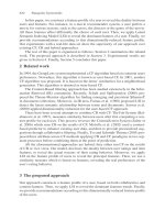
Figure 10.19 Vibrational modes of carbon dioxide and water.
Molecules can store energy by rotation, by vibration (Fig. 10.19), or in
their electrons. Whereas the possible energy of a photon varies smoothly
with wavelength, the energies of molecules are constrained by quantum
mechanics to change only in discrete steps between the molecule’s allow-
able “energy levels.” The available energy levels depend on the molecule’s
chemical structure.
When a molecule emits a photon, its energy drops in a discrete step
from a higher energy level to a lower one. The energy given up is car-
ried away by the photon. As a result, the wavelength of that photon is
determined by the specific change in molecular energy level that caused
it to be emitted. Just the opposite happens when a photon is absorbed:
the photon’s wavelength must match a specific energy level change avail-
able to that particular molecule. As a result, each molecular species can
absorb only photons at, or very close to, particular wavelengths! Often,
these wavelengths are tightly grouped into so-called absorption bands,
outside of which the gas is essentially transparent to photons.
The fact that a molecule’s structure determines how it absorbs and
emits light has been used extensively by chemists as a tool for deducing
566 Radiative heat transfer §10.5
molecular structure. A knowledge of the energy levels in a molecule, in
conjunction with quantum theory, allows specific atoms and bonds to be
identified. This is called spectroscopy (see [10.9, Chpt. 18 & 19] for an
introduction; see [10.10] to go overboard).
At the wavelengths that correspond to thermal radiation at typical
temperatures, it happens that transitions in the vibrational and rotation
modes of molecules have the greatest influence on radiative absorptance.
Such transitions can be driven by photons only when the molecule has
some asymmetry.
4
Thus, for all practical purposes, monatomic and sym-
metrical diatomic molecules are transparent to thermal radiation. The
major components of air—N
2
and O
2
—are therefore nonabsorbing; so,
too, are H
2
and such monatomic gases as argon.
Asymmetrical molecules like CO
2
,H
2
O, CH
4
,O
3
,NH
3
,N
2
O, and SO
2
,
on the other hand, each absorb thermal radiation of certain wavelengths.
The first two of these, CO
2
and H
2
O, are always present in air. To under-
stand how the interaction works, consider the possible vibrations of CO
2
and H
2
O shown in Fig. 10.19. For CO
2
, the topmost mode of vibration
is symmetrical and has no interaction with thermal radiation at normal
pressures. The other three modes produce asymmetries in the molecule
when they occur; each is important to thermal radiation.
The primary absorption wavelength for the two middle modes of CO
2
is 15 µm, which lies in the thermal infrared. The wavelength for the bot-
tommost mode is 4.3 µm. For H
2
O, middle mode of vibration interacts
strongly with thermal radiation at 6.3 µm. The other two both affect
2.7 µm radiation, although the bottom one does so more strongly. In ad-
dition, H
2
O has a rotational mode that absorbs thermal radiation having
wavelengths of 14 µm or more. Both of these molecules show additional
absorption lines at shorter wavelengths, which result from the superpo-
sition of two or more vibrations and their harmonics (e.g., at 2.7 µm for
CO
2
and at 1.9 and 1.4 µm for H
2
O). Additional absorption bands can
appear at high temperature or high pressure.
Absorptance, transmittance, and emittance
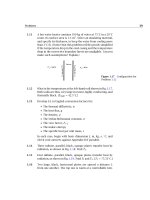
Figure 10.20 shows radiant energy passing through an absorbing gas with
a monochromatic intensity i
λ
. As it passes through an element of thick-
4
The asymmetry required is in the distribution of electric charge — the dipole mo-
ment. A vibration of the molecule must create a fluctuating dipole moment in order
to interact with photons. A rotation interacts with photons only if the molecule has a
permanent dipole moment.
§10.5 Gaseous radiation 567
Figure 10.20 The attenuation of
radiation through an absorbing (and/or
scattering) gas.
ness dx, the intensity will be reduced by an amount di
λ
:
di
λ
=−ρκ
λ
i
λ
dx (10.43)
where ρ is the gas density and κ
λ
is called the monochromatic absorp-
tion coefficient. If the gas scatters radiation, we replace κ
λ
with γ
λ
, the
monochromatic scattering coefficient. If it both absorbs and scatters ra-
diation, we replace κ
λ
with β
λ
≡ κ
λ
+ γ
λ
, the monochromatic extinction
coefficient.
5
The dimensions of κ
λ
, β
λ
, and γ
λ
are all m
2
/kg.
If ρκ
λ
is constant through the gas, eqn. (10.43) can be integrated from
an initial intensity i
λ
0
at x = 0 to obtain
i
λ
(x) = i
λ
0
e
−ρκ
λ
x
(10.44)
This result is called Beer’s law (pronounced “Bayr’s” law). For a gas layer
of a given depth x = L, the ratio of final to initial intensity defines that
layer’s monochromatic transmittance, τ
λ
:
τ
λ
≡
i
λ
(L)
i
λ
0
= e
−ρκ
λ
L
(10.45)
Further, since gases do not reflect radiant energy, τ
λ
+α
λ
= 1. Thus, the
monochromatic absorptance, α
λ
,is
α
λ
= 1 − e
−ρκ
λ
L
(10.46)
Both τ
λ
and α
λ
depend on the density and thickness of the gas layer.
The product ρκ
λ
L is sometimes called the optical depth of the gas. For
very small values of ρκ
λ
L, the gas is transparent to the wavelength λ.
5
All three coefficients, κ
λ
, γ
λ
, and β
λ
, are expressed on a mass basis. They could,
alternatively, have been expressed on a volumetric basis.
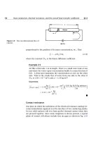
568 Radiative heat transfer §10.5
Figure 10.21 The monochromatic absorptance of a 1.09 m
thick layer of steam at 127
◦
C.
The dependence of α
λ
on λ is normally very strong. As we have seen,
a given molecule will absorb radiation in certain wavelength bands, while
allowing radiation with somewhat higher or lower wavelengths to pass
almost unhindered. Figure 10.21 shows the absorptance of water vapor
as a function of wavelength for a fixed depth. We can see the absorption
bands at wavelengths of 6.3, 2.7, 1.9, and 1.4 µm that were mentioned
before.
A comparison of Fig. 10.21 with Fig. 10.2 readily shows why radia-
tion from the sun, as viewed from the earth’s surface, shows a number
of spikey indentations at certain wavelengths. Several of those indenta-
tions occur in bands where atmospheric water vapor absorbs incoming
solar radiation, in accordance with Fig. 10.21. The other indentations in
Fig. 10.2 occur where ozone and CO
2
absorb radiation. The sun itself
does not have these regions of low emittance; it is just that much of the
radiation in these bands is absorbed by gases in the atmosphere before
it can reach the ground.
Just as α
λ
and ε
λ
are equal to one another for a diffuse solid surface,
they are equal for a gas. We may demonstrate this by considering an
isothermal gas that is in thermal equilibrium with a black enclosure that
contains it. The radiant intensity within the enclosure is that of a black
body, i
λ
b
, at the temperature of the gas and enclosure. Equation (10.43)
shows that a small section of gas absorbs radiation, reducing the inten-
sity by an amount ρκ
λ
i
λ
b
dx. To maintain equilibrium, the gas must
therefore emit an equal amount of radiation:
di
λ
= ρκ
λ
i
λ
b
dx (10.47)
Now, if radiation from some other source is transmitted through
a nonscattering isothermal gas, we can combine the absorption from
§10.5 Gaseous radiation 569
eqn. (10.43) with the emission from eqn. (10.47) to form an energy bal-
ance called the equation of transfer
di
λ
dx
=−ρκ
λ
i
λ
+ρκ
λ
i
λ
b
(10.48)
Integration of this equation yields a result similar to eqn. (10.44):
i
λ
(L) = i
λ
0
e
−ρκ
λ
L
=τ
λ
+i
λ
b
1 − e
−ρκ
λ
L
≡ε
λ
(10.49)
The first righthand term represents the transmission of the incoming
intensity, as in eqn. (10.44), and the second is the radiation emitted by
the gas itself. The coefficient of the second righthand term defines the
monochromatic emittance, ε
λ
, of the gas layer. Finally, comparison to
eqn. (10.46) shows that
ε
λ
= α
λ
= 1 − e
−ρκ
λ
L
(10.50)
Again, we see that for very small ρκ
λ
L the gas will neither absorb nor
emit radiation of wavelength λ.
Heat transfer from gases to walls
We now see that predicting the total emissivity, ε
g
, of a gas layer will be
complex. We have to take account of the gases’ absorption bands as well
as the layer’s thickness and density. Such predictions can be done [10.11],
but they are laborious. For making simpler (but less accurate) estimates,
correlations of ε
g
have been developed.
Such correlations are based on the following model: An isothermal
gas of temperature T
g
and thickness L, is bounded by walls at the single
temperature T
w
. The gas consists of a small fraction of an absorbing
species (say CO
2
) mixed into a nonabsorbing species (say N
2
). If the ab-
sorbing gas has a partial pressure p
a
and the mixture has a total pressure
p, the correlation takes this form:
ε
g
= fn
p
a
L, p, T
g
(10.51)
The parameter p
a
L is a measure of the layer’s optical depth; p and T
g
account for changes in the absorption bands with pressure and temper-
ature.
570 Radiative heat transfer §10.5
Hottel and Sarofim [10.12] provide such correlations for CO
2
and H
2
O,
built from research by Hottel and others before 1960. The correlations
take the form
ε
g
p
a
L, p, T
g
= f
1
p
a
L, T
g
×f
2
p,p
a
,p
a
L
(10.52)
where the experimental functions f
1
and f
2
are plotted in Figs. 10.22 and
10.23 for CO
2
and H
2
O, respectively. The first function, f
1
, is a correla-
tion for a total pressure of p = 1 atm with a very small partial pressure
of the absorbing species. The second function, f
2
, is a correction factor
to account for other values of p
a
or p. Additional corrections must be
applied if both CO
2
and H
2
O are present in the same mixture.
To find the net heat transfer between the gas and the walls, we must
also find the total absorptance, α
g
, of the gas. Despite the equality of the
monochromatic emittance and absorptance, ε
λ
and α
λ
, the total values,
ε
g
and α
g
, will not generally be equal. This is because the absorbed
radiation may come from, say, a wall having a much different temperature
than the gas with a correspondingly different wavelength distribution.
Hottel and Sarofim show that α
g
may be estimated from the correlation
for ε
g
as follows:
6
α
g
=
T
g
T
w
1/2
·ε
p
a
L
T
w
T
g
,p,T
w
(10.53)
Finally, we need to determine an appropriate value of L for a given
enclosure. The correlations just given for ε
g
and α
g
assume L to be
a one-dimensional path through the gas. Even for a pair of flat plates
a distance L apart, this won’t be appropriate since radiation can travel
much farther if it follows a path that is not perpendicular to the plates.
For enclosures that have black walls at a uniform temperature, we can
use an effective path length, L
0
, called the geometrical mean beam length,
to represent both the size and the configuration of a gaseous region. The
geometrical mean beam length is defined as
L
0
≡
4 (volume of gas)
boundary area that is irradiated
(10.54)
Thus, for two infinite parallel plates a distance apart, L
0
= 4A/2A =
2. Some other values of L
0
for gas volumes exchanging heat with all
points on their boundaries are as follow:
6
Hottel originally recommended replacing the exponent 1/2 by 0.65 for CO
2
and
0.45 for H
2
O. Theory, and more recent work, both suggest using the value 1/2 [10.13].
Figure 10.22 Functions used to predict ε
g
= f
1
f
2
for water
vapor in air.
571
Figure 10.23 Functions used to predict ε
g
= f
1
f
2
for CO
2
in
air. All pressures in atmospheres.
572
§10.5 Gaseous radiation 573
• For a sphere of diameter D, L
0
= 2D/3
• For an infinite cylinder of diameter D, L
0
= D
• For a cube of side L, L
0
= 2L/3
• For a cylinder with height = D, L
0
= 2D/3
For cases where the gas is strongly absorbing, better accuracy can be
obtained by replacing the constant 4 in eqn. (10.54) by 3.5, lowering the
mean beam length about 12%.
We are now in position to treat a problem in which hot gases (say
the products of combustion) radiate to a black container. Consider an
example:
Example 10.11
A long cylindrical combustor 40 cm in diameter contains a gas at
1200
◦
C consisting of 0.8 atm N
2
and 0.2 atm CO
2
. What is the net
heat radiated to the walls if they are at 300
◦
C?
Solution. Let us first obtain ε
g
. We have L
0
= D = 0.40 m, a total
pressure of 1.0 atm, p
CO
2
= 0.2 atm, and T = 1200
◦
C = 2651
◦
R.
Then Fig. 10.23a gives f
1
as 0.098 and Fig. 10.23b gives f
2
1, so
ε
g
= 0.098. Next, we use eqn. (10.53) to obtain α
g
, with T
w
= 1031
◦
R,
p
H
2
O
LT
w
/T
g
= 0.031:
α
g
=
1200 + 273
300 + 273
0.5
(0.074) = 0.12
Now we can calculate Q
net
g-w
. For these problems with one wall
surrounding one gas, the use of the mean beam length in finding
ε
g
and α
g
accounts for all geometrical effects, and no view factor is
required. The net heat transfer is calculated using the surface area of
the wall:
Q
net
g-w
= A
w
ε
g
σT
4
g
−α
g
σT
4
w
= π(0.4)(5.67 × 10
−8
)
(0.098)(1473)
4
−(0.12)(573)
4
= 32 kW/m
Total emissivity charts and the mean beam length provide a simple,
but crude, tool for dealing with gas radiation. Since the introduction
574 Radiative heat transfer §10.6
of these ideas in the mid-twentieth century, major advances have been
made in our knowledge of the radiative properties of gases and in the
tools available for solving gas radiation problems. In particular, band
models of gas radiation, and better measurements, have led to better
procedures for dealing with the total radiative properties of gases (see,
in particular, References [10.11] and [10.13]). Tools for dealing with ra-
diation in complex enclosures have also improved. The most versitile
of these is the previously-mentioned Monte Carlo method [10.4, 10.7],
which can deal with nongray, nondiffuse, and nonisothermal walls with
nongray, scattering, and nonisothermal gases. An extensive literature
also deals with approximate analytical techniques, many of which are
based on the idea of a “gray gas” — one for which ε
λ
and α
λ
are inde-
pendent of wavelength. However, as we have pointed out, the gray gas
model is not even a qualitative approximation to the properties of real
gases.
7
Finally, it is worth noting that gaseous radiation is frequently less
important than one might imagine. Consider, for example, two flames: a
bright orange candle flame and a “cold-blue” hydrogen flame. Both have
a great deal of water vapor in them, as a result of oxidizing H
2
. But the
candle will warm your hands if you place them near it and the hydrogen
flame will not. Yet the temperature in the hydrogen flame is higher.It
turns out that what is radiating both heat and light from the candle is soot
— small solid particles of almost thermally black carbon. The CO
2
and
H
2
O in the candle flame actually contribute relatively little to radiation.
10.6 Solar energy
The sun
The sun continually irradiates the earth at a rate of about 1.74×10
14
kW.
If we imagine this energy to be distributed over a circular disk with the
earth’s diameter, the solar irradiation is about 1367 W/m
2
, as measured
by satellites above the atmosphere. Much of this energy reaches the
ground, where it sustains the processes of life.
7
Edwards [10.11] describes the gray gas as a “myth.” He notes, however, that spectral
variations may be overlooked for a gas containing spray droplets or particles [in a
range of sizes] or for some gases that have wide, weak absorption bands within the
spectral range of interest [10.3]. Some accommodation of molecular properties can be
achieved using the weighted sum of gray gases concept [10.12], which treats a real gas
as superposition of gray gases having different properties.
§10.6 Solar energy 575
The temperature of the sun varies from tens of millions of kelvin in its
core to between 4000 and 6000 K at its surface, where most of the sun’s
thermal radiation originates. The wavelength distribution of the sun’s
energy is not quite that of a black body, but it may be approximated as
such. A straightforward calculation (see Problem 10.49) shows that a
black body of the sun’s size and distance from the earth would produce
the same irradiation as the sun if its temperature were 5777 K.
The solar radiation reaching the earth’s surface is always less than
that above the atmosphere owing to atmospheric absorption and the
earth’s curvature and rotation. Solar radiation usually arrives at an angle
of less than 90
◦
to the surface because the sun is rarely directly overhead.
We have seen that a radiant heat flux arriving at an angle less than 90
◦
is reduced by the cosine of that angle (Fig. 10.4). The sun’s angle varies
with latitude, time of day, and day of year. Trigonometry and data for
the earth’s rotation can be used to find the appropriate angle.
Figure 10.2 shows the reduction of solar radiation by atmospheric ab-
sorption for one particular set of atmospheric conditions. In fact, when
the sun passes through the atmosphere at a low angle (near the hori-
zon), the path of radiation through the atmosphere is longer, providing
relatively more opportunity for atmospheric absorption and scattering.
Additional moisture in the air can increase the absorption by H
2
O, and,
of course, clouds can dramatically reduce the solar radiation reaching
the ground. The consequence of these various effects is that the solar
radiation received on the ground is almost never more than 1200 W/m
2
and is often only a few hundred W/m
2
. Extensive data are available for
estimating the ground level solar irradiation at a given location, time, and
date [10.14, 10.15].
The distribution of the Sun’s energy and atmospheric
irradiation
Figure 10.24 shows what becomes of the solar energy that impinges on
the earth if we average it over the year and the globe, taking account of
all kinds of weather. Only 45% of the sun’s energy actually reaches the
earth’s surface. The mean energy received is about 235 W/m
2
if averaged
over the surface and the year. The lower left-hand portion of the figure
shows how this energy is, in turn, all returned to the atmosphere and to
space.
The solar radiation reaching the earth’s surface includes direct radi-
ation that has passed through the atmosphere and diffuse radiation that
576 Radiative heat transfer §10.6
45% reaches
the earth’s
surface
45% is
transmitted
to the earth
directly and
by diffuse
radiation
33% is
reflected
back to
space
22% is absorbed
in the
atmosphere
Sensible heat
transfer to
atmosphere
Evaporation
Net
radiation
from
surface
Radiation that reaches the outer
atmosphere from the sun
The flow of energy from
the earth's surface back to -
and through - the earth's
atmosphere
Figure 10.24 The approximate distribution of the flow of the
sun’s energy to and from the earth’s surface [10.16].
has been scattered, but not absorbed, by the atmosphere. Atmospheric
gases also irradiate the surface. This irradiation is quite important to the
maintaining the temperature of objects on the surface.
In Section 10.5, saw that the energy radiated by a gas depends upon
the depth of the gas, its temperature, and the molecules present in it.
The emissivity of the atmosphere has been characterized in detail [10.16,
10.17, 10.18]. For practical calculations, however, it is often convenient
§10.6 Solar energy 577
to treat the sky as a black radiator having some appropriate temperature.
This effective sky temperature is usually between 5 and 30
◦
C lower that
the ground level air temperature. The sky temperature decreases as the
amount of water vapor in the air goes down. For cloudless skies, the sky
temperature may be estimated using the dew-point temperature, T
dp
, and
the hour past midnight, t:
T
sky
= T
air
0.711 + 0.0056 T
dp
+7.3 × 10
−5
T
2
dp
+0.013 cos(2πt/24)
1/4
(10.55)
where T
sky
and T
air
are in kelvin and T
dp
is in
◦
C. This equation applies
for dew points from −20
◦
Cto30
◦
C[10.19].
It is fortunate that sky temperatures are relatively warm. In the ab-
sence of an atmosphere, we would exchange radiation directly with the
bitter cold of outer space. Our planet would be uninhabitably cold.
Selective emitters, absorbers, and transmitters
We have noted that most of the sun’s energy lies at wavelengths near
the visible region of the electromagnetic spectrum and that most of the
radiation from objects at temperatures typical of the earth’s surface is
on much longer, infrared wavelengths (see pg. 535). One result is that
materials may be chosen or designed to be selectively good emitters or
reflectors of both solar and infrared radiation.
Table 10.4 shows the infrared emittance and solar absorptance for
several materials. Among these, we identify several particularly selective
solar absorbers and solar reflectors. The selective absorbers have a high
absorptance for solar radiation and a low emittance for infrared radia-
tion. Consequently, they do not strongly reradiate the solar energy that
they absorb. The selective solar reflectors, on the other hand, reflect so-
lar energy strongly and also radiate heat efficiently in the infrared. Solar
reflectors stay much cooler than solar absorbers in bright sunlight.
Example 10.12
In Section 10.2, we discussed white paint on a roof as a selective
solar absorber. Consider now a barn roof under a sunlit sky. The
solar radiation on the plane of the roof is 600 W/m
2
, the air temper-
ature is 35
◦
C, and a light breeze produces a convective heat transfer
coefficient of
h = 8 W/m
2
K. The sky temperature is 18
◦
C. Find the
578 Radiative heat transfer §10.6
Table 10.4 Solar absorptance and infrared emittance for sev-
eral surfaces near 300 K [10.4, 10.15].
Surface α
solar
ε
IR
Aluminum, pure 0.09 0.1
Carbon black in acrylic binder 0.94 0.83
Copper, polished 0.30.04
Selective Solar absorbers
Black Cr on Ni plate 0.95 0.09
CuO on Cu (Ebanol C) 0.90 0.16
Nickel black on steel 0.81 0.17
Sputtered cermet on steel 0.96 0.16
Selective Solar Reflectors
Magnesium oxide 0.14 0.7
Snow 0.2–0.35 0.82
White paint
Acrylic 0.26 0.90
Zinc Oxide 0.12–0.18 0.93
temperature of the roof if it is painted with either white acrylic paint
or a non-selective black paint having ε = 0.9.
Solution. Heat loss from the roof to the inside of the barn will lower
the roof temperature. Since we don’t have enough information to eval-
uate that loss, we can make an upper bound on the roof temperature
by assuming that no heat is transferred to the interior. Then, an en-
ergy balance on the roof must account for radiation absorbed from
the sun and the sky and for heat lost by convection and reradiation:
α
solar
q
solar
+ε
IR
σT
4
sky
= h
(
T
roof
−T
air
)
+ε
IR
σT
4
roof
Rearranging and substituting the given numbers,
8
[
T
roof
−(273 + 35)
]
+ε
IR
(5.67 × 10
−8
)
T
4
roof
−(273 + 18)
4
= α
solar
(600)
For the non-selective black paint, α
solar
= ε
IR
= 0.90. Solving by
§10.6 Solar energy 579
iteration, we find
T
roof
= 338 K = 65
◦
C
For white acrylic paint, from Table 10.4, α
solar
= 0.26 and ε
IR
= 0.90.
We find
T
roof
= 312 K = 39
◦
C
The white painted roof is only a few degrees warmer than the air.
Ordinary window glass is a very selective transmitter of solar radia-
tion. Glass is nearly transparent to wavelengths below 2.7 µm or so, pass-
ing more than 90% of the incident solar energy. At longer wavelengths,
in the infrared, glass is virtually opaque to radiation. A consequence of
this fact is that solar energy passing through a window cannot pass back
out as infrared reradiation. This is precisely why we make greenhouses
out of glass. A greenhouse is a structure in which we use glass trap solar
energy in a lower temperature space.
The atmospheric greenhouse effect and global warming
The atmosphere creates a greenhouse effect on the earth’s surface that
is very similar to that caused by a pane of glass. Solar energy passes
through the atmosphere, arriving mainly on wavelengths between about
0.3 and 3 µm. The earth’s surface, having a mean temperature of 15
◦
C
or so, radiates mainly on infrared wavelengths longer than 5 µm. Certain
atmospheric gases have strong absorption bands at these longer wave-
lengths. Those gases absorb energy radiated from the surface, and then
reemit it toward both the surface and outer space. The result is that the
surface remains some 30 K warmer than the atmosphere. In effect, the
atmosphere functions as a radiation shield against infrared heat loss to
space.
The gases mainly responsible for the the atmospheric greenhouse ef-
fect are CO
2
,H
2
O, CH
4
,N
2
O, O
3
, and some chlorofluorcarbons [10.20]. If
the concentration of these gases rises or falls, the strength of the green-
house effect will change and the surface temperature will also rise or fall.
With the exception of the chlorofluorocarbons, each of these gases is cre-
ated, in part, by natural processes: H
2
O by evaporation, CO
2
by animal
respiration, CH
4
through plant decay and digestion by livestock, and so
on. Human activities, however, have significantly increased the concen-
trations of all of the gases. Fossil fuel combustion increased the CO
2
580 Radiative heat transfer §10.6
1880 1900 1920 1940 1960 1980 2000
-0.6
-0.4
-0.2
0.0
0.2
0.4
0.6
0.8
Annual mean
5-year mean
Year
Temperature Anomaly,
˚
C
Figure 10.25 Global surface temperature change relative to
the mean temperature from 1950–1980 (Courtesy of the NASA
Goddard Institute for Space Studies [10.21]).
concentration by more than 30% during the twentieth century. Methane
concentrations have risen through the transportation and leakage of hy-
drocarbon fuels. Ground level ozone concentrations have risen as a result
of photochemical interactions of other pollutants. Chlorofluorocarbons
are human-made chemicals.
In parallel to the rising concentrations of these gases, the surface
temperature of the earth has risen significantly. Over the course of the
twentieth century, a rise of 0.6–0.7 K occurred, with 0.4–0.5 K of that
rise coming after 1950 (see Fig. 10.25). The data showing this rise are
extensive, are derived from multiple sources, and have been the subject
of detailed scrutiny: there is relatively little doubt that surface temper-
atures have increased [10.21, 10.22]. The question of how much of the
rise should be attributed to anthropogenic greenhouse gases, however,
was a subject of intense debate throughout the 1990’s.
Many factors must be considered in examining the causes of global
warming. Carbon dioxide, for example, is present in such high concentra-
tions that adding more of it increases absorption less rapidly than might
be expected. Other gases that are present in smaller concentrations, such
as methane, have far stronger effects per additional kilogram. The con-
§10.6 Solar energy 581
centration of water vapor in the atmosphere rises with increasing surface
temperature, amplifying any warming trend. Increased cloud cover has
both warming and cooling effects. The melting of polar ice caps as tem-
peratures rise reduces the planet’s reflectivity, or albedo, allowing more
solar energy to be absorbed. Small temperature rises that have been
observed in the oceans store enormous amounts of energy that must
accounted. Atmospheric aerosols (two-thirds of which are produced by
sulfate and carbon pollution from fossil fuels) also tend to reduce the
greenhouse effect. All of these factors must be built into an accurate
climate model (see, for example, [10.23]).
The current consensus among mainstream researchers is that the
global warming seen during the last half of the twentieth century is
mainly attributable to human activity, principally through the combus-
tion of fossil fuels [10.22]. Numerical models have been used to project
a continuing temperature rise in the twenty-first century, subject to var-
ious assumptions about the use of fossil fuels and government policies
for reducing greenhouse gas emissions. Regrettably, the outlook is not
very positive, with predictions of twenty-first century warming ranging
from 1.4–5.8 K.
The potential for solar power
One alternative to the continuing use of fossil fuels is solar energy. With
so much solar energy falling upon all parts of the world, and with the
apparent safety, reliability, and cleanliness of most schemes for utiliz-
ing solar energy, one might ask why we do not generally use solar power
already. The reason is that solar power involves many serious heat trans-
fer and thermodynamics design problems and may pose environmental
threats of its own. We shall discuss the problems qualitatively and refer
the reader to [10.15], [10.24], or [10.25] for detailed discussions of the
design of solar energy systems.
Solar energy reaches the earth with very low intensity. We began this
discussion in Chapter 1 by noting that human beings can interface with
only a few hundred watts of energy. We could not live on earth if the sun
were not relatively gentle. It follows that any large solar power source
must concentrate the energy that falls on a huge area. By way of illus-
tration, suppose that we sought to photovoltaically convert 615 W/m
2
of solar energy into electric power with a 15% efficiency (which is not
pessimistic) during 8 hr of each day. This would correspond to a daily
average of 31 W/m
2
, and we would need almost 26 square kilometers (10
square miles) of collector area to match the steady output of an 800 MW
power plant.
582 Radiative heat transfer §10.6
Other forms of solar energy conversion require similarly large areas.
Hydroelectric power — the result of evaporation under the sun’s warming
influence — requires a large reservoir, and watershed, behind the dam.
The burning of organic matter, as wood or grain-based ethanol, requires
a large cornfield or forest to be fed by the sun, and so forth. Any energy
supply that is served by the sun must draw from a large area of the
earth’s surface. Thus, they introduce their own kinds of environmental
complications.
A second problem stems from the intermittent nature of solar devices.
To provide steady power—day and night, rain or shine—requires thermal
storage systems, which add both complication and cost.
These problems are minimal when one uses solar energy merely to
heat air or water to moderate temperatures (50 to 90
◦
C). In this case the
efficiency will improve from just a few percent to as high as 70%. Such
heating can be used for industrial processes (crop drying, for example),
or it can be used on a small scale for domestic heating of air or water.
Figure 10.26 shows a typical configuration of a domestic solar collec-
tor of the flat-plate type. Solar radiation passes through one or more glass
plates and impinges on a plate that absorbs the solar wavelengths. The
absorber plate would be a selective solar absorber, perhaps blackened
copper or nickel. The glass plates might be treated with anti-reflective
coatings, raising their solar transmissivity to 98% or more. Once the en-
ergy is absorbed, it is reemitted as long-wavelength infrared radiation.
Glass is almost opaque in this range, and energy is retained in the collec-
tor by a greenhouse effect. Multiple layers of glass serve to reduce both
reradiative and convective losses from the absorber plate.
Water flowing through tubes, which may be brazed to the absorber
plate, carries the energy away for use. The flow rate is adjusted to give
an appropriate temperature rise.
If the working fluid is to be brought to a fairly high temperature, the
direct radiation from the sun must be focused from a large area down to
a very small region, using reflecting mirrors. Collectors equipped with a
small parabolic reflector, focused on a water or air pipe, can raise the fluid
to between 100 and 200
◦
C. In any scheme intended to produce electrical
power with a conventional thermal cycle, energy must be focused in an
area ratio on the order of 1000 : 1 to achieve a practical cycle efficiency.
It is instructive to compare our energy consumption to the renewable
energy that the earth receives from the sun. Of the 1.74×10
14
kW arriv-
ing from the sun, 33% is simply reflected back into outer space. If we
§10.6 Solar energy 583
Figure 10.26 A typical flat-plate solar collector.
were able to collect and use the remainder, 1.16×10
14
kW, before it too
was reradiated to space, each of the 6 billion or so people on the planet
could expect to use 19 kW. (This figure, of course, ignores all other forms
of life.) In the USA, total energy consumption in 2002 averages roughly
3.2 × 10
9
kW, and, dividing this value into a population of 280 million
people, one finds a per capita consumption of more than 11 kW. While
this is still below the 19 kW “renewable limit”, it should be noted that
only a tiny fraction of this energy comes from renewable sources and
that technology does not currently exist that would allow even a major
fraction of the renewable limit to be collected without massive environ-
mental damage.
There is little doubt that our short-term needs—during the next cen-
tury or so—can be met by our fossil fuel reserves. The continued use
of those fossil fuels is widely expected to amplify the well-documented
trend of global warming. Our long-term hope for an adequate energy
supply may be partially met using solar power. Nuclear fission remains
a promising option, if the difficult problems posed by nuclear waste can
be met. Nuclear fusion—the process by which we might manage to cre-
584 Chapter 10: Radiative heat transfer
ate mini-suns upon the earth—may also be a hope for the future. Under
almost any scenario, however, we will surely be forced to limit the con-
tinuing growth in our energy consumption.
Problems
10.1 What will ε
λ
of the sun appear to be to an observer on the
earth’s surface at λ = 0.2 µm and 0.65 µm? How do these
emittances compare with the real emittances of the sun? [At
0.65 µm, ε
λ
0.77.]
10.2 Plot e
λ
b
against λ for T = 300 K and 10, 000 K with the help
of eqn. (1.30). About what fraction of energy from each black
body is visible?
10.3 A 0.6 mm diameter wire is drawn out through a mandril at
950
◦
C. Its emittance is 0.85. It then passes through a long
cylindrical shield of commercial aluminum sheet, 7 cm in di-
ameter. The shield is horizontal in still air at 25
◦
C. What is the
temperature of the shield? Is it reasonable to neglect natural
convection inside and radiation outside? [T
shield
= 153
◦
C.]
10.4 A1ft
2
shallow pan with adiabatic sides is filled to the brim with
water at 32
◦
F. It radiates to a night sky whose temperature is
360
◦
R, while a 50
◦
F breeze blows over it at 1.5ft/s. Will the
water freeze or warm up?
10.5 A thermometer is held vertically in a room with air at 10
◦
C and
walls at 27
◦
C. What temperature will the thermometer read if
everything can be considered black? State your assumptions.
10.6 Rework Problem 10.5, taking the room to be wall-papered and
considering the thermometer to be nonblack.
10.7 Two thin aluminum plates, the first polished and the second
painted black, are placed horizontally outdoors, where they are
cooled by air at 10
◦
C. The heat transfer coefficient is 5 W/m
2
K
on both the top and the bottom. The top is irradiated with
750 W/m
2
and it radiates to the sky at 170 K. The earth below
the plates is black at 10
◦
C. Find the equilibrium temperature
of each plate.
Problems 585
10.8 A sample holder of 99% pure aluminum, 1 cm in diameter and
16 cm in length, protrudes from a small housing on an or-
bital space vehicle. The holder “sees” almost nothing but outer
space at an effective temperature of 30 K. The base of the hold-
ers is 0
◦
C and you must find the temperature of the sample at
its tip. It will help if you note that aluminum is used, so that
the temperature of the tip stays quite close to that of the root.
[T
end
=−0.7
◦
C.]
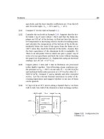
10.9 There is a radiant heater in the bottom of the box shown in
Fig. 10.27. What percentage of the heat goes out the top? What
fraction impinges on each of the four sides? (Remember that
the percentages must add up to 100.)
Figure 10.27 Configuration for
Prob. 10.9.
10.10 With reference to Fig. 10.12, find F
1–(2+4)
and F
(2+4)–1
.
10.11 Find F
2–4
for the surfaces shown in Fig. 10.28. [0.315.]
Figure 10.28 Configuration for
Prob. 10.11.
10.12 What is F
1–2
for the squares shown in Fig. 10.29?
586 Chapter 10: Radiative heat transfer
Figure 10.29 Configuration for
Prob. 10.12.
10.13 A particular internal combustion engine has an exhaust mani-
fold at 600
◦
C running parallel to a water cooling line at 20
◦
C.
If both the manifold and the cooling line are 4 cm in diame-
ter, their centers are 7 cm apart, and both are approximately
black, how much heat will be transferred to the cooling line by
radiation? [383 W/m.]
10.14 Prove that F
1–2
for any pair of two-dimensional plane surfaces,
as shown in Fig. 10.30, is equal to [(a + b) − (c + d)]/2L
1
.
This is called the string rule because we can imagine that the
numerator equals the difference between the lengths of a set
of crossed strings (a and b) and a set of uncrossed strings (c
and d).
Figure 10.30 Configuration for
Prob. 10.14.
10.15 Find F
1–5
for the surfaces shown in Fig. 10.31.
10.16 Find F
1–(2+3+4)
for the surfaces shown in Fig. 10.32.
10.17 A cubic box1montheside is black except for one side, which
has an emittance of 0.2 and is kept at 300
◦
C. An adjacent side
is kept at 500
◦
C. The other sides are insulated. Find Q
net
inside
the box. [2494 W.]
10.18 Rework Problem 10.17, but this time set the emittance of the
insulated walls equal to 0.6. Compare the insulated wall tem-
perature with the value you would get if the walls were black.
10.19 An insulated black cylinder, 10 cm in length and with an inside
diameter of 5 cm, has a black cap on one end and a cap with
Problems 587
Figure 10.31 Configuration for
Prob. 10.15.
Figure 10.32 Configuration for
Prob. 10.16.
an emittance of 0.1 on the other. The black end is kept at
100
◦
C and the reflecting end is kept at 0
◦
C. Find Q
net
inside
the cylinder and T
cylinder
.
10.20 Rework Example 10.2 if the shield has an inside emittance of
0.34 and the room is at 20
◦
C. How much cooling must be pro-
vided to keep the shield at 100
◦
C?
10.21 A 0.8 m long cylindrical burning chamber is 0.2 m in diameter.
The hot gases within it are at a temperature of 1500
◦
C and a
pressure of 1 atm, and the absorbing components consist of
12% by volume of CO
2
and 18% H
2
O. Neglect end effects and
determine how much cooling must be provided the walls to
hold them at 750
◦
C if they are black.
588 Chapter 10: Radiative heat transfer
10.22 A 30 ft by 40 ft house has a conventional 30
◦
sloping roof with
a peak running in the 40 ft direction. Calculate the temper-
ature of the roof in 20
◦
C still air when the sun is overhead
(a) if the roofing is of wooden shingles and (b) if it is commer-
cial aluminum sheet. The incident solar energy is 670 W/m
2
,
Kirchhoff’s law applies for both roofs, and the effective sky
temperature is 22
◦
C.
10.23 Calculate the radiant heat transfer from a 0.2 m diameter stain-
less steel hemisphere (ε
ss
= 0.4) to a copper floor (ε
Cu
= 0.15)
that forms its base. The hemisphere is kept at 300
◦
C and the
base at 100
◦
C. Use the algebraic method. [21.24 W.]
10.24 A hemispherical indentation in a smooth wrought-iron plate
has an 0.008 m radius. How much heat radiates from the 40
◦
C
dent to the −20
◦
C surroundings?
10.25 A conical hole in a block of metal for which ε = 0.5is5cmin
diameter at the surface and 5 cm deep. By what factor will the
radiation from the area of the hole be changed by the presence
of the hole? (This problem can be done to a close approxima-
tion using the methods in this chapter if the cone does not
become very deep and slender. If it does, then the fact that
the apex is receiving far less radiation makes it incorrect to
use the network analogy.)
10.26 A single-pane window in a large room is 4 ft wide and 6 ft high.
The room is kept at 70
◦
F, but the pane is at 67
◦
F owing to heat
loss to the colder outdoor air. Find (a) the heat transfer by
radiation to the window; (b) the heat transfer by natural con-
vection to the window; and (c) the fraction of heat transferred
to the window by radiation.
10.27 Suppose that the windowpane temperature is unknown in Prob-
lem 10.26. The outdoor air is at 40
◦
F and h is 62 W/m
2
Konthe
outside of the window. It is nighttime and the effective tem-
perature of the sky is 15
◦
F. Assume F
window−sky
= 0.5. Take
the rest of the surroundings to be at 40
◦
F. Find T
window
and
draw the analogous electrical circuit, giving numerical values
for all thermal resistances. Discuss the circuit. (It will simplify
your calculation to note that the window is opaque to infrared