Báo cáo lâm nghiệp: " Possibilities of using the portable falling weight deflectometer to measure the bearing capacity and compaction of forest soils" pptx
Bạn đang xem bản rút gọn của tài liệu. Xem và tải ngay bản đầy đủ của tài liệu tại đây (311.53 KB, 7 trang )
130 J. FOR. SCI., 56, 2010 (3): 130–136
JOURNAL OF FOREST SCIENCE, 56, 2010 (3): 130–136
e moto-manual technology of wood production
is often replaced by fully mechanized technologies.
e degree of mechanization is gradually increasing
and the timber harvesting and hauling machines do
the processing of an ever-higher percentage of annu-
al prescribed cut in the Czech Republic. e timber
logging and hauling machines are mainly farm trac-
tors, harvesters and forwarders (wheeled, trucked
and/or combined) in the Czech Republic. However,
the use of these technologies also entails soil dam-
age hazards. e most frequently occurring reasons
for damage to forest ecosystems may be improper
machine design, choice of inappropriate technology
or year season for the concerned site, technologi-
cal or work indiscipline or failure in mastering the
given technology. Even if we observe all basic rules
for the employment of machinery, we cannot avoid
some soil damage (even if minimal) because the
machine (even if properly used) affects negatively
the soil by travelling thereupon. We can observe
the greatest soil compaction (increased density)
immediately after the first machine pass after which
the soil density increases relatively steeply until the
fifth pass and then does not show any other marked
change (S, personal communication). Soils
damaged in this way return only very hardly to their
original condition.
Soil compaction entails the diminishing pore
size. Š (1978) claims the average pore size being
equal to 0.3–0.7 µm of the earth particle diameter.
Pores of diameter lesser than 0.2 µm fix water very
tightly and are as a rule filled with it. Pores under
0.01 mm are not available to root hairs and pores
under 0.001 mm are not inhabitable even by micro
-
Possibilities of using the portable falling weight
deflectometer to measure the bearing capacity
and compaction of forest soils
R. K, P. V, R. J
Department of Forest and Forest Products Technology, Faculty of Forestry and Wood Technology,
Mendel University in Brno, Brno, Czech Republic
ABSTRACT: e paper discusses possibilities of using the portable falling weight deflectometer to measure the bearing
capacity and compaction of forest soils. Within the study, measurements were made using manual penetrometer and
Loadman II portable falling weight deflectometer. To eliminate the extreme values, Grubbs’s test was used. e results
indicate that Loadman II deflectometer may be used to measure both the bearing capacity and compaction of forest
soils under the canopy as well as in transport lines. A significant difference was found between deflection of water-
unaffected sites and water-affected sites (12.08 and 2.31 mm, respectively). Measurements of bearing capacity after
removal of forest litter give far more precise details; however, the authors do not refuse the measurements without litter
removal, either. To determine the degrees of soil compaction, it is useful to measure the soil reaction time; to measure
the bearing capacity it is vital to measure deflection.
Keywords: deflection; E-module; PFWD; soil bearing capacity; soil compaction; soil reaction
Supported by the Ministry of Education, Youth and Sports of the Czech Republic, Project No. MSM 6215648902, and by the
Ministry of Agriculture of the Czech Republic, Project No. QH71159.
J. FOR. SCI., 56, 2010 (3): 130–136 131
organisms. e compaction of forest soils increases
the bulk soil density and if it exceeds the boundary
of 1.8 g.cm
–3
, the penetration of roots ceases to oc-
cur (D 1994), which is in accordance with the
finding that soil compaction leads to changes in the
growth of roots.
e compaction of soils closely relates to the for-
mation of ruts that later develop into water-bars and
initial places for the formation of erosion rills if the
transport line is led improperly. e risk of water
erosion also connects with sod stripping by skid
timber or by the lower frames of machines. e risk
of water erosion after the previous sod stripping due
to the insufficient adhesion of skidding mechanism
wheels is clearly evident at a slope angle of 33% (S-
, personal communication).
e impact of machine travel on soils (especially
fine-textured ones) started to be studied some
20 years ago and results of these studies are gen
-
erally known. e employment of harvesters and
forwarders entails a risk of soil disturbance namely
on water-logged, clay soils in which the passing
machines disturb the soil structure by compressing
large pores. In general, the compression of pores
unfavourably affects the soil structure, gas exchange
and water movement in both horizontal and vertical
direction. Uncontrolled soil erosion occurs on hill
slopes. e machine affects the soil by its weight,
i.e. by static pressure, but also by dynamic effects
(impacts) that may be far more dangerous in terms
of soil disturbance.
Š (1988, 1990), Š and Č (2009)
presented risks and methodological procedures for
the estimation of forest soil damage by erosion and
for the protection of forest soils against erosion due
to logging and hauling activities. One of the criteria
considerably affecting erosion is the bearing capacity
of soil. e bearing capacity of soil can be explained
in other words as the capacity of soil to sustain load.
By means of this variable, we can determine what
machines are acceptable in the given environment
with respect to soil disturbance. Nevertheless, the
bearing capacity of soil will not prevent the soil from
compaction. e degree of compaction (toughness)
can be established by means of deflectometers. How-
ever, deflectometers are primarily designed to detect
the quality of road base structures. eir advantage
consists in the fact that they are non-destructive and
capable of measuring lower layers of the roadbed.
Compared to conventional (large) falling weight
deflectors the portable (smaller) deflectometers
were designed for convenient handling. Another
reason for introducing portable deflectometers and
their advantage as compared with the conventional
ones is a markedly lower purchasing and operation
cost. In terms of applicability in the measuring of
forest soils, we can only consider the use of portable
deflectometers because the large conventional ones
cannot be properly moved within the stand. H
and K (1981) inform that portable falling
weight deflectometers (PFWD) are light devices
developed for the purpose of measuring the rigidity
of road body structural layers including sub-base
layers. e falling weight induces a non-destructive
shock wave spreading in the soil, which evokes the
reaction according to actual soil properties. e
difference of reaction is measured with velocity
pick-ups and with sensors measuring the acceler-
ated reaction of the surface (accelerometers). e
first model of PFWD Prima 100 was developed in
Denmark by Keros Technology. It was equipped
with exchangeable weights of 10, 15 and 20 kg and
with three exchangeable base plates of 100, 200 and
300 mm in diameter.
e next type of PFWD was Loadman, which was
developed by Al-Engineering Oy in Finland. is
deflectometer is today used by more than 60 research
organizations, universities and research workplaces
in Canada, Estonia, Finland, India, Israel, Italy, Pa-
kistan, Russia, Sweden, etc. Its variability is not as
high as that of Prima 100 because it has a standard
weight of 10 kg, reaction base plates of 132 and
300 mm in diameter and a standard falling weight
height of 800 mm. Its maximum dynamic load is
about 23 kN.
As compared to conventional deflectometers, the
portable models are due to their tiny design sus-
ceptible to the influence of many factors distorting
the measurement. S et al. (2005) compared
common conventional deflectometers with port-
able models in respect of their mutual correlation in
terms of measurement accuracy. In comparing the
portable and conventional deflectometer, correlation
coefficients ranged in general from 0.50 to 0.86 with
the portable deflectometers generally showing higher
module values. Including optimum moisture content
in the factors of field measurements, S et
al. (2005) found out that if the optimum moisture
content of the carriageway drops by 4%, the module
of elasticity might be affected up to 31 MPa.
W (1994) compared the conventional de-
flectometer with the Loadman and concluded that
the measurement with PFWD is not so accurate as
the measurement with conventional deflectometer
while measured values are higher and correlation
coefficient is markedly lower. He explains the low
correlation by the portable deflectometer having
lower weight and shock waves therefore penetrating
132 J. FOR. SCI., 56, 2010 (3): 130–136
only into the upper soil layers. Comparing the two
deflectometers he arrived at a correlation coefficient
of 0.78. e solution to this problem in literature sug-
gests that when a greater number of measurements
is taken and the extreme values are excluded, it is
possible to reach a higher correlation coefficient.
Comparing the Loadman and the common con-
ventional deflectometers, P (1997) ar-
rived at the following regression equation:
y = 1.06x + 10 (1)
where:
x – Loadman values of elasticity module in MPa,
y – elasticity module values of conventional deflecto-
meters.
e correlation coefficient was 0.5132 in this case
but the author unambiguously claims that using a
PFWD is a much faster method enabling to enlarge
the tested area as well as the frequency of measure-
ments. Loadman also facilitates an easier handling
of the instrument and an easier interpretation of
measuring results and it does not need calibration
for each type of material.
L et al. (2006) studied factors affecting the meas-
urement with portable deflectometers and pointed
out that a correct choice of the reaction base plate
is of vital importance. ey concluded that portable
deflectometers are the right choice to measure the
compaction of individual road base structures from
many aspects, namely due to their easy handling and
expeditious data acquisition.
M et al. (2007) analyzed the depth to which
stress effects can be detected. ey established that
the stress in lightweight PFWD (stress effect) could
be measured at a depth which is 1 to 1.5 times the
base plate diameter.
e application of PFWD for measuring the com-
paction of transport lines or forest soils has de facto
never been published. Only H et al. (2001)
reported in his paper that a deflectometer was used
for the measuring of transport lines on peat soils
in Finland and recommended to use a base plate of
300 mm in diameter and to measure soils without
the A horizon – with the denudated humus layer. He
also pointed out that it was useful to carry out a mini-
mum of two to three measurements at each site.
The goal of the present paper was to assess a
possibility of using the portable falling weight de-
flectometer for measuring the bearing capacity and
compaction of forest soils. e comparative measur-
ing instrument was a lightweight manual penetrom-
eter that had been used for measuring the bearing
capacity of forest soils in many cases.
MATERIAL AND METHODS
e measurement was made by using portable
falling weight deflectometer Loadman II USB and
Eijkelkamp manual penetrometer. e work pro-
cedure of measuring with penetrometer presented
by M et al. (1990) was modified for manual
penetrometer. Soil bearing capacity was measured
by using a cone type with 3.3 cm
2
cone base area
and 60° top angle. e values of soil resistance to the
penetrating point were measured with the pressure
gauge (instrument part). e penetration rate was
ca 2 cm per second – with equal pressure exerted
onto both handles.
e measuring with deflectometer was conducted
in two modes: at first, deflection values were meas-
ured 7 times at the same place where the humus layer
was not removed; then the measurement was made
twice at the same place with the removed humus
layer. e measurements were taken in various parts
of the forest stand so that values could be recorded
on slightly elevated sites (unaffected by water), on
water-affected sites, and on the transport line.
Firstly we removed all objects that could affect the
behaviour and results of the measurements (stones,
branches). en the instrument was placed at a verti-
cal position and its base was (if necessary) levelled
by twisting so that the entire instrument area was
properly seated on the soil. Prior to the first meas-
urement, the instrument was calibrated according to
the size of the reaction base plate. e diameter of
the reaction base plate was 132 mm and the calibra-
tion module of elasticity was chosen to be E 160 as
advised by the manufacturer. (Note: is value was
determined by the manufacturer to be a value with
the highest correlation towards conventional deflec-
tometers.) During the measurement, the instrument
was subtly held in vertical position at all times so that
the measurement could not be affected by the grip.
In cases with the removed litter, it was necessary to
assure a full seating of the instrument on the ground
surface by twisting movements.
All measurement results were stored in the instru-
ment’s memory under different locality identifica-
tions.
e sample plot where the measurements were
taken was subsequently subjected to the soil sam-
pling by means of physical Kopecky metal rings in
order to detect the actual soil moisture content. A
soil pit was excavated on the plot into a depth of
30 cm. In this soil pit, we levelled the walls to a flat
vertical position and took a sample of mineral soil by
using physical Kopecky metal rings. Wet soil sam-
ples were weighed in laboratory conditions with the
J. FOR. SCI., 56, 2010 (3): 130–136 133
accuracy of grams and inserted into an oven where
they were dried at a temperature of 103°C (+/–2°C)
for 17 hours. en the soil samples were weighed in
dry condition and moisture contents of soils in the
individual sites were calculated.
Gross errors were eliminated from values meas-
ured with the penetrometer and deflectometer by
using Grubbs’ test of gross errors (S 1984) and
the following calculations:
x
–
– x
min
T
min
= –––––––– (2)
σ
x
min
–
x
–
T
max
= –––––––– (3)
σ
where:
x – mean value,
x
max
– maximum value,
x
min
– minimum value,
σ – standard deviation.
If a T
max
or T
min
value exceeded the critical value
for Grubbs’ test at a corresponding degree of free-
dom and significance of 0.05 at a level of accuracy
+/–5%, it was established as a gross error. If such an
error occurred, it was eliminated from the data file
and the entire test was repeated.
Programme Curve Expert 1.3 was used to deter-
mine the most appropriate and most accurate cor-
relation.
RESULTS
Forest stand 146 D 8 and its characteristics were
as follows:
Area: 26.49 ha
Tree species representation: spruce 61%, larch 21%,
pine 17%, fir 1%
Forest type: 4K5
Primary management group of stands: 421
Spruce and larch – certified stand of phenotype
category B
Haplic Albeluvisol LUm with distinctly developed,
deep horizons and a fully developed humus sub-form
of typical moder. So-called absolute soil depth – D-ho-
rizon in the form of compact rock.
Site characterization: very mild gradient 3°, eastern
aspect
Soil profile characterization (B 2009):
0–1 L relatively fresh spruce litter
1–2 F partly decomposed spruce litter
2–4 H distinct signs of advanced decompo
-
sition and subsequent humification,
without recognizable structure
4–9 A 10YR 2/1, strongly humic, loamy,
loose, slightly moist, with high po-
rosity and medium biological activ-
ity, dense rooting
9–33 El 10YR 7.5/6, bleached, scaled struc
-
ture, easily decomposing, mildly
moist, with high porosity and indis-
tinct rooting
33–55 EB 5YR 5/8, sandy-loamy, moist, with me
-
dium porosity and indistinct rooting
55–75 Bt 5YR 4/6, loam to clay-loam, moist,
without mottle, packed
75 → D compact Devonian limestone.
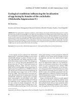
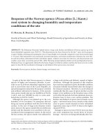
e curves of penetration resistance at depths
from 5 to 35 cm are presented in Fig. 1. e curve of
penetration resistance from the transport line of the
water-affected site was extremely high. A subsequent
inquiry revealed that the transport line was reno-
vated in the past, which resulted in entirely different
soil penetration resistance values. e curves of soil
resistance are regression equations of the measured
values, which were as follows:
water-unaffected
water-affected
water-unaffected in the rut
water-affected in the rut
Depth (cm)
Specific force (N)
0 5 10 15 20 25 30 35 40
900
800
700
600
500
400
300
200
100
0
Fig. 1. Curves of soil penetration
resistance
134 J. FOR. SCI., 56, 2010 (3): 130–136
108.369
+ 1.0934x
y = ––––––––––––––––––––– (4)
1 – 0.0531x + 0.000923x
2
for water-unaffected sites (standard deviation
0.886):
164.223 + 0.550x
y = ––––––––––––––––––––––– (5)
1 – 0.0477x + 0.000744x
2
for water-unaffected sites at the transport line
(standard deviation 0.818):
260.260 + 5.406x
y = ––––––––––––––––––––––– (6)
1 – 0.00893x – 0.000444x
2
for water-affected sites (standard deviation 0.646):
y = 352.504x
0.243
(7)
for water-affected sites at the transport line (stand-
ard deviation 0.435).
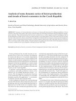
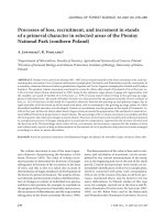
A multiple measurement on one site with litter
is illustrated in Fig. 2. e measured values have a
decreasing trend and at the seventh measurement
they reach approximately a half value of the initial
measurement. Deflection in the transport line rut is
at all times higher than deflection measured outside
the transport line in both cases, i.e. on sites unaf-
fected by water and on water-affected sites.
Multiple measurements on one site without litter
are illustrated in Fig 3. e measured values do not
show any distinct changes. Deflection in the transport
line rut is at all times higher than deflection measured
outside the transport line in both cases, i.e. on sites
unaffected by water and on water-affected sites.
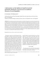
The results of measurements on different sites
within the forest stand after the removal of litter are
shown in Fig. 4. e left side of the diagram contains
values measured on water-unaffected sites and the
right side of the diagram contains values measured
on water-affected sites. Average deflection on water-
unaffected and water-affected sites was 12.08 mm
and 2.31 mm, respectively.
DISCUSSION
e measuring of deflection without litter removal
showed considerably unbalanced results with a de-
unaffected
affected
unaffected in the rut
affected in the rut
Measurement
Deflection (mm)
1 2 3 4 5 6 7
14
12
10
8
6
4
2
0
unaffected
affected
unaffected in the rut
affected in the rut
Measurement
Deflection (mm)
1 2 3 4 5 6 7
18
16
14
12
10
8
6
4
2
0
Fig. 2. Multiple deflection measurement on
sites with litter
Fig. 3. Multiple deflection measurement on
sites after litter removal
J. FOR. SCI., 56, 2010 (3): 130–136 135
creasing trend on all four sites. is is presumably
caused by the properties of litter (surface layer)
changing due to the falling weight. Litter thickness
was approximately 4 cm, and if the capacity of deflec-
tometer is to measure into a depth of ca 1.5 multiple
of reaction area (M et al. 2007) it is very signifi-
cant with respect to the measured profile. Neverthe-
less, the authors do not condemn the measurement
with litter. Harvesters pass through the forest stand
usually only once and litter can markedly affect the
total bearing capacity of soil. The measurement
without litter appears to provide a more accurate
determination of soil bearing capacity.
e measurement of soil bearing capacity after
litter removal outside the transport line and on the
transport line shows apparent differences. e soil
that is compacted or has a higher bearing capacity
reacts more readily to the weight which acquires
higher energy after the fall, i.e. higher deflection.
Water-affected sites (less compacted soils with lower
bearing capacity) readily absorb the energy and the
measure of deflection is therefore lower.
If we compare the measurement with penetrom-
eter and deflectometer, we can follow the degree of
soil bearing capacity in the following order (from the
most bearing/compacted ones):
– measured with penetrometer: water-affected sites
on the transport line, water-unaffected sites on
the transport line, water-unaffected sites outside
the transport line, water-affected sites outside the
transport line;
– measured with deflectometer: water-unaffected
sites on the transport line, water-affected sites on
the transport line, water-unaffected sites outside
the transport line, water-affected sites outside the
transport line.
e authors maintain that the penetrometer meas-
urements are distorted due to the previous transport
line renovation but in terms of the soil bearing ca-
pacity, a more important role will be that of water-af-
fection. is transport line was by sight less bearing
than the transport line on the water-unaffected site
although the soil moisture content amounted to 19%
at the multiple measurement without litter as well as
with litter on the water-unaffected site while on the
water-affected site it was 19.6%.
As to the identification of compaction and estab-
lishment of compaction degree, the authors maintain
that acceleration (soil reaction time) can also be
used. In the transport lines, the soil reaction time
was markedly shorter and ranged in the order of
half-reaction times of non-compacted soil.
All these theories lead the authors to a further and
more in-depth exploration after which it would be
possible to express a hypothesis that the degree of
soil bearing capacity can be established in depend-
ence on soil moisture content and that soil reaction
time depends on soil compaction.
R ef erenc es
B J. (2009): Compaction of the surface horizons of
selected forest soils at the Training Forest Enterprise
Masarykův les Křtiny by means of the dynamic penetra-
tion test. [MSc. esis.] Brno, MZLU, LDF: 39. (in Czech)
D J. (1994): Forest soil compaction during timber haul-
ing: skidder LKT 40. Forestry, 40: 482–485. (in Slovak)
H R., R M., S M. (2001): Avail-
able at />publications/31/assessme.pdf (accessed on February 20,
2009)
H R.D., K W.D. (1981): An Introduction to
Geotechnical Engineering. New Jersey, Prentice Hall:
206–212.
L D.F., L C.C., L J.D. (2006): Factors affecting port-
able falling weight deflectometer measurements. Journal
of Geotechnical and Geoenvironmental Engineering, 132:
804–808.
unaffected affected
Measurement
Deflection (mm)
0 10 20 30 40 50 60
16
14
12
10
8
6
4
2
0
Fig. 4. Deflection measured on different sites within
the stand after litter removal
136 J. FOR. SCI., 56, 2010 (3): 130–136
M M., Ť O., C M. (1990): Field Soil Tests.
Bratislava, Alfa: 303. (in Slovak)
M P.K., R R.V., M M.A. (2007): Measure-
ment of soil stress and strain using in-ground instrumenta-
tion. In: Proceedings of the ASCE Geoinstitute GeoDenver
Conference, Denver: 10.
P B. (1997): Evaluation of non-destructive in situ
tests for unbound granular pavements. IPENZ Transac-
tions, 24: 12–17.
S L. (1984): Applied Statistics: A Handbook of Tech-
niques. New York, Springer-Verlag: 253.
S B.C., H D.N., K M.A. (2005): Port-
able Falling Weight Deflectometer Study. Maine, University
of Maine Orono: 331.
Š F. (1988): Estimating risk of logging erosion on forest
lands. Lesnická práce, 67: 490–493. (in Czech)
Š F. (1990): Logging systems and soil erosion on clearcuts
in mountain forests. Forestry, 36: 895–910.
Š F., Č V. (2009): Forest Land Conservation
Guidelines for Soil Erosion Control. Strnady, Výzkumný
ústav lesního hospodářství a myslivosti: 54. (in Czech)
Š R. (1978): Soil, the Base of Forest Production. Bratislava,
Príroda: 238. (in Slovak)
W A.M. (1994): Non-Destructive Pavement Testing
Equipment: Loadman, Falling Weight Deflectometer, Ben-
kelman Beam, Clegg Hamer. Christchurch, University of
Canterbury, Department of Civil Engineering: 19.
Received for publication June 17, 2009
Accepted after corrections August 10, 2009
Corresponding author:
Ing. R K, Ph.D., Mendelova univerzita v Brně, Lesnická a dřevařská fakulta, Zemědělská 3,
613 00 Brno, Česká republika
tel.: + 420 545 134 528, fax: + 420 545 211 422, e-mail: