Research Issues in Systems Analysis and Design, Databases and Software Development phần 8 ppsx
Bạn đang xem bản rút gọn của tài liệu. Xem và tải ngay bản đầy đủ của tài liệu tại đây (813.89 KB, 29 trang )
192 Cai
Copyright © 2007, IGI Global. Copying or distributing in print or electronic forms without written permission
of IGI Global is prohibited.
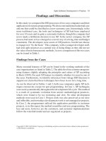
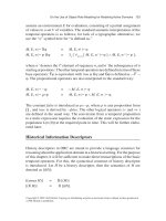
by systematically reconciling various perspectives, improving the processes,
and controlling the product data and organizational structure.
Perspective Modeling
The perspective modeling mainly consists of building the concept model
and the perspective model. While the process model depicts the tangible
activities of the project, the concept model and perspective model track the
knowledge evolution and changes of social behaviors.
The rst step is to generate the concept structure hierarchy. A concept model is
a hierarchical structure that represents the organization of the ontology (Huhns
& Stephens, 1999; Staab, Schnurr, Studer, & Sure, 2001) that stakeholders
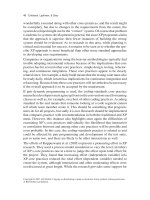
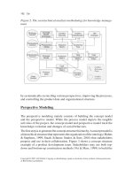
propose and use in their collaboration. Figure 3 shows a concept structure
example of a product development team. Stakeholders may use both top-
down and bottom-up construction methods (Vet & Mars, 1999) to build the
Figure 2. The sociotechnical analysis methodology for knowledge manage-
ment
Perspective
Model
Distance
Matrix
Concept
Model
(Ontology)
Conflict
Intensity
Clustering
Tree
Conflict
Classification
Process
Model
Incidence
Matrix
Task
Assignment
Matrix
Task
Perception
Matrix
Task
Agreement
Index
Product
Data
CM
Analysis
Perspective
Control
Ontology
Control
Data
Control
Process
Control
Organization
Control
Conflict
Detection
Point
Conflict
Control
Modeling and Analyzing Perspectives to Support Knowledge Management 193
Copyright © 2007, IGI Global. Copying or distributing in print or electronic forms without written permission
of IGI Global is prohibited.
concept structure. It is possible to apply some templates (e.g., product function
template, organizational template, conict types template, etc.) to clarify the
concepts. These templates act as the contend-based skeletons for organizing
the external information that stakeholders may share with others.
When stakeholders propose new concepts, the concept structure is updated
and is used to systematically organize these concepts and their relationships.
Since a stakeholder should rst consider whether there are same or similar
concepts in the structure, only the novel concepts can be specied and added.
The concepts involved within the collaboration are classied into two types.
Shared concepts are those that have been well dened from previous projects.
They have widely accepted meaning shared among the stakeholders (e.g.,
in Figure 3, Function Requirements, Product, and Organization are shared
concepts). Private concepts are perceived only by some particular stakehold-
ers. Their names or meanings are not expressed around the group. If a group
of people have a shared purpose toward a concept, everyone will be asked
Figure 3. A concept structure built by stakeholders in a collaborative design
project
Produ
ct
Function Stru
cture
Function list
Mechanical
Behavi
or
Energy Consumption
Impact to environment
Noise ratio
S3
Technical Decision
Design Methodology
Design Process
Domain
s
Function Requirements
Design Parameter
Process Variable
Events
Tasks
Dependency
Resource
S2
S4
Customer Needs
Axioms
Independent Axiom
In
form
ation Axiom
FR1
FR2
S1
Looking
Organization
Norm Structure
Employee
Company Regulation
ISO9000
Relationship specified by individual
Relationship defined by group
Freezing
system
Shared concept
Private concept
194 Cai
Copyright © 2007, IGI Global. Copying or distributing in print or electronic forms without written permission
of IGI Global is prohibited.
to view it. After the concepts are identied, the dependencies among these
concepts can be further claried by stakeholders.
The second step is to generate the perspective model. A perspective model is
the special information representing the status of a stakeholder’s perspective at
a certain time. A perspective model consists of the purpose (i.e., the intention
to conduct certain actions), context (i.e., the circumstances in which one’s
action occurs), and content (i.e., what one knows and understands) that the
stakeholder uses to access the external knowledge and to expose the internal
knowledge. In information systems, the perspective model can be depicted
as a data format relating to other information entities.
Our research develops a format for representing perspectives and a procedure
to capture, generate, and analyze perspective models. Given the well-orga-
nized structure of concepts, it is feasible to ask the stakeholders to build the
perspective-model state diagrams (PMSDs) at a certain time. A stakeholder’s
PMSD attempts to depict the explicit relationships among his or her concepts
(including the shared concepts and private concepts) and purpose, content,
and context information. The concepts listed in the PMSD are categories
of perspective contents. Using the concept structure to generate the PMSD
provides a structured way for us to systematically compare and examine the
perspective differences among stakeholders.
Each concept of the concept model can be associated with a stakeholder by
a set of purposes, contexts, and contents. The operation is to ask the stake-
holders to do the following.
First, relate this concept to their purposes. A stakeholder is able to specify his
or her purpose within the project for a given concept. There might be more
than one purpose involved. For an abstract concept, the purpose could be
more general. For a specic concept, the purpose could be detail.
Second, specify the relationships of this concept with other concepts based
on his or her context. If there is a new concept generated, add it to the PMSD
architecture and set it as a private concept.
For each concept, declare or relate his or her own knowledge, document,
and data about that concept and put them as the elements of the content as-
sociated with that concept.
Therefore, a PMSD is the picture that depicts a snapshot of a stakeholder’s
perception of concepts. It embodies his or her related purposes, context, and
content. In a collaboration-support system, a PMSD is represented as XML
(extensible markup language) formats to facilitate analysis.
Modeling and Analyzing Perspectives to Support Knowledge Management 195
Copyright © 2007, IGI Global. Copying or distributing in print or electronic forms without written permission
of IGI Global is prohibited.
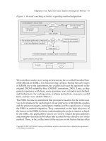
The third step is to conduct the perspective analysis. By comparing and
analyzing stakeholders’ perspective models, it is possible to determine the
degree of agreement among their opinions during their interaction. As shown
in Figure 4, given the PMSDs for certain stakeholders, we can ask them to
review others’ perspective models. The review information is used to com-
pare the perspective models and determine the similarity of two stakehold-
ers’ perspectives toward a shared concept. We can also aggregate multiple
stakeholders’ perspective models and compare their general attitudes at dif-
ferent levels of abstraction. Furthermore, we can track the evolution of the
perspective model based on the clustering analysis results. The procedure is
called perspective analysis (Figure 4).
The rst step is to determine the inconsistency (i.e., the distance) among a
group of perspective models. There are two approaches: the intuitive approach
and the analytical approach. The intuitive approach relies on the insights of
the stakeholders. The analytical approach uses mathematical algorithms to
derive the distance through positional analysis, which is based on a formal
method used in social network analysis (Wasserman & Faust, 1994). This
approach views the perspective models of a group of stakeholders toward a
single concept as a network of opinions associated with each other. In this
network, a stakeholder, who possesses a perspective model, has relationships
with others’ perspective models. We dene these relationships as their per-
ceptional attitudes toward each other. A group of perspective models toward
a given concept are placed as a graph (i.e., a PM network). Two perspective
models are compatible (or similar) if they are in the same position in the
network structure. In social network analysis, position refers to a collection
of individuals who are similarly embedded in networks of relations. If two
perspective models are structurally equivalent (i.e., their relationships with
other perspective models are the same), we assume that they are purely
compatible and there are no detectable differences. That implies that they
have the same perception toward others, and others have same perception
toward them.
A distance matrix is derived for each PM network. It represents the situation of
perspective compatibility among a group of stakeholders for a given concept.
We can also compare stakeholders’ perspective models for multiple concepts
by measuring the structural equivalence across the collection of perspective
model networks. Perspective distance matrices serve as the basis for cluster
analysis. Hierarchical clustering is a data analysis technique that is suited
for partitioning the perspective models into subclasses. It groups entities into
196 Cai
Copyright © 2007, IGI Global. Copying or distributing in print or electronic forms without written permission
of IGI Global is prohibited.
subsets so that entities within a subset are relatively similar to each other.
Hierarchical clustering generates a tree structure (or a dendrogram), which
shows the grouping of the perspective models. It illustrates that the perspective
models are grouped together at different levels of abstraction (Figure 4).
The cluster tree exposes interesting characteristics of the social interactions.
Within a collaborative project, the participants of the organization cooperate
and build the shared reality (i.e., the common understanding of the stake-
holders toward certain concepts) in the social interaction process (Berger &
Luckman, 1966). Understanding the process of building shared realities is the
key to managing social interactions. The shared reality can be represented by
the abstraction of close perspective models among a group of stakeholders.
As a matter of fact, the cluster tree depicts the structures of the shared real-
ity since a branch of the clustering tree at a certain level implies an abstract
perspective model with certain granularity. The height of the branch indicates
the compatibility of the leaf perspective models. A cluster tree with simple
structure and fewer levels implies that all of the perspective models have
similar attitudes (or positions) toward others.
Figure 4. The perspective analysis procedure
Perspective Model
Perspective Review
Perspective
Distance Matrix
Cluster Analysis
Perspective
Abstraction Model
Perspective
Evolution Model
PM Network
Concept
Concept
Concept
P1
P2
P4
P7
P3
P6
P5
P1.xml
P2.xml
Dendrogram for averagelinkage cluster
analysis
L2 dissimilarity measure
0
.837122
1 2 6 3 4 5 7
…
Pn.xml
PMSDs
Concept
Model
PM
Network
Cluster
Tree
Modeling and Analyzing Perspectives to Support Knowledge Management 197
Copyright © 2007, IGI Global. Copying or distributing in print or electronic forms without written permission
of IGI Global is prohibited.
While the perspective models are changing, the clustering analysis can be
used as a systematic way to depict the transformation of the perspective
models. The change of the cluster trees at different stages of collaboration
reveals the characteristics of perspective evolution. Investigating the changes
of the topological patterns of the clustering trees leads to ways to interfere
in the perspective evolutions.
Conict Management
Given the condition that the social interactions are analytically measured,
control mechanisms can be derived to manage the evolutions of the perspective
models and therefore to support collaboration. Theses mechanisms could be
selected and used by the group managers or coordinators to control conicts.
They can be classied into the following strategies.
Process Control
The perspective analysis can be performed for all of the stakeholders who
might act on or inuence a task. By evaluating their perspective compat-
ibility and the execution feasibility of future tasks, which are in the plan but
have not been conducted yet, we can prevent some conicts by noticing their
potential existence earlier. By providing certain information to stakeholders,
it is possible to change the perception matrix and therefore to increase the
perspective consistency of a task. It is possible to directly adjust the sequences
and dependencies among the tasks to maintain the integrity of the opinions
of stakeholders.
Perspective Control and Ontology Control
First, it is possible to directly inuence stakeholders’ perspectives (their con-
tent, purpose, and context) to maintain the integrity and compatibility of the
opinions toward a certain concept or task. Analyzing social interactions will
identify the perspective models with low similarities and reveal the conicts
clearly. Thus, we can focus on the stakeholders who have singular perspec-
tives and understand their rationale. Second, communication channels can
be built to increase the interaction opportunities among stakeholders with
198 Cai
Copyright © 2007, IGI Global. Copying or distributing in print or electronic forms without written permission
of IGI Global is prohibited.
different perspective models. The group can manipulate the concept structure
through clarifying the meanings and denitions of critical concepts so that
people have shared understanding. It is also feasible to serve stakeholders
with different concepts to isolate their perspectives. An opposite way is to
use conicting perspectives as means to enhancing brainstorming and in-
novation. Third, strategies can be derived to manage the conicts through
inuencing stakeholders’ information access and comprehension. Possible
solutions include providing suitable trainings based on their perspectives and
the job requirements, assisting the critical stakeholder to review the relevant
information during certain conicting tasks, and recording the discussions
about the shared concept for future reuse.
Organization Control
The clustering tree shows the grouping features of stakeholders’ perspectives.
Using different organizational structures will change the communication
channels and the perception distances. If two stakeholders are separated into
different groups, the possibility of interaction will decrease. We can change
the task assignment or modify stakeholder’ roles to affect their contexts. It
is even possible to add or remove stakeholders associated with a certain task
to avoid the conicting situation or to move the stakeholders with similar
perspectives together.
Data and Information Control
This control mechanism is to affect the conicts through appropriately provid-
ing and handling external data and information that will be accessed by the
stakeholders. Examples are to use consistent checking and version-control
mechanisms to maintain the product data integrity, to track the changes of
shared data and information by referencing to the perspective changing, and to
map the shared data and information to perspective models so that the system
realizes the specic impact of the conicts toward the working results.
Modeling and Analyzing Perspectives to Support Knowledge Management 199
Copyright © 2007, IGI Global. Copying or distributing in print or electronic forms without written permission
of IGI Global is prohibited.
Building Electronic Collaboration Support Systems Using the Perspective
Modeling Approach
The perspective modeling and analyzing methodology provides a theoretical
basis for building new knowledge management systems. The STARS system
is a prototype system to support collaboration over the Internet. It is also
developed as an experimental apparatus for testing the research. The system
implements the process modeling, perspective modeling, and sociotechnical
analysis methodologies. On the other hand, it collects process and perspec-
tive data once stakeholders use it as a collaboration tool. By investigating
the collected experimental data, we can determine the effectiveness of the
approach and therefore improve it.
The STARS system provides a Web-based environment that supports the
collaboration process representation, conict management, and knowledge
integration within a project team. Stakeholders declare, share, and modify
their perspective models on the Web. The perspectives models are analyzed
in the system and stakeholders’ roles in the collaboration tasks are depicted.
Internet (www, TCP/IP, HTML, XML )
HTTP
Perspective
Data
Organization
Data
Product
Data
Process
Data
Conflict
Management
Process
Management
Organization
Management
Product
Management
Process
Builder/Viewer
Perspective Model
Builder/Viewer
Organization
Viewer
Conflict
Viewer
Servlets/JSP
DBMS
GUI
/View
Control
Applet
Client
HTML
JScript
SQL
Process
Task/State
Model
Concept
EJB
Perspective
EJB
Conflict
Data
Stakeholder
EJB
Conflict
EJB
Product
EJB
Perspective
Management
Stakeholders
Product
Builder/Viewer
XML
XML
Enterprise
Connector
WAP
WAP
Service
Manager/Prov ider
SOAP
CDPN
Simulator
CDPN
Audit
CDPN
Rendering
Applet
Client
HTML
JScript
CDPN
Simulator
CDPN
Audit
CDPN
Rendering
Figure 5. STARS system architecture
200 Cai
Copyright © 2007, IGI Global. Copying or distributing in print or electronic forms without written permission
of IGI Global is prohibited.
The system implements the functional modules (e.g., perspective manage-
ment, process management, conict management, etc.) by using J2EE1.4 and
Web services technologies (Figure 5). It provides methods to detect, analyze,
and track the conicts during collaboration. It also supports the business-to-
business process communications through SOAP and UDDI.
Figure 6 shows the knowledge perspective management module that allows
stakeholders to declare and review their perspective information according
to a concept structure tree. The system can analyze the perspective models,
detect and predict conicts, and suggest possible control strategies. The pro-
cess management system of STARS uses an XML-based process modeling
tool for process planning, scheduling, simulation, and execution. It helps the
stakeholders notice what is happening and who is doing what at any time.
Stakeholders declare their perspectives during each step of the process. The
system determines the conict ratio of each task based on the perspective
analysis.
Groups of designers, business analysts, and consultants working in a U.S.
national construction research institute have been using STARS in their
Figure 6. The perspective-management and conict-management modules
of STARS
Modeling and Analyzing Perspectives to Support Knowledge Management 201
Copyright © 2007, IGI Global. Copying or distributing in print or electronic forms without written permission
of IGI Global is prohibited.
small projects. Feasibility and computability of the analysis algorithms were
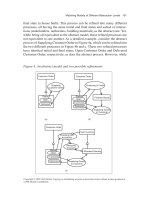
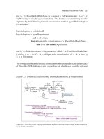
proved. Figure 7 depicts an example of using STARS to solve a conict
problem through perspective analysis. Before using STARS, similar cases
as described below often happened in one design team:
Within a design project, at the rst meeting, the client’s design consultant
stated that the building was to be placed at a location on the site. The archi-
tect listened to the client’s reasoning but noted that this location is not ideal
from either an aesthetic or a functional point of view, since it would be too
close to a major road intersection.
The STARS perspective analyzing functions helped users notice the de-
pendencies and differences of views among the stakeholders. The conict
was detected by tracking and mapping the perspective models of the three
stakeholders. STARS compared the perspective models at an early stage of
Figure 7. An example of detecting conicts from perspective analysis
Gather client space usage
information;
Space allocation require
me
nt
an
al
ys
is
;
Gather clien
t
space usage
information;
Space allocation requirement
analysis;
Technical Decision
Personnel schedule;
Personnel loads;
Space usage;
Building location;
Personnel schedule;
Personnel loads;
Space usage;
Building location;
Product
Space allocation
;
Space usage;
Building environ
me
nt;
Building regulation;
Building shape, material
Space allocation;
Space usage;
Building environment;
Building regulation;
Building shape,
ma
terial
Technical Decision
Waiting for the layout from
the design consultan
t
Wa
iting for the la
yo
ut fro
m
the desi
gn consu
ltant
Product
R
ep
ort to owner;
View clients as information
source;
R
ep
ort to owner;
View clients as information
source;
Organization
The role is not well defined yet
The role is not well defined yet
Organization
Building location is
chosen by users.
Us
er pre
fer locati
on
A;
Building should not be
very near to road
intersection.
Building location not
av
ailabl
e
Design Consultant
Architect
Building spa
ce usage
not available
Space usage;
Personnel schedule;
Functionality;
Lookin
g;
Space usage;
Personnel schedule;
Functionality;
Lookin
g;
Product
Client
Organization
Matrix structure organization.
Matrix
s
tructure organization.
location A is near road;
location B is far from road;
Only A and B and C are
feasible
Dependency noticed
Conflict noticed
202 Cai
Copyright © 2007, IGI Global. Copying or distributing in print or electronic forms without written permission
of IGI Global is prohibited.
the design. Although there was no direct meeting between the design con-
sultant and the architect, the system detected a potential conict during the
design process.
The stakeholders who participated in the experiment considered that using
the perspective modeling methodologies could accelerate their learning pro-
cess and detect conicts earlier in their collaborative projects. The causes of
breakdowns of collaboration are more comprehensible when applying the
analysis methodologies.
Conclusion
This chapter presents a systematic methodology to support knowledge man-
agement by modeling and analyzing stakeholders’ perspectives and their
social interactions within collaborative processes. This approach provides
methods for capturing perspectives and understanding their relationships to
facilitate the control of the evolution of the shared insights. It avails knowl-
edge management and conict management by systematically facilitating the
manipulation of the process, the perspectives, the organizational structure, and
the shard data and information. The STARS system was built to improve the
coordination among stakeholders. Its perspective modeling function provides
an efcient way for stakeholders to understand the meanings and improve
coordination during their collaboration over the Internet.
This research has some limitations. First, the closed-loop perspective man-
agement methodology requires stakeholders to be actively involved in the
building and updating of perspective models. This might be overkill when
the group is already very efcient and stable. Second, using the perspective
analysis requires the computing tool and thus introduces a higher level of
complexity. The system users have to be able to honestly and clearly specify
their understandings toward the concepts and others’ perspectives. In the fu-
ture, the perspective analysis model can be improved by applying advanced
statistics and econometrics techniques. It is also important to generate dy-
namic modeling methods to dene the relationships between the evolution
of perspective models and the quality of online collaboration.
Modeling and Analyzing Perspectives to Support Knowledge Management 203
Copyright © 2007, IGI Global. Copying or distributing in print or electronic forms without written permission
of IGI Global is prohibited.
References
Alavi, M., & Leidner, D. E. (2001). Review: Knowledge management and
knowledge management systems: Conceptual foundations and research
issues. MIS Quarterly, 25(1), 105-136.
Arias, E. G., Eden, H., Fischer, G., Gorman, A., & Scharff, E. (2000). Tran-
scending the individual human mind-creating shared understanding
through collaborative design. ACM Transactions on Computer-Human
Interaction, 7(1), 84-113.
Becerra-Fernanaez, I., & Sabherwal, R. (2001). Organizational knowledge
management: A contingency perspective. Journal of Management In-
formation Systems, 18(1), 23-55.
Berger, P., & Luckman, T. (1966). The social construction of reality a treatise
in the sociology of knowledge. New York: Doubleday.
Briggs, R. O., Vreede, G J., & Nunamaker, J. F., Jr. (2003). Collaboration
engineering with thinkLets to pursue sustained success with group
support systems. Journal of Management Information Systems, 19(1),
31-64.
Carley, K. M., & Prietula, M. J. (1994). ACTS theory: Extending the model
of bounded rationality. In Computational organization theory (pp. 55-
88). UK: Lawrence Erlbaum Associates.
Chae, B., Koch, H., Paradice, D., & Huy, V. V. (2005). Exploring knowledge
management using network theories: Questions, paradoxes, and pros-
pects. The Journal of Computer Information Systems, 45(4), 62-15.
Chung, C W., Kim, C R., & Dao, S. (1999). Knowledge and object-oriented
approach for interoperability of heterogeneous information management
systems. Journal of Database Management, 10(3), 13-25.
Clancey, W. J. (1993). Guidon-manage revisited: A socio-technical systems
approach. Journal of Articial Intelligence in Education, 4(1), 5-34.
Clancey, W. J. (1997). The conceptual nature of knowledge, situations, and
activity. In P. Feltovich, R. Hoffman, & K. Ford (Eds.), Human and
machine expertise in context (pp. 247-291). CA: AAAI Press.
Dym, C. L., & Levitt, R. E. (1991). Toward the integration of knowledge for
engineering modeling and computation. Engineering with Computers,
7(1), 209-224.
204 Cai
Copyright © 2007, IGI Global. Copying or distributing in print or electronic forms without written permission
of IGI Global is prohibited.
Earl, M. J. (2001). Knowledge management strategies: Toward a taxonomy.
Journal of Management Information Systems, 18(1), 215-233.
Easley, R. F., Sarv, D., & Crant, J. M. (2003). Relating collaborative technol-
ogy use to teamwork quality and performance: An empirical analysis.
Journal of Management Information Systems, 19(4), 247-268.
Erickson, T., & Kellogg, W. A. (2000). Social translucence: An approach to
designing systems that support social processes. ACM Transactions on
Computer-Human Interactions, 7(1), 59-83.
Hanson, M., Nohira, N., & Tierney, T. (1999). What is your strategy for
managing knowledge? Harvard Business Review, 106-116.
Hardjono, T. W., & van Marrewijk, M. (2001). The social dimensions of busi-
ness excellence. Corporate Environmental Strategy, 8(3), 223-233.
Huhns, M. N., & Stephens, L. M. (1999). Personal ontologies. IEEE Internet
Computing, 3(5), 85-87.
Kannapan, S., & Taylor, D. (1994). The interplay of context, process, and
conict in concurrent engineering, Journal of Concurrent Engineering
Research and Applications, 2(1), 183-196.
Kwan, M. M., & Balasubramanian, P. (2003). Process-oriented knowledge
management: A case study. Journal of Operational Research Society,
54(1), 204-211.
Lee, H., & Choi, B. (2003). Knowledge management enablers, processes, and
organizational performance: An integrative view and empirical examina-
tion. Journal of Management Information Systems, 20(1), 179-228.
Lu, S. C Y., & Cai, J. (2001). A collaborative design process model in the
sociotechnical engineering design framework. Articial Intelligence for
Engineering Design, Analysis and Manufacturing, 15(1), 3-20.
Nonaka, I., Reinmoeller, P., & Senoo, D. (1998). The “ART” of knowledge:
Systems to capitalize on market knowledge. European Management
Journal, 16(6), 673-684.
Nonaka, I., & Takeuchi, H. (1995). The knowledge-creating company. New
York: Oxford University Press.
O’Leary, D. E. (1998). Enterprise knowledge management. IEEE Computer,
54-61.
Preece, A., Flett, A., & Sleeman, D. (2001). Better knowledge management
through knowledge engineering. IEEE Intelligent Systems, 36-43.
Modeling and Analyzing Perspectives to Support Knowledge Management 205
Copyright © 2007, IGI Global. Copying or distributing in print or electronic forms without written permission
of IGI Global is prohibited.
Reimer, U., Margelisch, A., & Staudt, M. (2000). EULE: A knowledge-based
system to support business processes. Knowledge-Based Systems, 13,
261-269.
Rouse, W. B. (2001). Need to know: Information, knowledge, and decision
making. IEEE Transactions on Systems, Man, and Cybernetics. Part
C: Applications and Reviews, 32(4), 282-292.
Shaw, D., Ackermann, F., & Eden, C. (2003). Approaches to sharing knowl-
edge in group problem structuring. Journal of the Operational Research
Society, 54, 936-948.
Siau, K. (1999). Information modeling and method engineering: A psycho-
logical perspective. Journal of Database Management, 10(4), 44-50.
Sowa, J. F., & Zachman, J. A. (1992). Extending and formalizing the frame-
work for information systems architecture. IBM System Journal, 31(3),
590-616.
Spender, J. C. (1996). Making knowledge the basis of a dynamic theory of
the rm. Strategic Management Journal, 17, 45-62.
Staab, S., Schnurr, H P., Studer, R., & Sure, Y. (2001). Knowledge processes
and ontologies. IEEE Intelligent Systems, 26-34.
Tanriverdi, H. (2005). Information technology relatedness, knowledge
management capability, and performance of multibusiness rms. MIS
Quarterly, 29(2), 311-335.
Vet, P. E., & Mars, N. J. (1998). Bottom-up construction of ontologies. IEEE
Transaction on Knowledge and Data Engineering, 10(4), 513-526.
Wasserman, S., & Faust, K. (1994). Social network analysis: Methods and
applications. New York: Cambridge University Press.
Zack, M. H. (1999). Managing codied knowledge. Sloan Management
Review, 40(4), 45-58.
206 Halpin
Copyright © 2007, IGI Global. Copying or distributing in print or electronic forms without written permission
of IGI Global is prohibited.
Chapter VIII
Modality of Business Rules
Terry Halpin, Neumont University, USA
Abstract
A business domain is typically subject to various business rules. In practice,
these rules may be of different modalities (e.g., alethic and deontic). Alethic
rules impose necessities, which cannot, even in principle, be violated by the
business. Deontic rules impose obligations, which may be violated, even
though they ought not to be. Conceptual modeling approaches typically
conne their specication of constraints to alethic rules. This chapter dis-
cusses one way to model deontic rules, especially those of a static nature. A
formalization based on modal operators is provided, and some challenging
semantic issues are examined from both logical and pragmatic perspectives.
Because of its richer semantics, the main graphic notation used is that of
object-role modeling (ORM). However, the main ideas could be adapted for
UML and ER as well. A basic implementation of the proposed approach has
been prototyped in Neumont ORM Architect (NORMA), a software tool that
supports automated verbalization of both alethic and deontic rules.
Modality of Business Rules 207
Copyright © 2007, IGI Global. Copying or distributing in print or electronic forms without written permission
of IGI Global is prohibited.
Introduction
In the wider sense, an information system corresponds to a business domain
or universe of discourse rather than an automated system. Business domains
are constrained by various business rules, which specify required or desirable
states of affairs or behavior. Business rules may be of different modalities
(e.g. alethic and deontic). Alethic rules impose necessities, which cannot, even
in principle, be violated by the business, typically because of some physical
or logical law. For example, each employee was born on at most one date,
or no product is a component of itself. Deontic rules impose obligations,
which may be violated, even though they ought not to be. For example, it
is obligatory that each employee is married to at most one person, and it is
forbidden that any person smokes in any ofce.
Various information modeling approaches exist for modeling business domains
at a high level, for example, entity-relationship (ER) modeling (Chen, 1976),
the unied modeling language (UML; Object Management Group [OMG],
2003a, 2003b; Rumbaugh, Jacobson, & Booch, 1999), and object-role model-
ing (ORM; Halpin, 1989, 2001, 2006). However, these modeling approaches
typically conne their specication of rules to those of an alethic modality,
ignoring deontic rules. A notable exception is the proposal of Krogstie and
Sindre (1996) to extend the Tempora approach to capture not only alethic
rules (necessities) and deontic rules (obligations), but also recommendations
(in their proposal, they include recommendations as a subclass of deontic
rules, but we classify recommendations in terms of a different and weaker
modality that is not discussed further here). While our approach is similar to
that of Krogstie and Sindre in drawing upon the formalism of deontic logic,
it covers new ground by considering the automated verbalization of deontic
rules, applying the ideas within the context of ORM, and examining embed-
ded deontics and other logical issues.
It is important for a business to have a clear understanding of all its rules,
including deontic ones, whether or not the business chooses to enforce these
rules or monitor violations of them by means of an automated system. In rec-
ognition of this need, as well as to facilitate the exchange of semantics between
businesses, the OMG is currently nalizing a proposal to specify a business
semantics layer on top of its software-specic layers (OMG, 2006).
The proposal that was accepted by the OMG for nalization is the Semantics
of Business Vocabulary and Rules (SBVR) submission. As a contributor to
this submission, the author focused on the formal logic underpinnings of
208 Halpin
Copyright © 2007, IGI Global. Copying or distributing in print or electronic forms without written permission
of IGI Global is prohibited.
SBVR. This chapter relates in part to that fragment of his contribution that
is concerned with the modeling of deontic rules, especially those of a static
nature. Because of its richer semantics, the main graphic notation used is
that of ORM 2 (the next generation of object-role modeling). However, the
main ideas could be adapted for UML and ER as well.
The next section provides a simple overview of the use of modal operators
in expressing business rules of alethic and deontic modalities, and illustrates
the automated verbalization of these rules as implemented in a prototype
ORM 2. The section after that discuses the formal underpinnings of static,
alethic rules. The following section does likewise for static, deontic rules, and
examines some challenging semantic issues from both logical and pragmatic
perspectives. The subsequent section briey raises some issues relating to
dynamic rules. The nal section summarizes the main results, suggests topics
for future research, and lists references.
Modal Operators and Rule Verbalization
Business constraint formulations may use any of the basic alethic or deontic
modal operators from modal logic, as shown in Table 1. These modal opera-
tors are treated as proposition-forming operators on propositions (rather than
actions). Other equivalent readings may be used in whatever concrete syntax
is used to originally declare the rule (e.g., necessary might be replaced by
required, and obligatory might be replaced by “ought to be the case”). Derived
modal operators may also be used in the surface syntax, but are translated into
the basic modal operators plus negation (~). For example, “it is impossible
that p” is dened as “it is not possible that p” (~◊p), and “it is forbidden that
p” is dened as “it is not permitted that p” (Fp =
df
~Pp).
Table 1. Alethic and deontic modal operators
Alethic Deontic
Reading Symbol Reading Symbol
It is necessary that
It is obligatory that
O
It is possible that ◊ It is permitted that
P
Modality of Business Rules 209
Copyright © 2007, IGI Global. Copying or distributing in print or electronic forms without written permission
of IGI Global is prohibited.
The following modal negation rules apply: it is not necessary that ≡ it is pos-
sible that not (~p ≡ ◊~p); it is not possible that ≡ it is necessary that not
(~◊p ≡ ~p); it is not obligatory that ≡ it is permitted that it is not the case
that (~Op ≡ P~p); it is not permitted that ≡ it is obligatory that it is not the
case that (~Pp ≡ O~p). In principle, these rules could be used with double
negation to get by with just one alethic modal operator (e.g., ◊p could be
dened as ~~p, and Pp could be dened as ~O~p).
ORM is a conceptual modeling approach that models any business domain
in terms of objects (entities or values) that play roles in relationships (unary,
binary, or longer), also known as facts, relegating the attribute construct
merely to derived views, and hence offering greater semantic stability than
attribute-based approaches like ER and UML (DeTroyer & Meersman,
1995; Halpin, 2001, 2004; ter Hofstede, Proper, & Weide, 1993). ORM also
has a rich graphic notation for capturing constraints, which ORM tools can
transform into implementation code for enforcement. In ORM 2 (Halpin,
2005c), the latest version of ORM, each constraint or rule has an associated
modality, determined by the logical modal operator that functions explicitly
or implicitly as its main operator. ORM 2 distinguishes between positive,
negative, and default verbalizations of rules (Halpin, 2004). In positive ver-
balizations, an alethic modality of necessity is often assumed (if no modality
is explicitly specied), but may be explicitly proposed. For example, the
following static constraint:
C1 Each Person was born in at most one Country.
may be explicitly verbalized with an alethic modality, thus
C1’ It is necessary that each Person was born in at most one Country.
We interpret this in terms of possible world semantics, as introduced by Saul
Kripke and other logicians in the 1950s. A proposition is necessarily true if
and only if it is true in all possible worlds. With respect to a static constraint
declared for a given business domain, a possible world corresponds to a state
of the fact model that might exist at some point in time. The constraint C1
means that for each state of the fact model, each instance in the population
of Person is born in at most one country.
210 Halpin
Copyright © 2007, IGI Global. Copying or distributing in print or electronic forms without written permission
of IGI Global is prohibited.
A proposition is possible if and only if it is true in at least one possible world.
A proposition is impossible if and only if it is true in no possible world (i.e.,
it is false in all possible worlds). In ORM, constraint C1 may be reformulated
as the following negative verbalization:
C1” It is impossible that the same Person was born in more than one Country.
In practice, both positive and negative verbalizations are useful for validat-
ing constraints with domain experts, especially when illustrated with sample
populations that provide satisfying examples or counterexamples respectively.
For example, Figure 1 models a birth association in (a) ORM, (b) the popular
Barker (1990) version of ER, and (c) UML. In ORM, object types (e.g., Per-
son, Country) are depicted as named, soft rectangles (earlier versions of ORM
used ellipses instead). A logical predicate is depicted as a named sequence of
role boxes, each of which is connected by a line segment to the object type
whose instances may play that role. The combination of a predicate and its
object types is a fact type, which is the only data structure in ORM.
From an ORM perspective, the left role of the binary fact type “Person was
born in Country” has two alethic constraints applied. The bar over the role
depicts an alethic uniqueness constraint verbalized in positive form as “Each
Person was born in at most one Country.” The satisfying fact population shown
in the fact table immediately below the fact type illustrates this constraint
(the person entries are unique) as well as the lack of a uniqueness constraint
on the right-hand role (a country entry is duplicated). The counterpopula-
tion in the fact table illustrates how to violate the uniqueness constraint by
providing a counterworld where it is possible for the same person to be born
Figure 1. A birth association modeled in (a) ORM, (b) Barker ER, and (c)
UML
(a)
PERSON COUNTRY
the birthcountry of
a native of
(b)
Person Country
(c)
1
*
Person
(name)
was born in
Country
(code)
Terry Halpin AU
Robert Meersman BE
Graeme Simsion AU
birthCountry
Terry Halpin AU
Terry Halpin US
Modality of Business Rules 211
Copyright © 2007, IGI Global. Copying or distributing in print or electronic forms without written permission
of IGI Global is prohibited.
in more than one country (directly contradicting the negative verbalization
of the constraint). The solid dot in Figure 1a depicts the alethic mandatory
role constraint that may be verbalized as “Each Person was born in some
Country.”
In Barker ER, the presence and absence of a uniqueness constraint is depicted
by using the crow’s-foot notation (for many), and the mandatory constraint is
depicted as a solid rather than dashed line. In UML the constraints are captured
as multiplicity constraints where “*” denotes zero or more. One advantage
of the ORM constraint notation is that it extends readily to associations of
higher arity (e.g., ternary or quaternary associations), whereas the Barker
notation does not extend at all and the UML notation breaks down in many
cases (Halpin, 2004b).
As an example of a ternary association that can be handled in UML, consider
the room-booking example in Figure 2. In ORM, a uniqueness constraint over
multiple roles applies to the combination of those roles. For example, the
alethic uniqueness constraint over the rst two roles of the fact type “Room
at HourSlot was booked for Course” may be verbalized in positive form as
“For each Room and HourSlot, that Room at that HourSlot is booked for
more than one Course,” and in negative form as “It is impossible that the
same Room at the same HourSlot is booked for more than one Course.” The
fact table illustrates this constraint with a satisfying fact population.
Many business constraints are deontic rather than alethic in nature. To
avoid confusion, when declaring a deontic constraint, the deontic modality
should always be explicitly included. Consider the following static, deontic
constraint.
Figure 2. A ternary association in (a) ORM and (b) UML
roomNr
Room
(a)
(b)
dhCode
HourSlot
name
Activity
*
0 1
*
Booking
Room
(nr)
HourSlot
(dhCode)
Activity
(name)
… at … is booked for
20 Mon 9 am ORM class
20 Mon 4 pm CQ demo
20 Tue 2 pm ORM class
33 Mon 9 am CQ demo
33 Fri 5 pm Party
212 Halpin
Copyright © 2007, IGI Global. Copying or distributing in print or electronic forms without written permission
of IGI Global is prohibited.
C2 It is obligatory that each Person is a husband of at most one Person.
If this rule were instead expressed simply as “Each Person is a husband of at
most one Person,” it would not be obvious that a deontic interpretation was
intended. The deontic version indicates a condition that ought to be satised
while recognizing that the condition might not be satised. Including the
obligation operator makes the rule much weaker than a necessity claim since
it allows that there could be some states of the fact model where a person is
a husband of more than one wife (excluding same-sex unions from instances
of the husband relationship). For such cases of polygamy, it is important to
know the facts indicating that the person has multiple wives. Rather than
reject this possibility, we allow it and then typically perform an action that is
designed to minimize the chance of such a situation arising again (e.g., send a
message to inform legal authorities about the situation). In ORM, constraint
C2 may be reformulated as the following negative verbalization:
Figure 3. Screenshot from NORMA, showing positive verbalization of some
constraints
Modality of Business Rules 213
Copyright © 2007, IGI Global. Copying or distributing in print or electronic forms without written permission
of IGI Global is prohibited.
C2’ It is forbidden that the same Person is a husband of more than one Per-
son.
Figure 3 shows a screenshot from NORMA (Neumont ORM Architect), il-
lustrating positive verbalization of some alethic and deontic constraints in
ORM 2. Alethic constraints are colored violet, while deontic constraints are
colored blue. In addition, deontic constraints are distinguished by a small
o (for obligatory). The citizenship and marriage fact types have spanning
uniqueness constraints, and hence are alethically many-to-many associations.
However, each role of the marriage association has a deontic uniqueness
constraint (e.g., “It is obligatory that each Person
1
is husband of at most
one Person
2
”). Subscripts may be used to distinguish object variables of the
same type. If the mandatory-role dot is open rather than solid, the manda-
tory constraint is deontic (e.g., “It is obligatory that each Person is a citizen
of some Country”).
Figure 4 displays another screenshot from NORMA, illustrating negative
verbalization of a deontic uniqueness constraint spanning the rst two roles
of the ternary fact type “Room at HourSlot is booked for Activity.” The
constraint verbalization (“It is forbidden that the same Room at the same
HourSlot is booked for more than one Activity”) uses the deontic F (~P) op-
erator. All verbalizations in NORMA are performed automatically via XSLT
transforms, and hence may be readily adapted for different native languages.
NORMA itself is an open-source plug-in to Visual Studio .NET 2005, and
may be downloaded from />In practice, most business rules include only one modal operator, and this
operator is the main operator of the whole rule expression. For these cases,
Figure 4. NORMA screen shot illustrating negative verbalization of a deontic
constraint
214 Halpin
Copyright © 2007, IGI Global. Copying or distributing in print or electronic forms without written permission
of IGI Global is prohibited.
we simply tag the constraint as being of the modality corresponding to its
main operator, without committing to any particular modal logic. Apart from
this modality tag, there are some basic modal properties that may be used in
transforming the original high-level expression of the rule into a standard logi-
cal formulation. At a minimum, these include the modal negation rules.
We also make use of equivalences that allow one to move the modal operator
to the front of the formula. For example, suppose the user formulates rule
C1 instead as:
For each Person, it is necessary that that Person was born in at most one
Country.
The modal operator is now embedded in the scope of a universal quantier.
To transform this rule to a standard logical formulation that classies the
rule as an alethic necessity, we move the modal operator before the universal
quantier, to give:
It is necessary that each Person was born in at most one Country.
For such tasks, we assume that the Barcan formulae and their converses ap-
ply, so that and ∀ are commutative, as are ◊ and ∃. In other words,
∀xFx ≡ ∀xFx
∃x◊Fx ≡ ◊∃xFx.
While these commutativity results are valid for all normal, alethic modal log-
ics, some philosophical concerns have been raised about these equivalences,
for example, see Sections 4.6 to 4.8 of Girle (2000).
As a deontic example, suppose the user formulates rule C2 instead as:
For each Person, it is obligatory that that Person is a husband of at most
one Person.
Modality of Business Rules 215
Copyright © 2007, IGI Global. Copying or distributing in print or electronic forms without written permission
of IGI Global is prohibited.
Using a deontic variant of the Barcan equivalences, we commute the ∀ and
O operators, thus transforming the rule to the deontic obligation:
It is obligatory that each Person is a husband of at most one Person.
So far, our rule examples have included just one modal operator, which (per-
haps after transformation) also turns out to be the main operator. Ignoring
dynamic aspects, we may handle such cases without needing to commit to
the formal semantics of any specic modal logic. The only impact of tag-
ging a rule as a necessity or obligation is on the rule enforcement policy.
Enforcement of a necessity rule should never allow the rule to be violated.
Enforcement of an obligation rule should allow states that do not satisfy the
rule condition, and take some other remedial action. The precise action to
be taken is not specied here, but the tool’s default is to generate a message
when an update violates the rule.
At any rate, a business person ought to be able to specify a deontic rule rst
at a high level, without committing at that time to the precise action to be
taken if the condition is not satised; of course, the action still needs to be
specied later in rening the rule to make it fully operational.
Static, Alethic Constraints
Rule formulations may make use of two alethic modal operators: = it is
necessary that, and ◊ = it is possible that. Static constraints are treated as
alethic necessities by default, where each state of the fact model corresponds
to a possible world. Given the fact type “Person was born in Country,” the
constraint “Each Person was born in at most one Country” is equivalent to
the logical formulation ∀x:Person ∃
0 1
y:Country x was born in y. This formula
is understood to be true for each state of the knowledge base. Pragmatically,
the rule is understood to apply to all future states of the fact model until the
rule is revoked or changed. This understanding could be made explicit by
proposing the formula with to yield the modal formula ∀x:Person ∃
0 1
y:
Country x was born in y. For compliance with common logic (ISO, 2005),
such formulae could then be treated as irregular expressions, with the modal
necessity operator treated as an uninterpreted symbol (e.g., using [N] for ).
216 Halpin
Copyright © 2007, IGI Global. Copying or distributing in print or electronic forms without written permission
of IGI Global is prohibited.
However, we leave this understanding as implicit and do not commit to any
particular modal logic.
For the model theory, we omit the necessity operator from the formula. In-
stead, we merely tag the rule as a necessity. The implementation impact of
the alethic necessity tag is that any attempted change that would cause the
model of the business domain to violate the constraint must be dealt with in
a way that ensures the constraint is still satised (e.g., reject the change, or
take some compensatory action).
Typically, the only alethic modal operator in an explicit rule formulation is
, and this is at the front of the rule. This common case was covered earlier.
If an alethic modal operator is placed elsewhere in the rule, we rst try to
normalize it by moving the modal operator to the front, using transforma-
tion rules such as the modal negation rules (~p ≡ ◊~p; ~◊p ≡ ~p) and/or
the Barcan formulae and their converses (∀xΦx ≡ ∀xΦx and ∃x◊Φx ≡
◊∃xΦx, i.e., and ∀ are commutative, as are ◊ and ∃). For example, the
embedded formulation ∀x:Person ∃
0 1
y:Country x was born in y (For each
Person, it is necessary that that Person was born in at most one Country) may
be transformed into ∀x:Person ∃
0 1
y:Country x was born in y (It is neces-
sary that each Person was born in at most one Country).
We also allow use of the following equivalences: p ≡ p, ◊◊p ≡ ◊p,
◊◊p ≡ ◊p, and ◊◊p ≡ ◊p. These hold in S4, but not in some
modal logics, for example, K or T (Girle, 2000).
Though not supported by NORMA, the SBVR proposal also allows a single
rule to include multiple occurrences of modal operators, including the nesting
of a modal operator within the scope of another modal operator. While this
expressiveness may be needed to capture some rare but real business rules,
it complicates attempts to provide a formal semantics.
In extremely rare cases, a formula for a static business rule might contain
an embedded alethic modality that cannot be eliminated by transformation.
For such cases, we could retain the modal operator in the rule formulation
and adopt the formal semantics of a particular modal logic. There are many
normal modal logics to choose from (e.g., K, K4, KB, K5, DT, DB, D4, D5,
T, Br, S4, S5) as well as many abnormal modal logics (e.g., C2, ED2, E2,
S0.5, S2, S3). For a discussion of these logics and their interrelationships,
see Girle (2000, pp. 48, 82). For SBVR, if we decide to retain the embedded
alethic operator for such cases, we choose S4 for the formal semantics. The
possibility of schema evolution along with changes to necessity constraints
may seem to violate S4, where the accessibility relationship between pos-