Báo cáo vật lý: "Electrical Conductivity of Chlorophyll with Polythiophene Thin Film on Indium Tin Oxide as P-N Heterojunction Solar Cell" ppsx
Bạn đang xem bản rút gọn của tài liệu. Xem và tải ngay bản đầy đủ của tài liệu tại đây (238.3 KB, 16 trang )
Journal of Physical Science, Vol. 19(2), 77–92, 2008 77
Electrical Conductivity of Chlorophyll with Polythiophene Thin Film
on Indium Tin Oxide as P-N Heterojunction Solar Cell
S. Hasiah¹
*
, K. Ibrahim
3
, H.B. Senin¹ and K.B.K. Halim
2
¹Department of Physical Sciences, Faculty of Science and Technology,
2
Department of Chemical Sciences, Faculty of Science and Technology, Universiti
Malaysia Terengganu, 21030 Kuala Terengganu,
Terengganu, Malaysia
3
School of Physics, Universiti Sains Malaysia,
11800 USM, Pulau Pinang, Malaysia
*Corresponding author:
Abstract: This work was focused on the study of electrical conductivity to the
combination of Polythiophene (PT) thin film and Chlorophyll (CHLO) thin film by
layered on Indium Tin Oxide (ITO) substrate as p-n heterojunction solar cell. PT thin
film is deposited to the ITO substrate by using electrochemistry method. CHLO thin film
is coated on PT thin film by using the spin coating method. Current and voltage of
ITO/PT/CHLO thin film are measured in the dark and under different light intensity by
using the four point probes. The results showed that PT thin film was successfully coated
with CHLO on ITO substrate with different thicknesses. Electrical conductivity in the
dark showed an increasing with the increasing of PT thin film thickness. While with the
increasing of CHLO thin film thickness, electrical conductivity in the dark is
consecutively changed. Electrical conductivity under different intensity of light increased
with the increasing of light intensity. Electrical conductivity under intensity of light are
diminished with the increasing of PT thin film thickness while electrical conductivity is
increased with the increasing of the light intensity and the increasing of CHLO thin film
thickness. In conclusion, combination of the thinnest PT with the thickest CHLO thin film
produced the highest electrical conductivity reach up to ± 0.1 Sm
–1
(raise 22% under
illumination compared to the electrical conductivity in the dark condition). This study is
suitable to generate a solar cell.
Keywords:
Abstrak: Fokus kajian ini adalah untuk mengkaji kekonduksian elektrik pada gabungan
filem nipis Politiofena (PT) dan filem nipis Klorofil (CHLO) secara berlapisan di atas
substrat Indium Timah Oksida (ITO) sebagai simpangan hetero p-n sel suria. Filem nipis
PT dimendapkan ke substrat ITO dengan menggunakan kaedah elektrokimia. Filem nipis
PT dilapisi filem nipis CHLO dengan menggunakan kaedah penyalutan berputar. Arus
dan voltan filem nipis ITO/PT/CHLO diukur dengan menggunakan kaedah penduga
empat titik dalam gelap dan dibawah keamatan cahaya yang berbeza-beza. Hasil kajian
ini menunjukkan bahawa filem nipis PT berjaya dilapisi dengan CHLO di atas substrat
ITO dengan ketebalan yang berbeza-beza. Kekonduksian elektrik dalam gelap
menunjukkan peningkatan dengan pertambahan ketebalan filem nipis PT. Manakala,
dengan pertambahan ketebalan filem nipis CHLO, kekonduksian elektrik dalam gelap
Electrical Conductivity of Chlorophyll 78
menunjukkan perubahan yang tidak seragam. Kekonduksian elektrik dalam keamatan
cahaya menunjukkan peningkatan dengan pertambahan keamatan cahaya. Kekonduksian
elektrik dalam cahaya adalah berkurang dengan pertambahan ketebalan filem nipis PT
manakala kekonduksian elektrik adalah meningkat dengan pertambahan cahaya dan
pertambahan ketebalan filem nipis CHLO. Kesimpulannya, gabungan filem nipis yang
paling nipis daripada PT dengan filem nipis CHLO yang paling tebal menghasilkan
kekonduksian elektrik yang paling tinggi iaitu ± 0.1 Sm
–1
(meningkat sebanyak 22%
dibawah cahaya berbanding kekonduksian elektrik dalam keadaan gelap). Kajian ini
adalah sesuai untuk menghasilkan sel solar.
Kata kunci:
1. INTRODUCTION
A solar cell or photovoltaic cell is a device that converts solar energy into
electricity by the photovoltaic effect. Photovoltaic is the field of technology and
research related to the application of solar cells as solar energy. Sometimes, the
term solar cell is reserved for devices intended specifically to capture energy
from sunlight, while the term photovoltaic cell is used when the source is
unspecified.
The first generation of photovoltaic cell consists of a large-area, single-
crystal, single layer p-n junction diode and capable of generating usable electrical
energy from light sources with the wavelengths of sunlight. These cells are
typically made using a diffusion process with silicon wafers. First-generation
photovoltaic cells (also known as silicon wafer-based solar cells) are the
dominant technology in the commercial production of solar cells. The
secondgeneration of photovoltaic materials is based on the use of thin epitaxial
deposits of semiconductors on lattice-matched wafers. Third-generation
photovoltaics are proposed to be very different from the previous semiconductor
devices, as they do not rely on a traditional p-n junction to separate
photogenerated charge carriers. For space applications, quantum-well-devices
(quantum dots, quantum ropes, etc.) and devices incorporating carbon nanotubes
are being studied – with a potential for up to 45% AM0 production efficiency.
For terrestrial applications, these new devices include photoelectrochemical cells,
polymer solar cells, nanocrystal solar cells and Dye-sensitized solar cells are still
in the research phase.
Organic electronic materials are of interest for future applications in solar
cells. Although results for single layer organic materials have been disappointed,
high photocurrent quantum efficiencies can be achieved in composite systems
including both electron donating and accepting components. Efficiencies of over
2% have now been reported in four different types of organic solar cells.
Journal of Physical Science, Vol. 19(2), 77–92, 2008 79
Performance is limited by the low red absorption of organic materials, poor
charge transport and low stability. These problems are being tackled by the
synthesis of new materials, the use of new materials combinations, and
optimization of molecular design, self-assembly, and processing conditions to
control morphology. Power conversion efficiencies of over 5% are within reach,
but the fundamental physics of organic donor-acceptor solar cells remains poorly
understood.
The last two years have seen an unprecedented growth of interest in solar
cells made from organic electronic materials. This is partly due to the rapid
growth of the photovoltaic market, which has stimulated research into longer
term, more innovative photovoltaic technologies, and partly to the development
of organic electronic materials for display applications. The rapid progress in
optoelectronic molecular materials has introduced a range of potential new
photovoltaic materials, as well as an improved understanding of the capabilities
of such materials and confidence in their application.
1
Organic materials are attractive for photovoltaics primarily because of
the prospect of high throughout manufacture using reel-to-reel or spray
deposition. Additional attractions are the possibilities for ultra thin, flexible
devices, which may be integrated into appliances or building materials, and
tuning of color through chemical structure. The field has made impressive
progress in the last five years. Solar power conversion efficiencies of over 2%
have now been reported for four distinct classes of organic solar cell, a growing
range of new photovoltaic materials have been studied, and an increasing number
of academic research groups and companies have declared an interest in ‘soft’
solar cells.
2,3
In this study, combination of PT and CHLO thin films will be made. In
this work, we focus on the influence of the different thickness and intensity of
light of the bi-layer solid of PT and CHLO on ITO (ITO/PT/CHLO) substrate
thin film to the electrical conductivity of the thin film.
2. METHODOLOGY
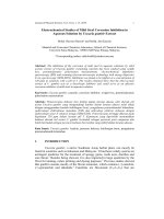
Figure 1 shows the layer of thin film sample of ITO/PT/CHLO that had
been prepared and used in this study.
Electrical Conductivity of Chlorophyll 80
2.1 Solution Preparation
PT is synthesized from chemical oxidation with the FeCl
3
as catalyst in
chloroform in the absence of surfactants.
4
Then, the PT was diluted in 50 ml of
acetonitril. CHLO was extracted from seaweed.
5
In this study, CHLO used was in
chemical compound called pophyrine. It was diluted from the slide into 50 ml
chloroform which results in 1.084 g of slide and CHLO. Then, the cleaned slide
was weighted again to determine the weight of the CHLO contained in the 25 ml
chloroform. Thus, 0.001 g of CHLO was known. The mean of the CHLO
concentration is 4 x 10
–5
g cm
–1
.
2.2 Preparation of ITO Substrate
The ITO which is used as working electrode was firstly cleaned with
distilled water for 10 min, followed by detergent for 10 min, then with distilled
water again for 10 min. Lastly, it was cleaned with acetone for 10 min before
cleaned with the distilled water for 10 min. After that, it was dried using the hair
dryer before kept into a Petri dish.
2.3 Preparation of Thin Film
The thin films were prepared by using different techniques for each layer.
First layer that had been deposited on the ITO substrate is the PT thin film by
using electrochemistry method and the second layer is CHLO thin film which had
been deposited on the PT thin film layer using spin coating method.
2.4 Electrodeposition of PT by Electrochemistry Method
PT thin film was be deposited by electrochemistry method using the
Electrochemical Impedance Spectroscopy (EIS) PGSTAT302. A typical
electrochemical impedance experimental set-up consists of an electrochemical
CHLO
PT
ITO
Glass substrate
Figure 1: The layer of thin film sample of ITO/PT/CHLO p-n heterojunction solar cell.
Journal of Physical Science, Vol. 19(2), 77–92, 2008 81
cell (the system under investigation), a potentiostat/galvanostat and a General
Purpose Electrochemical System (GPES).
This instrument consists of three electrodes. A three-electrode
configuration for an electrochemical cell is the most common for typical
electrochemical applications. The first of these electrodes is the working
electrode. The thin film was deposited on this electrode. The second functional
electrode is the counter electrode, which serves as a source sink for electrons so
that the current can be passed from the external circuit through the cell. The third
is the reference electrode, in which the potential is constant enough and can be
taken as the reference standard. The electrode is used to determine the potential
of the working electrode precisely. Since the absolute potential of a single
electrode cannot be measured, all potential measurements in electrochemical
systems are performed with respect to a reference electrode. A reference
electrode, therefore, should be reversible, and its potential should remain constant
during the course of the measurement.
This technique was used just to provide electrodeposition of PT. By
using the GPES method software, Cyclic Voltanmetry (Staircase) method was set
to be in normal procedure. The procedure was set to be as in Table 1. The cyclic
of the process was set at the ‘Measurement’ column for 5, 10, 15, 20 and 25
cyclic or also known as scan. Each sample was prepared for nine duplicates. The
number of cyclic determined the different of thicknesses.
2.5 Deposition of CHLO by Spin Coating Technique
CHLO thin film was be prepared using spin coating technique. In this
study, Spin Coater Model WS-400B-6NPP-LITE was used. Spin coating is a
procedure used to apply uniform thin films to flat substrates. In short, an excess
amount of the solvent is placed on the substrate, which is then rotated at high
speed in order to spread the fluid by centrifugal force. A machine used for spin
coating is called a spin coater, or simply spinner. Rotation is continued while the
fluid spins off the edges of the substrate, until the desired thickness of the film is
achieved. The applied solvent is usually volatile and simultaneously evaporates
(in this case, chloroform was used). So, the higher the angular speed of spinning,
Table 1: Procedure set for electrodeposition process of PT
Start Potential (V) –2.25
First Vertex Potential (V) –2.25
Second Vertex Potential (V) 2
Step Potential (V) 0.01007
Scan Rate (Vs
–1
) 0.050005
Electrical Conductivity of Chlorophyll 82
the thinner the film will be. The thickness of the film also depends on the
concentration of the solution and the solvent.
After a substrate was loaded on to the chuck, vacuum hold-down is
engaged from the side mounted control panel with the lid closed, and a pre-
programed process was selected and then initiated by only a few keystrokes.
CHLO was deposited on ITO/PT thin film using spin coating with 4 stages of
spin; 500 rpm for 10 s, 1000 rpm for 15 s, 1500 rpm for 20 s and 2000 rpm for
30 s to complete one cycle and then repeated the same way to finish with 5
cycles, 7 cycles and 10 cycles for each sample of 5, 10, 15, 20 and 25 cyclic of
PT thin films.
2.6 Electrical Conductivity Measurement of Thin Film
Electrical conductivity is the capacity of any object or substance to
conduct an electric current. When an electrical potential difference is placed
across a conductor, its movable charges flow, giving rise to an electric current.
The conductivity can be measured and has the SI units of siemens per meter
(Sm
–1
). The conductivity depends of the characteristics of the materials. A
conductor such as a metal has a high conductivity, and an isolator like glass,
wood and vacuum has a low conductivity. The conductivity of a semiconductor is
generally intermediate, but varies widely under different conditions.
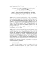
Four point probe is used to determine the conductivity of the thin film. In
this study, the sheet resistivity in produced films was measured with complete
four point probing system consists of the Jandel Universal Probe combined with a
Jandel RM3 Test Unit (Fig. 2). The two outer probes supply a voltage difference
that drives a current through the film. The two inner probes pick up a voltage
difference, and the sheet resistivity is calculated via a physical model of the
current distribution.
(a) (b)
Figure 2: The four point probes instrument consists of (a) Jandel Universal Probes and
(b) Jandel RM3 Test Unit as a control current and so on.
Journal of Physical Science, Vol. 19(2), 77–92, 2008 83
If an electric current is restricted to a 2D surface, the resistance of a
homogeneous rectangular conductor is “sheet resistivity multiplied by conductor
length divided by conductor width”. Because both of length and width have the
same unit (m), the SI unit of sheet resistivity and (real) resistance are the same –
ohms (). To avoid confusion, sheet resistivity is given in “ohms per square”
(/). In the measurements, sheet resistivities given by the instrument depended
strongly on the applied current through the sample. Electrical resistivity of the
thin film was measured. Sheet resistance (resistivity) for wafers and films are as
shown in Equation 1. The unit of sheet resistance is ohms per square (/):
R
S
= 4.532 x V / I (1)
Where, R
S
is the sheet resistance, 4.532 is the correction factor, V is the voltage
measured and I is the current applied from the test unit. Thus, electrical
conductivity can be determined which it is the reciprocal (inverse) of the
electrical resistivity, σ as shown in Equation 2. The unit of electrical conductivity
is ohm
–1
m
–1
(
–1
m
–1
) = Siemens m
–1
(Sm
–1
), where, σ is the electrical
conductivity and R
S
is the sheet resistivity.
σ = 1/R
S
(2)
2.7 Electrical Conductivity of Thin Film Under Different Intensity of
Light
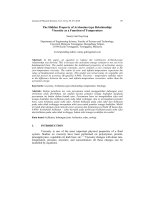
The electrical conductivity of the thin film with different thicknesses was
will measured in the dark and under the light by using the four point probes and
LI-200 Pyranometer Sensor [Fig. 3(a)]. The LI-200 Pyranometer is designed for
field measurement of global solar radiation in agricultural, meteorological and
solar energy studies. The LI-200 features a silicon photovoltaic detector mounted
in a fully cosine-corrected miniature head. Current output, which is directly
proportional to solar radiation, is calibrated against an Eppley Precision Spectral
Pyranometer (PSP) under natural daylight conditions in units of watts per square
meter (Wm
–2
). Under most conditions of natural daylight, the error is < 5%. The
LI-1400 [see Fig. 3(b)] is a multipurpose data logger that functions both as a data
logging device and a multichannel, autoranging meter. The LI-1400 electronics
are optimized to measure the current output of LI-COR radiation sensors, as well
as voltage sensors and sensors with a pulsed output. The chancing of electrical
conductivity with the different intensity of light on the ITO/PT/CHLO was
investigated in this work. The electrical conductivity of all samples of thin film
was measured under dark, 10, 20, 30, 40, 50, 60, 70, 80, 90 and 100 Wm
–2
.
Electrical Conductivity of Chlorophyll 84
(a) (b)
Figure 3: A set of intensity measurement using sensor. (a) LI-200 Pyranometer Sensor
and (b) LI-1400 Data Logger.
3. RESULTS AND DISCUSSION
3.1 Electrical Conductivity of PT/CHLO Thin Film Under Dark
Condition
Table 2 shows the electrical conductivity of PT/CHLO in the dark
condition; which graphs in Figures 4 and 5 were obtained from the values.
Electrical conductivity of PT/CHLO with different thicknesses of PT was
observed under dark condition and the results are shown in Figure 5. This figure
shows that the electrical conductivity of the PT/CHLO thin films increased with
the increasing of PT thickness. Combination of PT/CHLO 5 thin film could
conduct electricity better (compared to the combination of PT/CHLO 7 and
PT/CHLO 10 thin films) when combined with PT5, PT10 and PT15 thin films.
With thicker PT thin films, especially for PT20, it shows the highest electrical
conductivity of PT/CHLO thin film when combined with CHLO 10. It is differed
to PT25; which it shows the highest conductivity when it was combined with
CHLO 7 thin films.
Table 2: Electrical conductivity of PT/CHLO in the dark condition.
Electrical Conductivity, σ (Sm
–1
)
Sample CHLO 5 CHLO 7 CHLO 10
PT5 0.080 0.078
0.081
PT10 0.079 0.077
0.078
PT15 0.083 0.080
0.082
PT20 0.087 0.085
0.088
PT25 0.084 0.086
0.076
Journal of Physical Science, Vol. 19(2), 77–92, 2008 85
0.089
0.087
0.085
0.0.83
0.0.81
0.079
0.077
0.075
Electrical Conductivity, (Sm
–1
)
0 25 5 10 15 20
Thickness of PT
Figure 4: Electrical conductivity of PT/CHLO thin films at different thicknesses of PT.
CHLO 5; CHLO 7; CHLO 10.
Figure 5: Electrical conductivity of PT/CHLO thin films at different thicknesses of
CHLO. PT5; PT10; PT15; PT20;
PT25.
0.09
0.088
0.086
0.084
0.082
0.08
0.078
0.076
0.074
5 6 7 8 9 10
Thickness of CHLO
Electrical Conductivity, (Sm
–1
)
However, combination with PT25 thin film, shows an obvious declining
of electrical conductivity values. Indicate that the ITO/PT/CHLO thin films can
conduct electricity under the dark condition. In this case, it conclude that the
thickness of the CHLO thin film affects the performance of the ITO/PT/CHLO
thin film; which the ability of the thin film to conduct electricity could be better
with the thinner CHLO thin film.
Figure 5 shows the electrical conductivity with different CHLO thickness
which had been observed under the dark condition. The effect of CHLO thickness
on each PT thickness to the electrical conductivity was studied. In overall, it
Electrical Conductivity of Chlorophyll 86
showed that electrical conductivity of the PT thin films increase with the
increasing of the CHLO thin film thickness except for PT25 thin film; it
declining hastily. The figure indicates that PT20 gained the highest electrical
conductivity which it reaches 0.088 Sm
–1
. However, the increasing of the
electrical conductivity of PT20 to the CHLO thickness is inarticulately (the
difference between the highest and lowest value of electrical conductivity is only
3%). From here, it concludes that, the thicker the PT thin film, the higher the
electrical conductivity. However, the thickness of the PT thin film should not be
too thick because thick film acts as an insulator.
3.2 Electrical Conductivity of PT/CHLO Thin Film with Different
CHLO Thickness
Figure 6 shows the graph of electrical conductivity of PT5/CHLO
(PT5/CHLO 5, PT5/CHLO 7 and PT5/CHLO 10) thin films under different
intensity of light. Here, the effect of intensity of light to the PT5/CHLO thin film
was studied.
The graph showed that the thickness of PT5/CHLO 5, PT5/CHLO 7 and
PT5/CHLO 10 thin films increased with the increasing of intensity of light. It
means that the PT5/CHLO 5, PT5/CHLO 7 and PT5/CHLO 10 thin films are
suitable to make as solar cells due to their ability to change the light energy to
electrical energy.
The electrical conductivity of PT5/CHLO 10 thin film simultaneously
increased with the increasing of the intensity of light; which had been observed
until 100 Wm
–2
. PT5/CHLO 10 thin film also has the highest electrical
conductivity in a low intensity of light. For the PT5/CHLO 5 thin film, the
Figure 6: Electrical conductivity of PT5/CHLO thin films under illumination
with different thicknesses of CHLO thin films. CHLO 5; . CHLO 7;
CHLO 10.
0.07
0.075
0.08
0.085
0.09
0.095
Intensity of Tungsten Light (W m
–2
)
0.105
0.11
Electrical Conductivity, (Sm
–1
)
0.1
Journal of Physical Science, Vol. 19(2), 77–92, 2008 87
polynomial curve is obtained. The PT5/CHLO 5 thin film is energetically
increased from a low electrical conductivity at 10 Wm
–2
to the highest electrical
conductivity at 70–80 Wm
–2
(compared to the PT5/CHLO 7 and PT5/CHLO 10
thin films), but declining after that. PT5/CHLO 5 has a greater ability to changes
the light energy to the electrical energy compared to the PT5/CHLO 7 and PT
5/CHLO 10 thin films. For the PT 5/CHLO thin film, the combination of PT5
with CHLO 7 has the lowest ability to conduct electricity. The CHLO thin film
with 7 thickness did not really help in the improvement in the conductivity of
electron transfer path. From the results acquired, it can be concluded that CHLO
10/PT5 thin film is the most suitable to make as solar cell because it shows a
stable (increase consistently with the change of light intensity) and achieves a
high value of electrical conductivity reach up to ± 0.1 Sm
–1
(raise 22% compared
to the electrical conductivity in the dark condition).
Electrical conductivity of PT 10/CHLO (PT10/CHLO 5, PT10/CHLO 7
and PT10/CHLO 10) thin films under different intensity of light is shown in
Figure 7. Firstly, at 10 Wm
–2
, PT10/CHLO 5 thin film shows the electrical
conductivity attain a high values even higher than PT10/CHLO 7 and PT
10/CHLO 10 thin films. But it declines severely with the increasing of intensity
of light after 10 Wm
–2
. It means that the PT10/CHLO 5 is not suitable to make as
a solar cell. For the PT10/CHLO 7, electrical conductivity is increased at the
range 10–30 Wm
–2
but decreased slowly after that. It shows that the CHLO 7 is
not effectively helps to convert light energy to the electrical energy. However, the
electrical conductivity of the PT10/CHLO 7 thin film is the highest among the PT
10/CHLO 5 and PT5/CHLO 10 thin films. Gradually, PT10/CHLO 10 thin film
increase until 60 Wm
–2
then declining after that. The CHLO 10 thin film did help
improving the electron transfer path to the PT10. Therefore, the best PT10 thin
film to make as solar cell is the one that combined with CHLO 10 thin film.
Figure 8 shows the electrical conductivity of PT15/CHLO (PT15/CHLO
5, PT15/CHLO 7 and PT15/CHLO 10) thin films under different intensity of
light. All the thin films increased with the increasing of intensity of light. Thus, it
is suitable to make as a solar cell. Indicate that PT15/CHLO 5 shows the highest
electrical conductivity at 40–50 Wm
–2
which the value reaches 0.097 Sm
–1
(raising up 11% from the electrical conductivity that obtained under dark
condition). However, the electrical conductivity is then hastily declining when
exposed to the higher intensity of light. CHLO 5 did aid in improving the
conductivity of the electron transfer path. The electrical conductivity of PT
15/CHLO 7 did not suffer any change until 60 Wm
–2
; declining after that. For
PT15/CHLO 10 thin film, it increased slowly when the intensity of light is
Electrical Conductivity of Chlorophyll 88
0.06
0.065
0.07
0.075
0.08
0.085
0.09
5 15 25 35 45 55 65
Electrical Conductivity, , (Sm
–1
)
75 85 95 105
Intensity of Tungsten Light (Wm
–2
)
Figure 7: Electrical conductivity of PT5/CHLO thin films under illumination. PT10
with different thicknesses of CHLO thin films. CHLO 5 CHLO 7,
CHLO 10.
increased. The CHLO 7 thin film was not suitable because it was thick. For
CHLO 10 thin film, even though it was thicker than the CHLO 7 thin film, it still
can compete with geminate recombination because the thin film interface
separates excitons is more efficient. It is concluded that PT15/CHLO 5 thin film
is the most suitable to perform as solar cell compared to the PT15/CHLO 7 and
PT15/CHLO 10 thin films.
Figure 9 shows the electrical conductivity of PT20/CHLO (PT20/CHLO
5, PT20/CHLO 7 and PT20/CHLO 10) thin films. PT20/CHLO 5 thin film
decreases with the increasing of intensity of light although at the 10 Wm
–2
it
Figure 8: Electrical conductivity of PT15/CHLO thin films under illumination
with different thicknesses of CHLO thin films. CHLO 5; CHLO
7; CHLO 10.
0.06
0.05
0.07
0.075
0.08
0.085
0.09
0
10 20 30 40 50 60 70 80 90 100
Intensity of Tungsten Light (Wm
–2
)
Electrical Conductivity, (Sm
–1
)
Journal of Physical Science, Vol. 19(2), 77–92, 2008 89
shows the highest electrical conductivity compared to PT20/CHLO 7 and PT
20/CHLO 10. This is due to the charge separation of PT20/CHLO 5 thin film can
not compete successfully with the geminate recombination after a photon
absorption event. So, this combination of film thickness is not suitable to make as
solar cell because it cannot change light energy to electrical energy. Electrical
conductivity of PT20/CHLO 10 thin film increased with the increasing of light at
10–50 Wm
–2
but declining after 50 Wm
–2
. It also indicates the highest electrical
conductivity compared to the PT20/CHLO 5 and PT20/CHLO 7 thin films. It
means that the PT20/CHLO 10 thin film has an efficient photocurrent generation,
which the charge separation can compete successfully with the geminate
recombination after a photon absorption event especially at 40 Wm
–2
. From here,
a conclusion can be made; the PT20/CHLO 10 thin film is more suitable to
perform as a solar cell than PT20/CHLO 5 and PT20/CHLO 7 thin films.
The electrical conductivity of PT25/CHLO (PT25/CHLO 5, PT
25/CHLO 7 and PT25/CHLO 10) thin films under different intensity of light is
shown in Figure 10. At 10 Wm
–2
, PT25/CHLO 5 thin film shows the highest
electrical conductivity compared to PT25/CHLO 7 and PT25/CHLO 10 thin
films. But, indicate that it is declining simultaneously with the increasing of
intensity of light. Therefore, the PT25/CHLO 5 thin films is not suitable to make
as a solar cell because the combination of CHLO thin film with 5 thickness and
PT thin film with 25 thickness unable to improve the conductivity of electron
transfer path, due to the charge separation cannot compete with geminate
Figure 9: Electrical conductivity of PT20/CHLO thin films under illumination with
different thicknesses of CHLO thin films. CHLO 5; CHLO 7;
CHLO 10.
Electrical Conductivity, (Sm
–1
)
0.084
0.082
0.08
0.078
0.076
0.074
0.072
0.07
0 10 20 30 40 50 60 70 80 90 100
Intensity of Tungsten Light (Wm
–2
)
Electrical Conductivity of Chlorophyll 90
0.075
0.076
0.077
0.078
0.079
0.08
0 102030405060708090100
Intensity of Tungsten Light (Wm
−2
)
Electrical Conductivity, , S/m
Figure 10: Electrical conductivity of PT25/CHLO thin films under illumination with
different thicknesses of CHLO thin films. CHLO 5; CHLO 7;
CHLO 10.
Electrical Conductivity, (Sm
–1
)
0.08
0.079
0.078
0.077
0.076
0.075
0 10 20 30 40 50 60 70 80 90 100
Intensity of Tungsten Light (Wm
–2
)
recombination. For PT25/CHLO 7 and PT25/CHLO 10 thin films, they increased
slowly until reach to 30–40 Wm
–2
and decrease with the increasing of intensity of
light after 40 Wm
–2
. Firstly, at 10 Wm
–2
, PT25/CHLO 7 thin film shows the
lowest electrical conductivity among the other two thin films (PT25/CHLO 5 and
PT25/CHLO 7) but after 60 Wm
–2
, it indicates the highest electrical conductivity.
In overall, the ability of the PT25/CHLO 5 thin film to conduct electricity is poor
because PT25 is too thick.
4. CONCLUSION
The preparation of PT thin films using electrochemistry method is
successfully done with the different thicknesses. The deposition of different
thicknesses of CHLO thin films on the PT thin films is also successfully done by
spin coating technique.
The electrical conductivity in dark condition was increased with the
increasing of PT thin film thickness. While, with the increasing of CHLO thin
film thickness, electrical conductivity in the dark is consecutively change. Under
dark condition where no absorption of light occurs, the thickness of the CHLO
thin film affects the performance of the ITO/PT/CHLO thin film; which the
ability of the thin film to conduct electricity could be better with the combination
of thinner CHLO thin film and thicker PT thin film. At this condition, CHLO acts
as an insulator while PT is a conductive polymer.
Journal of Physical Science, Vol. 19(2), 77–92, 2008 91
The electrical conductivity of the PT/CHLO thin films was increasing
with the increasing of intensity of light from 10–100 Wm
–2
. The results showed
that as the thicker CHLO thin film combined with thinner PT thin film, the higher
electrical conductivity can be gained. This study, the combination of CHLO 10
thin film (the thickest CHLO thin film) and PT 5 thin film (the thinnest PT thin
film) achieved the highest electrical conductivity reach up to ± 0.1 Sm
–1
(raise
22% compared to the electrical conductivity in the dark condition). Therefore, the
ITO/PT5/CHLO 10 is the most suitable to perform as p-n heterojunction solar
cell.
5. REFERENCES
1. Heeger, A.J. (2001). Semiconducting and metallic polymers: The fourth
generation of polymeric materials. J. Phy. Chem. B, 105, 8475–8491.
2. Wallace, G.G., Dastoor, P.C., Officer, D.L. & Too, C.O. (2000).
Conjugated polymers: New materials for photovoltaics. Chem. Innov.,
30, 14–22.
3. Brabec, C.J., Sariciftci, N.S. & Hummelen, J.C. (2001). Plastic solar
cells. Journal of Advance Function Materials, 11, 15–26.
4. Kim, G.B. (2005). B. Sc. In Chemical Science, Kolej Universiti Sains
dan Teknologi Malaysia.
5. Syed Hafidz, S.A.R. (2006). Penyediaan dan pencirian filem nipis
klorofil. Laporan Ilmiah Tahun Kepujian, Kolej Universiti Sains dan
Teknologi Malaysia, Terengganu.
6. Akiyama, T., Kakutani, K. & Yamada, S. (2004). Fabrication and
photoelectrochemical properties of polythiophene-porphyrin composite
films. Jpn. J. Appl. Phys., 43, 2306.
7. Akiyama, T., Matsushita, M., Kakutani, K., Yamada, S., Takechi, K.,
Shiga, T., Motohiro, T., Nakayama, H. & Kohama, K. (2004). Solid-state
solar cells consisting of polythiophene-porphyrin composite films. Jpn. J.
Appl. Phys., 44, 2799.
8. Chan, H.S.O. & Ng, S.C. (1998). Synthesis, characterization and
applications of thiophene-based functional polymers. Prog. Polym. Sci.,
23, 1167–1231.
9. Cartlidge, E. (2007). Bright outlook for solar cell. Physics World.
10. Eugeny, A.E., Sebastian, T., Thomas, W., Michael, T.M.C, Dennis, K.P.
& Beate, R. (2006). Photoinduced electron and energy transfer in a new
porphyrin-phthalocyanine triad. Chem. Phys., 328(1–3), 428–437.
11. Gherghel, M. (2005). On the optoelectronic information transfer
phenomenon at the intelligent interfaces of some mixed multilayer (Bio)
structure. J. Optoelectron. Adv. M., 7(6), 2881–2886.
Electrical Conductivity of Chlorophyll 92
12. Goetzberger, A., Hebling, C. & Schock, H.W. (2003). Photovoltaic
materials, history, status and outlook. Mater. Sci. Eng., 40, 1.
13. Halls, J.J.M. & Friend, R.H. (2001). Organic photovoltaic devices. In
M.D. Archer & R.D. Hill, (Eds.). Clean electricity from photovoltaics.
London: Imperial College Press, 377–445.
14. Hiramoto, M., Fukusumi, H. & Yokoyama, M. (1992). Organic solar
cell based on multistep charge separation system. Appl. Phys. Lett., 61,
2580.
15. Hoppe, H. & Sariciftci, N.S. (2004). Organic solar cells: An overview.