Báo cáo vật lý: "MODELLING AND SIMULATION STUDY OF VISIBLE EMISSION TRANSMISSIVITY OF SILICON RELATED TO SINGLE AND MULTILAYER ANTIREFLECTION COATINGS" potx
Bạn đang xem bản rút gọn của tài liệu. Xem và tải ngay bản đầy đủ của tài liệu tại đây (490.25 KB, 12 trang )
Journal of Physical Science, Vol. 17(2), 15–26, 2006 15
MODELLING AND SIMULATION STUDY OF VISIBLE
EMISSION TRANSMISSIVITY OF SILICON RELATED TO
SINGLE AND MULTILAYER ANTIREFLECTION COATINGS
Kifah Q. Salih and M.R. Hashim*
Solid State and Applied Physics Group, School of Physics,
Universiti Sains Malaysia, 11800 USM Pulau Pinang, Malaysia
*Corresponding author:
Abstract: In this study, the effect of single and multilayer thin film coatings at the
central wavelength 720 nm on the transmissivity of silicon as active medium has been
investigated. A model, based on the Transfer Matrix Method (TMM) of multilayer is used
to evaluate the transmittance of Si as active medium (emitter) at 720–750 nm when Ge,
SiO
2
and Si are used as single and multilayer thin film coatings. The results of this
simulation study lead to the following conclusions: the transmissivity of ~ 720–750 nm
emission of silicon is affected significantly by the single and multilayer thin film coatings
of Ge, SiO
2
and Si/SiO
2
/air and Si/Ge/Si/SiO
2
/air show high transmissivity of 92% and
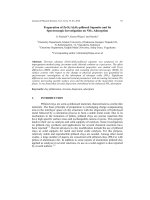
100% at 720 nm respectively. Uncoated Si (active medium) surface shows low
transmissivity of 66%. The width of the high-transmittance region of Si/Ge/Si/SiO
2
/air is
less than Si/SiO
2
/air at 720 nm.
Keywords: antireflection coatings, silicon active medium, transmissivity
1. INTRODUCTION
Crystalline Silicon (c-Si) is an indirect semiconductor and has little
efficiency in light emission. However, the optical properties of porous Si (p-Si)
are significantly different from those of bulk c-Si. p-Si is actually a
nanocrystalline material. It has dimensions in the low nanometer range.
Canham [1] reported that if the structure size reaches a value on the order of
< 5 nm, quantum effects can occur and in fact these effects cause the strong
visible PL in the region 1.4–2.2 eV. Nanocrystallite Si has been studied
extensively because it would open a new possibility for indirect-gap semi-
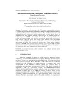
conductors as new materials for optoelectronic applications. The transmissivity of
Si emission at the air-silicon is low due to the large refractive index discontinuity
that exists at the air-silicon range [Fig. 1(a)]. By placing a single layer of
antireflective coating (AR) of intermediate refractive index on the silicon surface,
this large index discontinuity is broken into two smaller steps [Fig. 1(b)],
resulting in a lower broadband reflectivity. Further reduction in broadband
reflectivity can be achieved by
adding additional intermediate index layers, thus
Modelling and Simulation Study of Visible Emission 16
breaking the air-silicon index discontinuity into smaller and smaller steps.
Therefore, a gradient index AR is the limit of this progression, where a single
index discontinuity is replaced by a continuous transition from high to low index
material (air) as shown in Figure 1(c). If this continuous index transition occurs
over several wavelengths of optical path length, broadband reflectivity
approaching zero can be achieved [2].
Refractive Index
Refractive Index
Distance from surface (×)
(a)
Distance from surface (×)
(b)
Refractive Index
Refractive Index
Distance from surface (×)
(c)
Distance from surface (×)
(d)
Figure 1: Four basic spatial refractive index profiles of thickness d:
(a) No AR film, (b) single layer AR film, (c) linear
graded AR film, and (d) AR film with a partial gradient
(n
x
is arbitrary)
Graded refractive index profile i.e., n = n (λ, d), where d is the depth
from the surface, offers the best performance. Different kind of paraboloid or
exponential refractive index profiles can give very broad transmission bands.
Single-layer antireflections coatings are generally deposited with a thickness of
λ/4, where λ is the desired wavelength for peak performance. Since the refractive
index of air is 1.0, the thin antireflection film ideally should have a refractive
index of
substrate
n [3–5]. There is no ideal material that can be deposited in
durable thin layers with a low enough refractive index to satisfy this requirement
exactly [3]. These coatings are still more theoretical than practical solution
because refractive index gradients are difficult to control during fabrication. In
this paper, we explain the model and basic formula of single and multilayer
Journal of Physical Science, Vol. 17(2), 15–26, 2006 17
antireflection coatings of Si, SiO
2
and Ge for increasing transmittance of Si as
active medium in the far red region of 720–750 nm. This paper reports the design
and
simulation of the transmissivity of single and multilayer coatings; and also
reports the results of each design at the central wavelength 720 nm.
2. MODELING AND SIMULATION
The knowledge of thickness and refractive index of AR coatings on
semiconductor material surface is a key issue for increasing the performance
efficiency of emitters such as output intensity, monochromaticity. Single and
multilayer antireflection coatings are designed to increase material surface
transmission and reduce surface reflection over a specific wavelength range. The
transmittance curves can be calculated with the transfer matrix method for as
many AR layers as desired using MATLAB software. In the case of silicon as
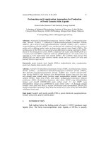
emitter, the radiation are emitted in all directions. The main loss mechanism of
emitter in the material is due to defects, surface roughness and emitter-air
interface properties (contacts and the reflectivity). This latter loss is very
significant as silicon has relatively high refractive index as shown in Figure 2.
≈
Figure 2: A schematic illustrating the main optical losses
mechanism of emission light at Si/air interface
Of the radiation emitted in the forward direction, that striking the front surface at
an angle
θ
> sin
–1
(1/n) will suffer total internal reflection I
RT
. Hence, emitted
radiation in a cone of half-angle less than this value will be capable of being
emitted, that is I/2n
2
of the radiation emitted (I
E
) in the forward half-sphere. This
radiation will suffer partial reflection (I
R
), given for near normal incidence by
Fresnel’s law as [6–8]:
Modelling and Simulation Study of Visible Emission 18
2
1
1
R
E
I
n
In
−
⎛⎞
=
⎜
+
⎝⎠
⎟
(1)
In our optical model for increasing the transmissivity of visible emission
of Si related to Figure 2, the contribution of the single and multilayer
antireflection coatings are calculated using the transfer matrix method at the
central wavelength 720 nm (where incident angle of emitted light at Si/air
interface is
θ
= 0). In the calculation, we use theoretically determined optical
thickness (d) of all materials with n
Si
= 3.76, n
SiO
2
= 1.455, n
Ge
= 4.897. Single-
layer AR coatings are generally deposited with a thickness of
λ
4, where
λ
is the
desired wavelength for peak performance; in our study
λ
is 720 nm.
In the study, we propose Si as a simple rectangular diode geometry in the
far red region of 720–750 nm which is so easily fabricated by scribing and
cleaving with this wavelength design, so we can explain our modeling using
Figure 2 at Si/air interface only or Si surface-AR coatings interface (single or
multilayer). A plain wave (emission wave from Si) interacting with a stack of
thin layers is considered, so [9,10]:
E = E e H = H e (2)
0
ikr–iωt
0
ikr–iωt
Where E and H are the electrical field and the magnetic field strengths,
respectively, E
0
and H
0
are their amplitudes, k is a wave vector and ω is the
frequency of the incident light. We let the thin layers to have different refractive
indices.
Inside each layer, the related Maxwell’s equations are [9,10]:
k × E
0
= (– ω/c) × H
o
k × H
0
= (–ωn
2
/c) × H
0
(3)
The boundary conditions at the interface of two layers having different refractive
indexes n
1
and n
2
are:
(E
0
)
т1
= (E
0
)
т1
n
1
(e
k
× E
0
)
т1
= n
2
(e
k
× E
0
)
т2
(4)
Where the subscript т denotes the tangential component with respect to the
boundary and e
k
shows the direction of the wave propagation. For simplicity, we
consider normal incidence of light with plane polarization (θ = 0). So, N layers of
n
j
can be expressed in terms of the field (E) [9–10]:
Journal of Physical Science, Vol. 17(2), 15–26, 2006 19
1
121
ˆˆ
ˆˆ ˆ ˆ
( )
−
−−
+
⎛⎞ ⎛⎞
=
⎜⎟ ⎜⎟
−−
⎝⎠ ⎝⎠
aNNn a
f
inal initial
E+ E
SBBB BS
EE
(5)
Where the subscript a is related to the environmental area, are the surface
matrices:
ˆ
S
Ŝ
j
= (6)
⎟
⎠
⎞
⎜
⎝
⎛
−
jj
nn
11
Where,
ˆ
B
is the layers' matrices:
1
sin
cos
ˆˆ
ˆˆ
()
sin cos
j
j
j
jjjj
jj j
j
ji
n
B=SΦ S=
in j j
−
⎛⎞
⎜⎟
⎜⎟
⎜⎟
⎝⎠
(7)
Where Ф is the diagonal phase matrix connecting the fields E
j
(z) at the opposite
surfaces of the layer j, φ
j
is equal [9,10]:
jj j
nd
c
ϕ
ω
=
j
n
(8)
Where d
j
is the layer thickness and k
j
= n
j
ω/c is the wave number of the j-th layer.
Each layer is considered separately. Thus, the transmission can be expressed in
term of field E [9]:
2
2
()
()
f
i
E
Tt
E
+
+
=
=
(9)
Equation (9) can be expressed as [10]:
C
Y
B
=
(10)
Where Y is the optical admittance and B and C are the total magnetic and total
electric amplitude of the light propagation in the medium, respectively. So, the
transmittance (T) can be explained in term of Y as below:
()
()()
osub
oo
4Y Re Y
T
YB C YB C
=
++
(11)
Modelling and Simulation Study of Visible Emission 20
3. RESULTS AND DISCUSSION
The transmissivity curves in the far red region 720–750 nm of
electromagnetic spectrum for antireflection coatings of Si/air, Si/Ge/air,
Si/SiO
2
/air, Si/Ge/SiO
2
/air, Si/SiO
2
/Ge/air, Si/Ge/Si/air, Si/Ge/Si/Ge/air, Si/Ge/
Si/SiO
2
/air and Si/SiO
2
/Si/SiO
2
/air AR coating structures as single layer and
multilayer thin film coatings have been simulated and plotted in Figures 3–12.
Please note that the maximum transmittance is obtained from Figure 11 of
Si/Ge/Si/SiO
2
/air.
400 600 800 1000 1200 1400 1600 1800
0.6638
0.6638
0.6638
0.6638
0.6638
0.6638
0.6638
0.6638
0.6638
0.6638
Wavelength vs Transmissivity
Transmissivity (%)
wavelength nm
Si(active medium)/Air
Transmissviity (%)
Figure 3: Simulated transmissivity for Si/air at λ = 720 nm:
n
Si
= 3.76, n
air
=1.0 (i.e., uncoated Si surface)
400 600 800 1000 1200 1400 1600 1800
0.74
0.76
0.78
0.8
0.82
0.84
0.86
0.88
0.9
0.92
0.94
Wavelength vs Transmissivity
Tran smissivity (%)
wavelength nm
Si(active medium)/SiO2/Air
Transmissivity (%)
Figure 4: Simulated transmissivity for Si/SiO
2
/air. SiO
2
layer is λ/4 thick at λ = 720 nm: n
SiO
2
= 1.455
Journal of Physical Science, Vol. 17(2), 15–26, 2006 21
400 600 800 1000 1200 1400 1600 1800
0.46
0.48
0.5
0.52
0.54
0.56
0.58
0.6
0.62
Wavelength vs Transmissivity
Tr ansmissivity (%)
wavelength nm
Si(active medium)/Ge/Air
Transmissivity (%)
Figure 5: Simulated transmissivity for Si/Ge/air. Ge layer
is
λ
4 thick at
λ
= 720 nm: n
Ge
= n
H
= 4.897
400 600 800 1000 1200 1400 1600 1800
0
0.1
0.2
0.3
0.4
0.5
0.6
0.7
Wavelength vs Transmissivity
Transmissivity (%)
wavelength nm
Si(active medium)/SiO2/Ge/Air
Transmissivity (%)
Figure 6: Simulated transmissivity for Si/SiO
2
/Ge/air. Layers are
λ/4 thick at λ = 720 nm: n
Si
= 3.76, n
SiO
2
= 1.455,
n
Ge
= n
H
= 4.897
Modelling and Simulation Study of Visible Emission 22
400 600 800 1000 1200 1400 1600 1800
0.62
0.64
0.66
0.68
0.7
0.72
0.74
0.76
Wavelength vs Transmissivity
Transmissivity (%)
wavelength nm
Si(active medium)/Ge/SiO2/Air
Transmissivity (%)
Figure 7: Simulated transmissivity for Si/Ge/SiO
2
/air. Layers are λ/4
thick at λ = 720 nm: n
Si
= 3.76, n
H
= 4.897, n
L
= 1.455
400 600 800 1000 1200 1400 1600 1800
0.5
0.55
0.6
0.65
0.7
0.75
0.8
0.85
0.9
Wavelength vs Transmissivity
Transmissivity (%)
wavelength nm
Si(active medium)/Ge/Si/Air
Transmissivity (%)
Figure 8: Simulated transmissivity for Si/Ge/Si/air. Layers are λ/4
thick at λ = 720 nm: n
Si
= 3.76, n
H
= 4.897, n
Si
= 3.76
Journal of Physical Science, Vol. 17(2), 15–26, 2006 23
400 500 600 700 800 900 1000 1100
0.3
0.35
0.4
0.45
0.5
0.55
0.6
0.65
0.7
0.75
0.8
Transmissivity vs Wavelength
Wavelength (nm)
Transmissivity (%)
Si(active medium)/Ge/Si/Ge
Transmissivity (%)
Figure 9: Simulated transmissivity for Si/Ge/Si/Ger/air. Layers are
λ/4 thick at λ = 720 nm: n
Si
= 3.76, n
H
= 4.897, n
Si
= 3.76
400 500 600 700 800 900 1000 1100
0.3
0.35
0.4
0.45
0.5
0.55
0.6
0.65
0.7
0.75
Transmissivity vs Wavelength
Wavelength (nm)
Tr a ns missivity (%)
Si(active medium)/SiO2/Si/SiO2/Air
Transmissivity (%)
Figure 10: Simulated transmissivity for Si/SiO
2
/Si/SiO
2
/air. Layers
are λ/4 thick at λ = 720 nm: n
Si
= 3.76, n
L
= 1.455
Modelling and Simulation Study of Visible Emission 24
400 500 600 700 800 900 1000 1100
0.65
0.7
0.75
0.8
0.85
0.9
0.95
1
Transmissivity vs Wavelength
Wavelength (nm)
Transmissivity (%)
Si(active medium)/Ge/Si/SiO2/Air
Transmissivity (%)
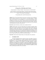
Figure 11: Simulated transmissivity for Si/Ge/Si/SiO
2
/air. Layers
are λ/4 thick at λ = 720 nm: n
H
= 4.897, n
Si
= 3.76
In the curves of Figures 4, 7 and 8, the width of the high-transmissivity
region decreases while its height increases, due to the refractive index difference
(∆n) between AR coatings materials. The difference between the curves of
Figure 4 and Figure 11 is caused by the refractive index difference at interfaces
as illustrated in regions 1(c) and 1(d) and region 2(b) of Figure 12.
Figure 12: A schematic diagram illustrating the graded refractive
index profile of Si/Ge/Si/SiO
2
/air and Si/SiO
2
/air
antireflection coating structure
Journal of Physical Science, Vol. 17(2), 15–26, 2006 25
These curves show good transmissivity due to the refractive index
difference at interfaces, i.e., at SiO
2
-air interfaces [1(d) and 2(b), Fig. 12] as well
as due to the insertion of an extra Si layer between the periodic structures.
Figures 9–11 show blue transmissivity at about 440–490 nm. In particular, Figure
11 shows high blue transmissivity (~96%) at 480 nm because the rejection zone
(2∆g) is solely a function of the indices of the two materials used to construct the
multilayer in the case of a quarter wave stack with layers of refractive index n
L
and n
H
. So, we can expressed our results from the figures in term of the width of
the rejection zone (2∆g):
∆g = 2/
π
sin
–1
(n
H
– n
L
) / (n
H
+ n
L
), (12)
Figure 11 shows good result in such that: by reduction of rejection zone in the
total amount of material will reduce the losses due to residual absorption in the
materials and thus increase the transmittance.
4. CONCLUSION
In this paper, we presented the simulated transmissivity of Si as emitter
using the transfer matrix method. This method directly calculates the theoretical
optical transmissivity values of the far red emission of Si using only refractive
indices and thickness of coating materials from Si, SiO
2
and Ge. The maximum
transmissivity of Si in 720–750 nm region of the electromagnetic spectrum can
be obtained with insertion of an extra Si layer between the periodic structures of
alternately high and low index of Ge and SiO
2
as evident from Figure 11.
5. REFERENCES
1. Canham, L.T. (1990). Appl. Phys. Lett., 57, 1046–1048.
2. Jacobsson, R. (1997). In E. Wolf (Ed.). Progress in optics. Vol. 5. New
York: John Wiley & Sons, 249.
3. Coating theory. Single-Layer Antireflection Coatings. www.mellesgriot
.com/products/optics/oc_2_2.htm (accessed January 10, 2005).
4. Southwell, W.H. (1983). Optics Letters, 8, 584.
5. Berning, P.H. (1962). J. Opt. Soc. Am., 52, 231.
6. Heavens, O. (1970). Thin film physics. London: Methuen.
7. Glang, R. & Maissel, L.I. (1970). Handbook of thin film technology.
London: McGraw-Hill.
8. Jenkins, F.A. & White, H.E. (1976). The fundamentals of optics. London:
McGraw-Hill.
Modelling and Simulation Study of Visible Emission 26
9. Aroutiounian, V.M., Martirosyan, K.H. & Soukiassian, P. (2004).
J. Phys. D. Appl. Ohys., 37(19), L25–L28.
10. Aroutiounian, V.M., Maroutyan, K.R., Zatikyan, A.L. & Touryan, K.J.
(2002). Thin Solid Films, 517, 403–404.