Báo cáo lâm nghiệp: "Infrared images of heat fields around a linear heater in tree trunks: what can be learned about sap flow measuremen" pptx
Bạn đang xem bản rút gọn của tài liệu. Xem và tải ngay bản đầy đủ của tài liệu tại đây (663.42 KB, 8 trang )
Ann. For. Sci. 63 (2006) 653–660 653
c
INRA, EDP Sciences, 2006
DOI: 10.1051/forest:2006046
Original article
Infrared images of heat fi elds around a linear heater in tree trunks:
what can be learned about sap flow measurement?
Helmut T
a
*
, Nadezhda N
b
,JanC
b
a
Hahn-Meither Institute, Dept. Solare Energetik, 14109 Berlin, Germany
b
Institute of Forest Ecology, Mendel University of Agriculture and Forestry, Zemedelska 3, Brno 61300, Czech Republic
(Received 23 September 2005; accepted 22 February 2006)
Abstract – This contribution aims at improving the understanding of sap flow measurements in trees. Infrared heat field images taken around heating
needles in sap transporting tree trunks are characterized by isotherms of elliptic shape with the heating needle in the lower focus. Increasing sap
flow increases the eccentricity of the elliptic heat field. This dynamics of ellipses provides a simplified experimental-mathematical approach for the
understanding and evaluation of the otherwise very complicated heat transfer- and distribution-problem involved. The results obtained are used to
discuss criteria for possible improved positioning patterns for needle sensors aimed for sap flow calculation using the dynamics of ellipses.
ellipse / heat dissipation method / heat field deformation method / linear heater / sensor geometry
Résumé – Images infrarouges des champs de chaleur autour d’un radiateur linéaire dans les troncs des arbres : que peut-on apprendre au
sujet de la mesure du flux de sève ? Cet article vise à améliorer la compréhension des mesures du flux de sève dans les arbres. Des images infrarouges
prises autour des aiguilles de chauffage dans les troncs transportant la sève ont été caractérisées par des isothermes de forme elliptique avec l’aiguille
chauffante dans le foyer le plus bas. L’accroissement du flux de sève accroît l’excentricité du champ de chaleur elliptique. Ces dynamique des ellipses
fournissent une approche expérimentale et mathématique simplifiée pour la compréhension et l’évaluation autrement très compliquée du problème du
transfert de chaleur. Les résultats obtenus sont utilisés pour juger de l’exactitude de la dissipation de la chaleur (HD) et de la déformation du champ de
chaleur (HDF), des mesures techniques et discuter des critères pour une possible amélioration des modèles de positionnement des aiguilles détecteurs
visant à calculer le flux de sève en utilisant les dynamiques des ellipses.
méthode de la dissipation de la chaleur / méthode de la déformation du champ de chaleur / radiateur linéaire / géométrie du détecteur
1. INTRODUCTION
The behavior of water in living plants is a mayor challenge
for both biologists and physical chemists. A critical issue is the
collection of reliable experimental data. The transport of wa-
ter in trees via the cohesion tension mechanism has been dis-
cussed for more than one century, and it is supported by a lot of
modern evidence [10,20,23,24,28,30]. But there are conflict-
ing opinions [32] and an ongoing controversy [3]. Recently, a
molecular kinetic theory has been proposed for the dynamics
of cohesive (tensile) water turnover in trees [27]. It supports
the cohesion-tension mechanism by showing that energy con-
version via evaporative pulling of water is functioning. But it
also introduces a more in-depth understanding of this remark-
able mechanism: the build-up of cohesive tension is not simply
a side phenomenon of ordinary water evaporation from leaves.
It is not merely a process coupled to the water potential gradi-
ent, which develops between the atmospheres via the tree wa-
ter conduits to the roots. The kinetic model for tensile water
turnover [27] describes the water-tree system under solar irra-
diation as a vapor machine, which works subject to irreversible
* Corresponding author:
thermodynamics. It functions as a self organizing system and
its main properties can be mathematically derived from wa-
ter interactions which consider reasonable feedback interac-
tions via hydrogen bond dynamics between water molecules.
They include self-organization of water into tensile structure,
chaos (cavitation), oscillations (occasionally observed with the
sap of plants) and a bi-stable state of water evaporation from
the leaves. The latter was experimentally verified in [27] and
demonstrates that evaporation of water from leaf structures
does not follow the expectation of reversible thermodynamics,
where water and vapor are in equilibrium. Evolution has de-
signed the water conduit systems in such a way as to maintain
the included water as a non-equilibrium “micro-canonical” en-
semble. When water is pulled by evaporation processes and
an increasing concentration of hydrogen bonds is activated
(like in super-cooled water or in ice structures) autocatalysis
in bond formation occurs leading to self-organization.
In the controversy on the cohesion – tension mechanism
[3, 32] the reliability of tensile water measurement is an im-
portant issue. The new interpretation of tensile water dynam-
ics [27] attributes to sap transport a non-linear dynamics (soft
matter) behavior, which is quite different from that of ordinary
water. It will equally require reliable measurements for testing
Article published by EDP Sciences and available at or />654 H. Tributsch et al.
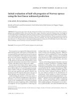
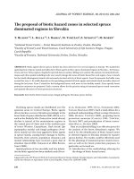
Figure 1. Experimental setup: Schemes and photo of the lime sample
tree stem prepared for taking infra-red images of heat field around a
linear heater visible in frontal direction: cross-section of the tree stem
with the radial sap flow sensor installed from the opposite side of stem
and the infra red camera focused on the smoothed stem surface. Dark
area in tree trunk limits zone with similar flow rates from both oppo-
site sides of stem (visible by infra-camera and measured between the
second and third outer thermocouples of the radial sensor).
and verification. Infrared imaging techniques have been used
in [27] to demonstrate via an additional experiment that water
is actually pulled by evaporation. It was also shown that in-
cident solar irradiation is intimately, but non-linearly, coupled
to sap transport. Water is directly pulled by evaporative solar
energy turnover.
In this publication it is attempted to show how infrared-
imaging techniques may help to better understand sap trans-
port dynamics in view of optimization and improvement of
traditional measurement techniques via heat sensors.
The application of thermal measurements for the analysis
of water transport in trees has a long history [1, 2, 4–9, 11].
They are based on a temporal or local thermal heating of sap
with different strategies for the detection of the displacement
of the heated liquid. Most interesting are techniques, which
allow long-term xylem sap flow measurements. Besides of
the heat-pulse velocity, HPV, technique, sap flow techniques
with continuous recording can be divided into essentially two
large groups: into methods applying the heated probe, HP, and
heat balance methods [4,6, 14, 21]. The first methods are sim-
pler but often give information on dynamics in relative units,
which have to be calibrated. The latter, being more compli-
cated, do not need calibration. The principles and comparative
properties of the main sap flow methods have been reviewed
[5,22,26]. Many types of heaters and of heat flow sensors have
been studied and applied but needle heaters [7, 12, 13, 17, 31]
have developed to special significance. Quite sophisticated
mathematical and numerical evaluations of the heat field dy-
namics have been provided [9, 15, 19, 25], but evidently more
information on the properties of heat fields in tree trunks is
required.
In most of the mentioned HP techniques the heated
and non-heated thermometers are applied (heat dissipation
method, HD, [7]), in the others two main arrangements of ther-
mocouples around the heater are used (heat field deformation
method, HFD, [17]). A symmetrical one with both ends placed
at equal distances up and down the heater along the axial di-
rection, and an asymmetrical one with the upper end of the
thermocouple placed at the same axial height as the heater
and a lower reference, placed at a certain distance below the
heater. The opinion has been expressed that symmetrical pairs
of thermocouples better “feel” the low fluxes, while asymmet-
rical ones “feel” the middle and high fluxes.
Application of infrared (IR) cameras allowed to get direct
images of the heat field comparable with sap flow rate [1,2,8].
Requirements to cut and smooth the stem surface seriously in-
jure a tree and it is the main drawback of such an approach for
a routine work. However, its goal is much better spatial reso-
lution and a possibility to get the general view of the heat field
when compared e.g. to the network of thermocouples installed
in the sapwood, which on the other hand can be more easily
recorded. Thus the IR technique is especially suitable e.g. for
relatively short-term testing of methods, while limited num-
ber of thermocouples can be applied for long-term studies in
almost intact trees.
In the present work, infrared thermal images of the dynam-
ics of heat field around a heating needle will be examined with
the expectation that characteristic properties can be identified,
which would allow improved strategies for simple in-situ mea-
surements.
2. MATERIAL AND METHODS
2.1. Sample tree
Lime sample tree (Tilia cordata Mill.) with diameter at breast
height (DBH) equal to 15.3 cm was prepared for frontal image of
heat field around the heater (Fig. 1). About 20 cm long outer part of
the stem was cut off down to the depth of 26 mm from the south-
ern side of stem and the opened xylem surface was smoothed by a
sharp knife. The IR-camera was focused on this accordingly prepared
stem surface. The radial HFD-sensor was installed from the opposite
(northern) side of the stem so that the end of the long linear heater
was visible on the smoothed surface and could generate the heat field
for IR-images. The depth of the heated point on the smoothed sur-
face corresponded to the xylem depth from the opposite side of the
stem situated between 4 and 5 thermocouples of the radial sensor.
Two small nails were fastened at the smooth surface 30 mm apart as
reference points.
2.2. Infra-red imaging
Infrared images were taken by the IR-camera (Model 600 IR
Imaging Radiometer from Inframetrics, 1990) with temperature res-
olution of 0.1
◦
C. The temperature scale was about 4
◦
C within the
range between 15 to 22
◦
C. The camera was mounted on a tripod
and focused on the stem of sample tree, so that the whole area of the
smooth stem surface was visible on the image.
Infrared images of heat field and sap flow 655
2.3. Sap flow measurements
Sap flow was measured by the heat field deformation method
[16, 17]. The sensor consisted of two pairs of stainless steel needles
1.2 mm in diameter, each containing six pairs of differential thermo-
couples, and a linear (needle-like) heater. One pair of such needles
was installed symmetrical at 15 mm distance above and below the
heater, the other one at 10 mm distance on the side of the heater. The
voltage from the thermocouples was measured and recorded every
minute by the multi-channel data-logger made by UNILOG (Brno,
Czechia). More detailed information about methods applied could be
found in recent publication [18].
3. RESULTS AND DISSCUSSION
3.1. Forms of heat field images
Under zero sap flow conditions an elliptic pattern of
isotherms was observed in the infrared image around the heat-
ing needle because heat conduction in axial direction is some-
what more favored compared to heat conduction perpendic-
ular to it. Without sap flow and the above-mentioned wood
anisotropy the ellipses should approach a circle. If they don’t
the ratio of the axes a/b will provide information on the asym-
metry of heat conduction parallel and perpendicular to the tree
axis.
Because the mathematical properties of ellipses will play a
mayor role in understanding heat fields, a few basic features
should be sketched here:
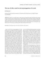
Ellipses follow mathematical laws explained in Figure 2:
They are described by two axes, a and b,twofoci,F1andF2,
the main limitations A and B, the side limitations C and D,
the centre M. Ellipses are characterized by the fact that any
point P on them satisfies the relation PF 1 + PF2 = 2a,thatis
the distance of focus F1 via point P to focus F2 is equivalent
to the dimension of the main axis 2a. The distance F1F2 = 2e,
that is twice the linear eccentricity e of the ellipse, described
by e =
√
a
2
− b
2
. The ratio of linear eccentricity to the big
axis, e/a, is called the numerical eccentricity ε. The segment
vertical to the main axis across the focus is called parameter p
with
p =
b
2
a
. (1)
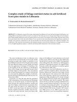
Figure 3 shows how the ellipses of iso-temperature profiles
change with increasing sap flow rate. While the sap flow in-
creases the heating source is “migrating” from the centre (zero
flow) to the lower focus of the ellipse (finite flow). The other
focus is shifting upwards, the more the higher the sap flow
rate. The reason is that the eccentricity of the ellipse is grow-
ing. At the same time the b-axis of the ellipse becomes smaller
satisfying the condition that the eccentricity e of the ellipses is
increasing while, to a first approximation, the area included by
an isotherm remains constant. Intuitively one can imagine that
the heat cannot progress so far away perpendicular to the sap
flow axis, because it is transported along with the sap.
Figure 2. (A) Mathematical representation of an ellipse in standard
(right part of an ellipse) and polar (left part of an ellipse) system of
coordinates: M, F1, F2 – center and foci of an ellipse; a, b and e –
main axes and eccentricity of an ellipse; rand ϕ polar coordinates of
an ellipse. (B) Mathematical law of an ellipse: the distance between
the two foci via any point on the ellipse is constant.
When the sap is transported along the x- axis the original
ellipse equation
x
2
a
2
+
y
2
b
2
= 1(2)
transforms into
(x −a
0
)
2
a
2
+
y
2
b
2
= 1, (3)
with a simultaneous change of its numerical eccentricity ε,
which is
ε =
√
a
2
− b
2
a
=
1 −
b
a
2
. (4)
This means: the ratio b/a (the ratio of small to big axis) is
changed due to the sap flow. As a consequence the centre of
the ellipse M shifts along the X axis (by a
0
), after the focus F1
has become identical with the heat source.
Figure 3 (drawing to the right) shows how a change of
sap flow rate and thus of eccentricity will influence the iso-
temperature profiles.
Intuitively the heat conduction process from the heat source
can be understood in the following way. Heat is spreading like
a wave in all directions and from every heated point heat may
spread again radially. Every point on the ellipse satisfies the
conditions that the distance between the two foci via this point
is constant. The heat needs the same time period to travel from
focus to focus of the ellipse via points on the ellipse itself
(Fig. 2B). If now the sap flow changes, the heat will be dis-
placed and the second focus shifts accordingly. This explains
the shift, with increasing sap flow, of the iso-temperature el-
lipses in Figure 3.
There are, of course, some complications, which will have
to be considered for obtaining more reliable information via
the ellipse dynamics. Ideally, the heat contained within the
sap filled area (which is abπ, the product of axes a and b,
multiplied by π bordered by an isotherm should be constant.
However, an elongated ellipse reflects through-flowing sap.
This sap has constantly to be heated up which may result in
656 H. Tributsch et al.
a somewhat contracted isotherm ellipse depending on the rate
of sap flow. There are additional complications: When care-
fully looking at the thermograms (Fig. 3B) one realizes that the
ellipses, even though their shapes are very regular, show one
peculiarity. The distance between the isothermal profiles be-
comes bigger around the focus which is more distant from the
heating source. These ellipses are apparently distorted along
the axis of sap flow. The reason may be understood: The tree
tissue has a heat storage capacity and increases its tempera-
ture. It maintains better the temperature around the distant fo-
cus than around the close focus where cool sap is transporting
the heat away. From the distortion between the iso-temperature
profiles it may be possible to deduce heat storage parameters.
Also heat diffusion or convection could act into the same di-
rection. However, the tensile state of water, which is stronger
linking water molecules via hydrogen bonds, and can transmit
mechanical force, may limit such mechanisms. Nevertheless,
experimentally this distortion of the ellipse form leads to lim-
itations for sensor arrangement: they should apparently bet-
ter be placed closer to the heater. Future improved theoretical
models may attempt to consider such distortions.
3.2. Theoretical analysis
In order to understand how to evaluate infrared heat field
patterns for a better planning and handling of sap flow mea-
surements based on a minimum of sensors, some physical and
mathematical considerations are required. The entire problem
of combined heat and mass transport in an inhomogeneous en-
vironment such as a tree trunk is far too complicated for a
rigorous evaluation (which the authors have attempted using
an advanced hydromechanical computer program). Therefore
we will concentrate on understanding the dynamics of the ob-
served infrared ellipse patterns, focused around the inserted
heater, the eccentricity of which changes with the magnitude
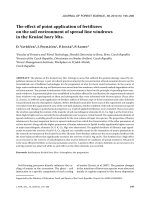
of sap flow. This is seen in Figure 4, where three examples of
the heat field images are shown as snapshots for the sap flow
dynamics during one particular day. It was August 11th, 1999,
when a more than 90% solar eclipse was shadowing the lime
tree at 1 pm. This eclipse is seen as a clear dip in the con-
tinuous sap flow recording in Figure 4, which clearly shows
the effect of solar radiation on evaporation, where the ambient
temperature did not change by more than 2
◦
C. The heat field
ellipses measured before and afterwards (time positions 1 and
2) are comparable, due to the comparable sap flow rate. How-
ever the tree temperature was slightly higher in the afternoon,
which led to a shift in the temperature color code. In the late
evening the heat field (time position 3) has contracted from
an elongated ellipse to a contracted one approaching a circle.
What can be learned from the analysis of such ellipses?
3.2.1. Evaluation of sap flow from infrared heat field
images
There are basically two phenomena involved in the dynam-
ics of the ellipses: The first is a thermal flux via thermal con-
duction J
T
, which is described by the equation (λ is the heat
transfer coefficient):
J
T
= −λ
dT
dx
= −λgradT. (5)
The second is a thermal flux via sap transport, J
TS
,which
is determined by the gradient of water potential Ψ
(dc
w
)/dx = gradΨ (6)
(c
w
= water concentration, Ψ = water potential, x = distance)
multiplied with an effective diffusion constant D, which con-
siders the effective friction in the Xylem water conduits, and
the heat H (in Ws mol
−1
) which is turned over at the heater
needle:
J
TS
= −HDgradΨ = −HJ
S
. (7)
Here J
S
is the sap flux. When the heat transport contributions
determine the dynamics and shape of the heat field, they have
to be related to dimensions within the elliptic heat field. Let us
concentrate on the distance between the central heating needle
and a selected isotherm of temperature T
S
parallel to the sap
flow direction. In absence of sap flow this axial distance should
be named a
ax
. In presence of sap flow there will be thermal
conduction along a similar distance a
ax
, but in addition there
will be a displacement of heat corresponding to the distance
between the two foci of the ellipse. It corresponds to the two
focal lengths 2e = 2
√
a
2
− b
2
,wherea and b are the small and
large axes of the ellipse respectively. It is the distance, which
makes the difference between absence of flux and presence of
flux:
J
TS
J
T
=
J
S
H
J
T
=
DHgradΨ
λgradT
=
(2e + a
ax
)
a
ax
(8)
from this relation one can deduce:
J
TS
= −HJ
S
= −DH gradΨ = −
(2e + a
ax
)
a
ax
λgradT. (9)
When the heat transfer coefficient λ is provided with a dimen-
sion of (Wm
−1
K
−1
), the heat H, which is transferred to the sap
with a dimension of (Ws mol
−1
), grad T with a dimension of
(km
−1
), then the sap flow J
s
will be equivalent to and have a
dimension of
J
S
= −
(2e + a
ax
)
a
ax
λgradT
H
mol
m
2
s
· (10)
From relation (7) it should be remembered, that the heat H
with the dimension Ws mol
−1
has been defined as the negative
ratio of heat transport via sap transport J
TS
to the sap flux J
S
.It
can be assumed that the heat flux at the heat probe is increasing
proportional to the provided electrical heating power P
H
and
to the concentration of passing water, the sap flux J
S
. The heat
can therefore be written as
H =
kP
H
J
S
J
S
= kP
H
(11)
Infrared images of heat field and sap flow 657
Figure 3. ( A) IR-image of the heat field in the stem xylem around a linear heater under zero-flow conditions: M – center of an ellipse, F1, F2
– foci of an ellipse and e – its eccentricity. Red horizontal line passes through axes of the heater and center of an ellipses (iso-temperature
profiles). (B) and (C) IR-images of the heat field with increasing sap flow rates (shown by blue arrows). Red horizontal line marks the axis of
the heater which position gradually moves with increasing flow rates from the center M (at zero-flow conditions) towards the first focus F1.
Area, limited by the same isotherm, remains constant, while eccentricity of ellipses increases with increasing sap flow rates.
Figure 4. First two infrared images of heat field were recorded under the same flow rates at 11 h 30 min (left) and at 14 h 00 min (middle).
Shape of iso-temperature profile (thick curve line) with temperature equal to 17.7
◦
C (left image) is identical to that with temperature equal
to 20
◦
C (right image) and was characterized by the same eccentricity of ellipse. Increase of temperature was caused by increase of stem tem-
perature. Comparably visible range of iso-temperature profiles (compare upper parts of ellipses) demonstrates similar temperature differences,
corresponding to similar sap flow rates. Infrared image of the heat field (right image) was made at 22 h 22 min (vertical line 3) under the same
stem temperature as in the morning (vertical line 1). No one iso-temperature profiles in the right image correspond to those demonstrated on the
left and middle images. Iso-thermal profile, limited by the ellipse with the area equal to those on the left and middle images, is characterized
by lower eccentricity.
658 H. Tributsch et al.
Figure 5. Set of ellipses with increasing eccentricities corresponding
to increasing sap flow rates. Isotherms with equal area are presented.
Positioning differential thermocouples according different methods is
shown as follows: HD-method measures dT_Granier; HFD-method
measures dTsym and dTas.
(k is a proportionality factor determined by geometry and hy-
drodynamic conditions) and the sap flux becomes:
J
S
=
(2e + a
ax
)
a
ax
λgradT
kP
H
mol
m
2
s
· (12)
This relation now has to be interpreted. It contains dimen-
sional parameters of the ellipses developing under negligible
and given sap flow. They can be provided in real dimensions
(for a given isotherm), since they cancel out. The formula also
contains the heat transfer coefficient λ, which has to be pro-
vided parallel to the tree axis. The heating power P
H
trans-
ferred should be the real power loss or power turnover of the
heating needle in Ws per mol of sap. In order to simplify the
measurement this value P
H
should be kept constant during the
experiment. It remains to be examined how the temperature
gradient has to be determined. Since it controls heat conduc-
tion one should take the temperature difference between the
heating needle and the selected temperature isotherm divided
by the axial distance a
ax
.
Equation (12) makes basically sense because the sap flow
rate is, as Figure 5 shows, indeed essentially reflected in the
elongation of isothermal ellipses from their thermal focus.
The more power P
H
is being introduced through the heating
needle, the bigger will also become the temperature gradient
gradT.
A comparatively simple way of handling Equation (12)
during measurements involves the stable control of the quan-
tity P
H
, the power turnover in the heat probe, with the dimen-
sion of Ws mol
−1
. It should remain constant, regardless of the
amount of sap transported, which takes away the heat. This
could be reached by Equation (1) controlling the power input
electronically or (2) by applying sensor materials with electri-
cal resistances which do not change with temperature. Exam-
ples are Konstantan (55% Cu, 45%Ni) or Manganin (86%Cu,
12%Mn, 2% Ni). Then under constant voltage input the power
turnover will remain also constant. The latter is usually applied
in present heat probe sensors. A constant thermal energy input
has an advantage with respect to variations of sap flow during
the day in different tree rings in certain tree species. This kind
of sap flow variations does not affect the energy turnover and
thus the applicability of Equation (12). Heat sensors placed in
different depth should give consistent information on the sap
transport profile.
3.2.2. Analysis of sensor techniques from point of view
of ellipse theory
Figure 5 compares the placement of heat sensors in the HD
[7] and the HFD [17] techniques. It is seen that for catching the
dynamics of ellipses, the sensors are not ideally placed. The
sensors placed below the heater do not appear to catch much of
the changes. The asymmetric sensor placed horizontally from
the heater will be exposed to a strong change of temperature,
but at a very high sap flux rates it may be left outside the main
thermal dynamics.
The sensors above the heater may on the other hand be left
in a quite indifferent region between the foci of the isothermal
ellipses.
What could, in fact, be a reliable strategy towards a rea-
sonably accurate continuous determination of sap flow rates
through the dynamics of ellipses?
Since it could be shown that the dynamics of ellipses of
isotherms can give access to sap flow monitoring, ways should
be found to determine the parameters of these ellipses. For
long-term sap flow monitoring the challenge obviously is
therefore to make temperature measurements, in an as simple
as possible arrangement, which allow to determine quantita-
tively the axes a,andb of the ellipse and thus the eccentric-
ity e (compare Fig. 2). In this way the complete ellipses could
be determined.
The simplest approach may possibly be the following:
one sensor horizontally displaced from the heating needle is
needed as well as a temperature sensor array along the axis
Infrared images of heat field and sap flow 659
Figure 6. Simplified scheme explaining the proposed positioning of
temperature sensors for determination of the parameters needed for
calculating ellipse shaped isotherm.
vertically above the heating needle. This could be a series of
heat sensors (at least two of them), which are wired in such
a way that they can measure temperature as a function of dis-
tance (Fig. 6). The temperature would be determined along
this array and a simple linear interpolation could be made to
determine at what position above the heater the temperature
corresponds to that measured horizontally from the heater (dis-
tance p given in Eq. (1)).
The measurement problem would be relatively simple: the
heat sensor at the level of and horizontally displaced from the
heating needle measures a temperature T
x
and along the array
in direction of the axis the position of the same temperature T
x
has to be located.
As seen from Figure 6 we have thus recognized the form of
the ellipse: the horizontal distance of the temperature sensor
from the heating needle gives the segment p = b
2
/a and the
distance of the T
x
position above the needle gives the distance
a (half main axis) + e (eccentricity) = z = a +
√
a
2
− b
2
. (13)
We have thus two measured distances and two variables, a
and b. This means, the ellipse is thus fully determined as well
as all other ellipses describing isothermal lines with different
temperatures.
From (1) it follows:
b
2
= pa. (14)
Inserted into (11) it follows
z = a
1 +
1 −
p
a
· (15)
Since p and z are measured distances, a can be calculated
numerically from (15) and inserted into (14) for calculation
of b.
Basically, the HFD technique may be easier changed for
measuring dynamics of ellipses in such a way that the sensor
below the heater is displaced to a position above the heater and
one to three more sensors are added along the axis of the tree
trunk.
With a small computer program, which determines the tem-
perature at the asymmetrical sensor, horizontally displaced
from the heater, and thereafter determines the position of the
same temperature at the sensor array, the necessary calcula-
tions to determine the temperature profiles for the measured
temperature and of all other temperatures around the heating
needle could be performed in a straightforward way. In this
way the needed quantity e, the eccentricity, could be calculated
and monitored so that the sap flow determined by relation (12)
can be found (after a
ax
, the horizontal distance between the
central heater and the horizontally displaced sensor is inserted
and gradT = (T
P
− T
x
)/a
x
), the temperature gradient, is deter-
mined at zero sap flow conditions).
There are also other sensor geometries imaginable, which
may allow determination of the dynamic shapes of ellipses,
which reflect the sap flow patterns. They appear to be more
complicated. It may also be possible to design a measure-
ment system in which the power loss at the central heater kP
H
(Eq. (12)) is not kept constant but electronically measured, so
that the sap flow J
S
can be computed. Only experience with
the newly to be developed hardware will show what degree
of perfection these proposed improved sap measurement tech-
niques may develop.
In conclusion it may be summarized that more accurate
and more reliable experimental methods are needed to mon-
itor cohesion-tension water dynamics for overcoming contro-
versial discussions. The dynamics of heat transport in the mor-
phologically complex environment of the sap-transporting tree
Xylem is highly complex. Experiments combining heat sen-
sors and heat field imaging have opened a reasonable path
towards handling the problem, as shown in this publication,
and added to the notion that sap water in trees is actually
pulled [27]. As the presented results and discussions have
shown, the empirical positioning of heat sensors in conven-
tional HD [7] and HFD [17] measurement approaches is not
optimal in context of the theory of ellipses and with respect to
a rational understanding of the theoretical background of mea-
surements.The presented concepts provide for the first time a
mathematical-physical basis for understanding the measure-
ments. However, new measurement hardware has to be devel-
oped and tested for a comparative quantitative evaluation. This
will be attempted in a forthcoming paper.
Acknowledgements: This study was performed within a project of
the Hahn-Meitner Institute and partially within the framework of
WATERUSE project (EVK1-CT-2000-00079).
660 H. Tributsch et al.
REFERENCES
[1] Anfodillo T., Sabatti M., Sigalotti G.B., Valentini R., An application
of infrared thermal image to monitor water transport in plants, in:
Carlomagno G.M., Corso C. (Eds.), Advanced Infrared Technology
and Applications, Firenze, 1992, pp. 427–437.
[2] Anfodillo T., Sigalotti G.B., Tomasi M., Semenzato P., Valentini R.,
Application of thermal imaging in the study of sap flow in woody
species, Plant Cell Environ. 16 (1993) 997–1001.
[3] Angeles G. et al., The Cohesion-Tension Theory, New Phytologist,
Forum, www.newphytologist.org.
[4]
ˇ
Cermák J., Deml M., Penka M., A new method of sap flow rate
determination in trees, Biol. Plant. 18 (1973) 105–110.
[5] Cohen Y., Thermoelectric methods for measurement of sap flow
in plants, in: Standhill G. (Ed.), Advances in Bioclimatology,
Springer-Verlag, 1993, pp. 63–89.
[6] Daum C.R., A method for determining water transport in trees,
Ecology 48 (1967) 425–431.
[7] Granier A., A new method to measure the raw sap flux in the trunk
of trees, Ann. For. Sci. 42 (1985) 193–200.
[8] Granier A., Anfodillo T., Sabatti M., Cochard H., Dreyer E., Tomasi
M., Valentini R., Breda N., Axial and radial water flow in the trunks
of oak trees: a quantitative and qualitative analysis, Tree Physiol. 14
(1994) 1383–1396.
[9] Groot A., King K.M., Measurement of sap flow by the heat balance
method: numerical analysis and application to coniferous seedlings,
Agric. For. Meteorol. 59 (1992) 289–308.
[10] Holbrook N.M., Burns M.J., Field C.B., Negative xylem pressures
in plants: a test of the balancing pressure technique, Sci. 270 (1995)
1193–1194.
[11] Huber B., Schmidt E., Weitere thermoelektrische Untersuchungen
uber den Transpirationsstrom der Baume, Tharandter Forstliche
Jahrsblad 87 (1936) 369–412.
[12] Ittner E., Der Tagesgang der Geschwindigkeit des Transpirations
stromes im Stamme einer 75-jahrigen Fichte. Oecol. Plant. 3 (1968)
177–183.
[13] Karmanov V.G., Ryabova E.P., Instrument for registration of rela-
tive sap flow rate in plant, Ann. Rev. Agronom. Physics, Leningrad,
16 (1968) 81–87 (in Russian).
[14] Kucera J.,
ˇ
Cermák J., Penka M., Improved thermal method of con-
tinual recording the transpiration flow rate dynamics, Biol. Plant. 19
(1977) 413–420.
[15] Marshall D.C., Measurements of sap flow in conifers by heat trans-
port, Plant Physiol. 33 (1958) 385–396.
[16] Nadezhdina N., Cermák J., The technique and instrumentation for
estimation the sap flow rate in plants, Patent No. 286438 (PV-1587-
98), 1998 (in Czech).
[17] Nadezhdina N., Cermák J., Nadezhdin V., Heat field deformation
method for sap flow measurements, in: Cermák J., Nadezhdina
N. (Eds.), Measuring Sap Flow in Intact Plants, Proc. of 4th Int.
Workshop, Zidlochovice, Czech Republic, IUFRO Publications,
Brno, Czech Republic, Publishing House of Mendel University,
1998, pp. 72–92.
[18] Nadezhdina N., Tributsch H., Cermák J., Infra-red images of heat
field around a linear heater and sap flow in stems of lime trees un-
der natural and experimental conditions, Ann. For. Sci. 61 (2004)
203−213.
[19] Pickard W.F., Puccia C.J., A theory of the steadystate heat step
method of measuring water flux in woody plant stems, Math. Biosci.
14 (1972) 1–15.
[20] Pockman W.T., Sperry J.S., Oleary J.W., Sustained and significant
negative water-pressure in xylem, Nature 378 (1995) 715–716.
[21] Sakuratani T., A heat balance method for measuring water flux in
the stem of intact plants, J. Agric. Meteorol. (Japan) 37 (1981)
9−17.
[22] Smith D.M., Allen S.J., Measurement of sap flow in plant stems, J.
Exp. Bot. 47 (1996) 1833–1844.
[23] Steudle E., Trees under tension, Nature 378 (1995) 663–664.
[24] Steudle E., The cohesion-tension mechanism and the acquisition of
water by plant roots, Ann. Rev. Plant Physiol. Mol. Biol. 52 (2001)
847–875.
[25] Swanson R.H., Numerical and experimental analysis of implanted-
probe heat-pulse theory, Ph.D. thesis, University Alberta, Canada,
1983.
[26] Swanson R.H., Significant historical developments in thermal meth-
ods for measuring sap flow in trees, Agric. For. Meteorol. 72 (1994)
113–132.
[27] Tributsch H., Cermak J., Nadehdina N., Kinetic studies on the ten-
sile state of water in trees, J. Phys. Chem. 109 (2005) 17693–17707.
[28] Tyree M.T., The Cohesion-Tension theory of sap ascent: current
controversies, J. Exp. Bot. 48 (1997) 1753–1765.
[29] Tyree M.T., The ascent of water, Nature 423 (2003) 923–923.
[30] Tyree M.T., Cochard H., Vessel content of leaves after exci-
sion: a test of the Scholander assumption, J. Exp. Bot. 54 (2003)
2133−2139.
[31] Vieweg G.H., Ziegler H., Thermoelektrische Registrierung der
Geschwindigkeit des Transpirationsstromes, Ber. Deut. Bot. Ges.
73 (1960) 221–226.
[32] Zimmermann U., Schneider H., Wegner L.H., Haase A., Water as-
cent in tall trees: does evolution of land plants rely on a highly
metastable state? New Phytol. 162 (2004) 575–615.
To access this journal online:
www.edpsciences.org/forest