An Experimental Approach to CDMA and Interference Mitigation phần 6 docx
Bạn đang xem bản rút gọn của tài liệu. Xem và tải ngay bản đầy đủ của tài liệu tại đây (866.28 KB, 29 trang )
128 Chapter 3
500
400
300
200
100
0
40x10
3
3020100
Normalized Time (Symbols)
L=64, K=32
C/I=-6 dB, P/C=6 dB
E
b
/N
0
=2 dB
J
BAID
=2
-15
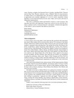
Figure 3-37. CPRU acquisition sample.
1
2
3
4
5
6
7
8
9
10
1086420
E
b
/N
0
(dB)
L=64, K=32
C/I=-6 dB, P/C=6 dB
J
BAID
=2
-15
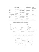
Figure 3-38. Accuracy of CPRU phase estimates.
3. Design of an All Digital CDMA Receiver 129
0.001
2
3
4
5
6
0.01
2
3
4
5
6
0.1
2
3
4
5
6
1
BER
1086420
E
b
/N
0
(dB)
L=64, K=32
C/I=-6 dB, P/C=6 dB
J
BAID
=2
-15
AFC, PLL on
ideal
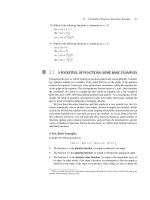
Figure 3-39. BER performance in the presence of frequency and phase errors.
where
ˆ
() () ()kkk'T T T
is the residual phase error at step k, and
{±1±j}
k
c is the kth transmitted QPSK symbol on the useful traffic
channel. If we look at
()zk
as a function of ()k'T we easily find that it is
not dependent on the particular value of
k
c , and it is periodic with period
/2S
^
cos sinzk A k k ª'Tºª'Tº
¬¼¬¼
`
cos sinkkª'Tºª'Tº
¬¼¬¼
(3.99)
(recall that
0A ! by definition). As is seen from the plot of (3.99) in Figure
3-40,
()zk
attains its maximum value 2A when the phase error is a multiple
of
/2S , i.e., when the phase loop is in lock. Re-considering noise and MAI,
()zk
needs filtering to yield a reliable lock metrics as in (3.97).
Before the AFCU and the CPRU have attained lock
()zk
is affected by a
frequency offset. In such a condition
()k'T has a linear evolution with time,
and therefore the oscillating plot in Figure 3.40 is in a sense ‘swept’ on the
phase x-axis. If the forgetting factor is small, i.e.,
1
L
J, the lock metrics
130 Chapter 3
()lk
in (3.97) tends to be equal to the time averaged value of
()zk
4
4
1
2cos d 1.8
2
lk A A
S
S
|'T'T|
S
³
. (3.100)
2.5
2.0
1.5
1.0
z(k)/
A
-180 -90 0 90 180
'T(k) (degrees)
Figure 3-40.
kz
vs. the phase error
k'T
.
Our lock detection criterion will be a comparison of ()lk with a suited
threshold ranging between 1.8A and 2A. If the threshold is crossed, the phase
error should be stable and close to one of the four lock point multiples of
ʌ/2.
Figures 3-41 and 3-42 show the evolution of the lock metrics and of the
AFCU frequency estimate starting from receiver switch on in the following
condition:
i)
64L ;
ii)
32K active users;
iii)
0
/2dB
b
EN
;
iv)
/6dBCI ;
v)
/6dBPC ;
vi) AFCU:
19
AFCU
2
J ,
0.1
s
TQ
. The frequency step size is intentionally
set from the very start to its steady state value. This has the effect of
lengthening the frequency acquisition time to show better the two
different DC levels attained by
()lk in the two different out of lock and
in lock conditions;
vii) CPRU:
9
CPRU CPRU
2
J U
;
3. Design of an All Digital CDMA Receiver 131
viii) EC-BAID:
15
BAID
2
J
;
ix) lock detector:
13
2
L
J
.
1.85
1.84
1.83
1.82
1.81
1.80
1.79
1.78
1.77
1.76
1.75
Lock detector evolution
500x10
3
4003002001000
Normalized Time (Symbols)
L=64, K=32
C/I=-6 dB, P/C=6 dB
E
b
/N
0
=0 dB
lock det.
O
H
O
L
Figure 3-41. Lock metrics evolution @
0
0/
b
EN dB.
0.15
0.10
0.05
0.00
Frequency estimates
500x10
3
4003002001000
Normalized Time (Symbols)
L=64, K=32
C/I=-6 dB, P/C=6 dB
E
b
/N
0
=0 dB
QT
s
=0.1
Figure 3-42. Frequency acquisition @
0
0/
b
EN dB.
Joint evaluation of Figures 3-41 and 3-42 is quite instructive. It is seen
that in a first stage the frequency error is quite large (
0.10
s
TQ ), the
CPRU has no way to lock in, and the lock metrics (initialized at
(0) 1.75l )
have a short acquisition and settles at the expected out of lock value 1.8. As
soon as the AFCU acquisition is over, and thus the frequency error is small
132 Chapter 3
(roughly
5
210k
), the CPRU starts acquiring lock, and in parallel (after a
short CPRU acquisition time) the lock metrics rapidly attains the lock value
1.82. Unfortunately this value is substantially smaller than the theoretical
peak value of 2 in Figure 3-40 owed to noise induced biasing. We can
therefore use a strategy of comparison with hysteresis to detect “out of
lock
oin lock” and “in lockoout of lock” transitions based on the two
threshold values
1.8
L
O and 1.815
H
O . This prevents the circuit to detect
false events like the one we would find in Figure 3-43 at
5
4.2 10k #u
should we use a single threshold at
H
O with no hysteresis.
1.90
1.85
1.80
1.75
LLock detector evolution
500x10
3
4003002001000
Normalized Time (Symbols)
L=64, K=32
C/I=-6 dB, P/C=6 dB
E
b
/N
0
=4 dB
O
H
O
L
lock det.
Figure 3-43. Lock metrics evolution @
0
0/
b
EN dB.
Concerning the bias phenomenon for the out of lock and in lock values of
()lk mentioned above, we found that the out of lock value 1.8 is very
marginally affected by the operating condition in terms of SNIR, probably
owing to the implicit time averaging effect on
()zk
we have discussed.
Instead, the in lock value tends to grow when the SNIR improves. Thus, the
same threshold values determined for the worst case in Figure 3-43 can be
safely re-used in conditions of better SNIR.
3. SIGNAL DETECTION AND INTERFERENCE
MITIGATION
Implementation of a single-channel interference mitigating CDMA
detector represents the main novelty of the MUSIC project. In this Section
we present the interference mitigating feature of the MUSIC receiver which
is based on the EC-BAID algorithm to be detailed hereafter.
3. Design of an All Digital CDMA Receiver 133
3.1 EC-BAID Architecture
We start with the analytical description of the signal at the receiver input,
assuming that K user traffic channels in DS/SS format are code multiplexed
in A-CDMA mode (see Chapter 2). The generic kth CDMA user transmits a
stream of complex-valued information bearing symbols, denoted as
,,
() () j ()
kkp kq
au a u a u
. The symbols, which belong to a QPSK alphabet
(i.e.,
,,
(), () { 1}
kp kq
auaur ) and run at symbol rate
1/
s
s
R
T
, are spread
over the frequency spectrum by multiplication with a binary signature code,
denoted as
() { 1}
k
c rA
, with period L and running at chip rate
1/
cc
R
T
.
The signature is actually a short code as its repetition period L spans exactly
one symbol interval:
s
c
TLT . Chip rate symbols are eventually shaped by
a transmit filter with SRRC impulse response
()
T
g
t
. At the receiver side,
after baseband conversion, the overall signal, denoted as
()rt , is made of K
CDMA channels plus additive noise
()nt as follows
1
K
kk k c s k
ku
rt Pa us mT uT
f
f
W
¦¦
^
`
exp j 2
kc k
mT n tSQI
, (3.101)
where
k
P
is the RF power of the kth channel and ()
k
s
t is the relevant
spreading signature defined as
1
0
L
kkTc
s
tcgtT
¦
A
AA
. (3.102)
In (3.101)
k
W ,
k
I and
k
Q are the time delay, the carrier phase shift, and
the frequency offset of the generic k-th traffic channel w.r.t. the useful traffic
signal, which, without loss of generality is assumed to be channel 1. We
assume for now that the carrier frequency error relevant to channel 1 is
perfectly compensated for by means of an ideal AFC subsystem (i.e.,
1
0f'
) and that perfect chip timing recovery is performed (i.e.,
1
0W
).
The signal
()rt is then sent through a baseband filter with impulse response
()
R
g
t performing Nyquist’s SRRC chip matched filtering, followed by chip
time sampling (or interpolation in the case of a digital implementation). The
signal samples taken at time
mc
tmT at the output of the CMF are thus
|
c
R
tmT
ym rt g t
. (3.103)
The chip time signal
ym
is then input to the EC-BAID data detector
that was introduced in Section 2-5. We will described here the detector in
134 Chapter 3
more detail, starting back from the very fundamentals, just to make this
section as much self-contained as possible. As detailed in [Rom97], the EC-
BAID uses a three-symbol observation window to detect one information
bearing symbol. In the subsequent analytical description we will use the
superscript
e
to denote a 3L-dimensional vector (also termed ‘extended
vector’ as opposed to ‘non-extended’ L-dimensional vectors), the superscript
T
to denote transposition, and the asterisk
*
to denote complex conjugation.
The 3L-dimensional array of CMF samples observed by the detector is given
by
01
0
31 1
()
() ()
()
e
e
e
L
yr
rr
yr
ªº
ªº
«»
«»
«»
«»
«»
«»
¬¼
¬¼
y
yy
y
#
, (3.104)
where
[( ) ]
[(( ) 1) ]
[(( ) 2) ]
[(( ) 1) ]
c
c
w
c
c
yr wLT
yrwL T
ryrwLT
yrwLL T
ªº
«»
«»
«»
«»
«»
«»
¬¼
y
(3.105)
with 1,0,1
w . The EC-BAID is a linear detector operating on the chip rate
sampled received signal
y(m) to yield the symbol rate signal b(r) as follows
1
T
ee
br r r
L
hy
, (3.106)
where ( )
e
rh is the 3L-dimensional array of the complex-valued detector
coefficients. It is apparent that detection of each symbol calls for observation
of
three symbol periods (i.e., the current, the leading, and the trailing ones)
which represent the so called
observation window (
LEN
W ). This suggests the
three-fold parallel implementation of the detector sketched in Figure 2-20,
and repetead here in Figure 3-44, wherein the first detector unit processes the
(1)r th, the r th and the (1)r th symbol periods for the detection of the
r th symbol, the second unit processes the r th, the (1)r th and the
(2)r th periods, for the detection of the (1)r
th symbol, and the third unit
processes the
(1)r th, the (2)r th and the (3)r th periods, for the
detection of the
(2)r th symbol. The structure of the detector units will be
outlined in the sequel. Also, in the algorithm description we will assume a
3. Design of an All Digital CDMA Receiver 135
normalized observation window
3
LEN
W , whilst further considerations
about the selection of the optimum value of
LEN
W
will be reported later in
Section 4.1.
Figure 3-44. EC-BAID top level functional block.
The output stream of soft values for data detection is obtained by
sequentially selecting the three detector unit outputs at rate 1/
T
s
by means of
a multiplexer. We need thus a further clock reference ticking at the so called
Super-Symbol rate
SS
1/(3 )
s
R
T , i.e., once every three symbols. Taking this
into account, the sample at the output of the
n-th detector unit ( 1, 2, 3n ) is
,
1
31 31
T
en e
bsn s sn
L
hy , (3.107)
with
s running at super-symbol rate. To achieve blind adaptation the
complex coefficients
,en
h of each detector are anchored to the user signature
sequence, represented by the
L–dimensional array c containing the chips
1
()c A of the useful signal 1. The anchoring condition is obtained as follows
[Rom97]. First, we decompose
,en
h in two parts
,,en e en
s
s hcx, (3.108)
where
136 Chapter 3
e
ªº
«»
«»
«»
¬¼
0
cc
0
,
0
1
1L
c
c
c
ªº
«»
«»
«»
«»
«»
¬¼
c
#
,
,
01
,
0
,
31 1
en n
en n
en n
L
x
s
s
s
x
s
ªºª º
«»« »
«»« »
«»« »
¬¼¬ ¼
x
xx
x
#
. (3.109)
where we set
1i
cci for simplicity. We impose then the following
‘anchor’ constraint
0
Tn
w
cx (3.110)
with 1,0,1
w , and the optimum MMOE configuration of the detector is
found through application of a recursive update rule for the detector
coefficients. As is detailed in [Rom97], the error signal in the recursion for
detector
n is given by
1
,
0
1
n
en n
n
s
s
s
s
ªº
«»
«»
«»
¬¼
e
ee
e
, (3.111)
where
*
*
31
3131
T
w
n
ww
sn
s bsn sn
L
ªº
«»
«»
¬¼
yc
ey c
(3.112)
1, 0,1
w . If the three detector units were running independently, the
update equation for each detector would simply be [Rom97]
,,,
1
en en en
s
ss Jxxe
, (3.113)
with
s ticking at super-symbol rate and where J is the adaptation step
which in the following will be also referred as
BAID
J .
Equation (3.110) forces the so called ‘chunk’ orthogonality condition on
all three adaptive detector components
n
w
x , leading to a detector which we
call EC-BAID-I, whose structure is outlined in Figure 3-45. On the other
hand, we recognize that there is little information about the symbol to be
detected in the signal segments spanned by
1
n
x and
1
n
x . Therefore we can
also limit the orthogonality constraint to
0
n
x only, i.e.,
0
0
Tn
cx . In so doing,
the components
1, 1
n
x
and
1,1
n
x
have more degrees of freedom for minimizing
3. Design of an All Digital CDMA Receiver 137
the selected error cost function as detailed in [Rom97]. Such a modified EC-
BAID algorithm, dubbed EC-BAID-II, is formalized by
,,
31 3 3 1
en en
ssbsnªº J
¬¼
xx
*
*
31
31
T
ee
ee
sn
sn
L
ªº
«»
«»
¬¼
yc
yc
(3.114)
Figure 3-45. EC-BAID-I detector:
,en
i
x
and
e
i
y
are the elements of
,en
x
and
e
y
, respectively.
with the following reduced anchoring condition
,
0
T
een
cx . (3.115)
The EC-BAID-II (whose architecture is depicted in Figure 3-46) reveals
enhanced robustness against MAI [Rom97]. On the other hand, the EC-
BAID-I is more resilient to the lack of randomness for the modulating data
b
b
’
J
-
+
-
+
+
+
,n
ci
138 Chapter 3
and thus it can be conveniently used in all situations where no data
scrambling is possible. For this reason the proposed MUSIC receiver
architecture allows for EC-BAID type I or II programmability by setting a
proper input control signal.As shown above, the EC-BAID-I and -II versions
(Figures 3-45 and 3-46) require in principle three separate units, each with
its own ‘local’ copy of
,en
x . This is not necessarily true if we work out
different variants of the update algorithm (3.113) and of the output computer
(3.106).
Figure 3-46. EC-BAID-II detector:
,en
i
x
and
e
i
y
are the elements of
,en
x
and
e
y
, respectively.
The final architecture of EC-BAID-I and –II, whose top level diagram
sketched in Figure 3-47, follows in fact the so called ‘Select and Add’
(S&A) arrangement. In particular, the S&A architecture uses a clock of
period
/3
c
T (over-clock) to re-use the arithmetical part of the circuit three
times for each symbol period. This allows to calculate the output
b(r)
s
get the
b
b
’
+
+
+
-
,n
J
+
-
ci
3. Design of an All Digital CDMA Receiver 139
entire dot product (3.106) and update, a single, ‘unique’ vector
e
x , shared by
all of the three pipelined detectors, and all this in a single period
T
s
.
Figure 3-47. Optimized architecture of the EC-BAID ‘Select and Add’.
As is depicted in Figure 3-47, blocks 1 and 2 evaluate the correlations
1
()
T
ryc and () ()
eTe
rrxy, respectively, yielding the output strobe b(r) at
symbol rate. The vector
e
x
is stored in memory (item 6 in Figure 3-47) and
each of its
3L elements is updated every /3
c
T . In particular, during the i-th
chip period within the
r-th symbol interval, the coefficients of
e
x
relevant to
the
i-th chip of y(r-1), y(r), and y(r+1) are updated. A dedicated memory
(item 7) is used to store the most recent 3
L input chips. Multiplexers 5 and 8
properly re-align the internal dataflow, while multiplexer 3 selects the
desired EC-BAID algorithm version (type-I or -II). The update equation for
EC-BAID-II is
b(
r
)
b
’
(
r
)
-
+
J
x
-
+
ci
,n
140 Chapter 3
*
1
*
1
1
111
T
w
ww w w
r
rrbrr
L
ªº
J G
«»
«»
¬¼
yc
xx y c
, (3.116)
where
1, 0,1w and
w
G
is a Kronecker delta such that
1
w
G
if 0w
and 0
w
G if
1w r
. Therefore the output of multiplexer 3 is set to zero
(instead of to
T
w
yc) for EC-BAID-II (see Figure 3-47). The timing diagram
of the S&A main signals is shown in Figure 3-48. The Automatic Gain
Control (AGC) on the feedback loop (block 4) is needed in order to keep the
amplitude |
b| of the output signal constant, irrespective of the different SNIR
operating condition.
The equations relevant to the S&A implementation of the EC-BAID-I
and –II are summarized in Table 3-3, where
r is a symbol time index.
3.2 EC-BAID Optimization
The fixed point ASIC implementation of the S&A introduces truncation
errors with respect to theoretical performance which is computed assuming
floating point arithmetic. Our adaptive architecture is based on a feedback
loop, and so the quantization errors may have detrimental effects on the
overall algorithm convergence. In particular, quantization effects may
destroy the orthogonality between the vector of the error signals
e
e
, which is
used to generate the adaptive vector
e
x , and the code sequence vector
e
c
.
As a consequence, owing to finite arithmetic, the components of
e
x may
drift and indefinitely increase, thus causing in the long run saturation and
failure of the detector. To prevent this, it is mandatory to calculate the error
signal
e
e (based on the quantized values y
e
and b as in (3.117) with full
precision arithmetic
*
*
T
ee
ee e
r
rbr r
L
ªº
«»
«»
¬¼
yc
ey c
. (3.117)
This means that, starting from quantized values
y
e
and b, the processing
relevant to
e
e (and so
e
x ) has to be performed with an internal word length
dictated by the whole signal dynamics, so that no further truncation is
introduced. This reveals very demanding in terms of hardware complexity
2
,
but, as we show here for the simplified case of 1 bit quantization
3
of ( )
e
rx ,
2
The RAM memory needed to store the 3L components of x
e
accounts for nearly half the
overall EC-BAID silicon area.
3
The derivation is performed for simplicity in the case of 1 bit truncation, but can be easily
generalized to n bit with n > 1.
3. Design of an All Digital CDMA Receiver 141
has intolerable effects. Starting from (3.117) with
7
128 2L
, the internal
‘full precision’ (
f.p.) representation of the error signal can be re-arranged as
follows
*7 *
2
T
eeeee
fp
rbrr r
ªº
¬¼
eyycc
(3.118)
Figure 3-48. Timing diagram of the main signals for the ‘Select and Add’ architecture.
such that the 1 bit ‘truncated’ (tr.) version of the error signal is
ci
c(i+1)
e-1,i e0,i e1,i
e-1,(i+1) e0,(i+1) e1,(i+1)
ew,i
ew
x-1,i x0,i x1,i
x-1,(i+1) x0,(i+1) x1,(i+1)
xw,i
xw
y(r-1) y(r)
y(r+1)
y(r+2)
y(r+3)
142 Chapter 3
*7 *
2
T
eeeee
fp
tr
ee
fp
rbrr r
rr
«»
ªº
«»
¬¼
¬¼
eyycc
e ǻe
(3.119)
where ¬¼
tr
means ‘zero forcing’ of the LSB of
()
e
f
p
re .
Table 3-3. EC-BAID-I and -II equations for the ‘Select and Add’ architecture.
EC-BAID-I and –II
detector output
1
with
T
ee e e e
br r r r r
L
hy h x c
EC-BAID-I
update of
1
e
x
11
www
rrr J xxe
*
*
T
w
ww
r
rbr r
L
ªº
«»
«»
¬¼
yc
ey c
1, 0, 1w
EC-BAID-II
update of
1
e
x
11
eee
rrr J xxe
*
*
T
ee
ee e
r
rbr r
L
ªº
«»
«»
¬¼
yc
ey c
11
00
11
,,
ee e
rr
rr rr
rr
ªº ªº
ªº
«» «»
«»
«» «»
«»
«» «»
«»
¬¼
¬¼ ¬¼
0x e
cc x x e e
0x e
In (3.119),
()
e
f
p
re is orthogonal to
e
c by construction (i.e.,
() 0
eT e
fp
r ec
), whilst the same consideration does not apply to the
quantization term ( )
e
rǻe . In particular, taking into account that the LSB of
the term (
*7
()2
e
r y ) in (3.119) is necessarily zero, ǻ ()
e
re can be expressed
as follows
ǻ
ee e
tr f p
rr r ee e
**
()
TT
eee eee
tr
br r br r
«»
¬¼
ycc ycc
. (3.120)
To simplify the expression above, we let
*
T
ee
rbr rD yc (3.121)
such that
3. Design of an All Digital CDMA Receiver 143
eee
tr
rr r
«»
D D
¬¼
ǻecc (3.122)
Consider now that
e
c
is an extended vector whose central section with
0w
has components with values +1 or –1. The product with D(r) then
gives two different possible results: if D(r) is even, 1 bit truncation does not
introduce any error and we have
.
0
eee
tr
rrr
«»
D D
¬¼
ccǻe
; (3.123)
if
()rD is odd, 1 bit truncation is equivalent, considering a 2’s complement
representation, to subtracting 1 to each non-zero vector element, thus
>
@
.
00 0 111 1 00 0
T
ee
tr
rr
«»
D D
¬¼
cc"""
>
@
00 0 111 1 00 0
T
e
r ǻe """. (3.124)
The vector ( )
e
rǻe is made of a component which is orthogonal to
e
c
and of a component d
e
e which is not. The first will have no effect on the
overall performance, whilst the second, being characterized by elements all
of the same sign, will build up an accumulation error. This will impair
algorithm convergence. In particular,
d
e
e
is given by
>@
111 1
ǻ
d0
T
T
ee
eee
r
r
LL
§·
§·
¨¸
¨¸
z
¨¸
¨¸
©¹
©¹
c
ec
ecc
"
. (3.125)
The term ([111 1] )
T
c" in (3.125) is simply the sum of the code chips
1
()c A . So d
e
e is zero only if the sequence c is balanced, that is, it contains an
equal number of
1
and
1
. As previously stated, the MUSIC receiver
supports the use of extended PN sequences overlaid to WH signatures. This
superposition generates unbalanced codes for almost all of the possible
combinations. Thus it is very likely, in the case of 1 bit truncation, to have
d()0
e
r ze .
Figure 3-49 shows the estimated BER performance of the EC-BAID
obtained with
128L
,
64K
,
0
/5dB
b
EN , /6dBCI and on a
simulation run of 20 Msymbols. The lower (almost horizontal) curve was
obtained with no truncation in the evaluation of
e
e , whilst the upper one was
obtained with just 1 bit error in the internal word length dimensioning. In the
latter case, the term
>
@
111 1
T
c" of (3.125) is equal to 16, and so every time
144 Chapter 3
D(r) is odd, the component of
()
e
rx
which is not orthogonal to
e
c
is
incremented by a ‘drift’ term
16 /128
e
c .
Figure 3-49. BER system performance with and without error signal truncation effects.
As is seen in Figure 3-47, an internal AGC on the EC-BAID feedback
loop is needed in order to keep the output amplitude |b| constant at different
SNIR operating conditions. The amplitude of the received signal varies
according to the amplitude of the different interfering user signals (
k
P
),
and according to the effects of the channel noise n(mT
c
). This is more clearly
apparent if we assume synchronous multiplexing
11 1
//
L
ym Pa m Lc m
2
//
K
kk k
L
k
P
amLcm nm
¦
, (3.126)
where
()nm is a Gaussian noise sample. In order to better exploit the input
dynamic range of the ADC, the received signal is adjusted to a proper level
by an IF Variable Gain Amplifier (VGA), which keeps the total signal power
P at a constant level
22
ADC
P
A V . Considering a unit power useful channel
(i.e.,
1
1P in (3.126)), the baseband signal is
^
`
VGA 1 1
L
L
ymDymDamcm
^`
2
K
kk k
L
L
k
D
Pa m c m Dnm
¦
, (3.127)
3. Design of an All Digital CDMA Receiver 145
where D is the variable amplification of the VGA. It can be seen from Table
3-3 that the updating equation for
e
x depends on y and b through the
following term
*
*
T
ee
ee e e
r
rbr r
L
ªº
J J
«»
«»
¬¼
yc
ǻxe y c
. (3.128)
Considering the IF VGA, this term becomes
*
VGA
e* 2
VGA VGA VGA
T
ee
eee
r
br r D
L
ªº
J
«»
«»
¬¼
yc
ǻxy cǻx
(3.129)
because the factor D affects both
VGA
bDb
and
VGA
ee
D
yy. So, with the
same value of J, the amplitude of
e
ǻx , and thus the algorithm convergence
speed, is affected by D, thus is in turn determined by the actual SNIR
conditions. Considering the MUSIC signal requirements, we derive the
following range for P:
i) maximum SNIR condition:
00 111
, 1 (i.e. )
c
ENI K y Pacof
2
1max
1yP DAD| | ;
ii) minimum SNIR condition:
00
25 dB
c
ENI
2
22
max min
1min
315 18 / 315yPDADDD||
.
This means that for the same value of J the acquisition time can vary
considerably, and this is also why a suited local digital amplitude control has
to be implemented within the S&A architecture. In particular, Figure 3-50
shows the block diagram of the digital AGC in Figure 3-47. The circuit
(which is rather simplified, since its main purpose is just to keep the
acquisition time roughly constant) computes on a proper time window the
average value
VGA
b of the quantity
VGA, VGA,
VGA
2
P
Q
bb
b
(3.130)
and scales accordingly the
VGA
b signal through the selector. The effect of the
AGC on the EC-BAID convergence speed is clearly shown in Figures 3-51
146 Chapter 3
and 3-52, where we show the evolution of the BER with time for two
different SNIR scenarios, with and without AGC. Equalization of the
convergence speed is apparent.
Figure 3-50. Digital AGC circuit.
In practice the averaging of the instantaneous amplitude (3.130) is
performed by the simple recursive circuit in Figure 3-53, where the
amplitude
br
of the EC-BAID output is actually the “simplified”
amplitude (3.130).
Figure 3-51. BER transient for two different SNIR scenarios without digital AGC.
3. Design of an All Digital CDMA Receiver 147
Figure 3-52. BER transient for two different SNIR scenarios with digital AGC.
|·|
+
-
H
J
AGC
+
-
G
b
1
'
b
1
b
1,REF
Figure 3-53. EC-BAID Internal (digital) AGC.
The operations performed in Figure 3-53 are summarized as follows
OUT IN
brGrbr , (3.131)
REF
rbrbH
, (3.132)
AGC
1Gr Gr r J H . (3.133)
148 Chapter 3
The value of the loop constant
AGC
J was set in the range
-4 -5
22y . After
some preliminary trials this value was found to be large enough so that the
evolution of the AGC is always faster than that intrinsic to the EC-BAID.
4. RECEIVER ARCHITECTURE AND
SIMULATION RESULTS
Taking into consideration the outcomes of the design study carried out in
the previous Sections, the final architecture of the MUSIC detector is the one
depicted in Figure 3-54.
Such architecture was the subject of extensive simulations to test the joint
behavior of all of the subsystems described up to now. The Numerical results
we are going to present in the sequel concern both Floating Point (FP) and
Bit True (BT) simulations of the overall receiver.
4.1 Floating Point Simulations and Architectural
Settings
The baseline configuration for the MUSIC receiver was optimized in the
following reference scenario:
i) asynchronous equi-power interferers, with time delays evenly spaced
within one symbol interval and phase shifts evenly spaced within 2S
ii) Extended Gold overlay sequence;
iii) pilot signal code 0 out of the Walsh–Hadamard set of orthogonal
sequences;
iv) useful traffic signal code 5 out of the Walsh–Hadamard set of
orthogonal sequences;
v) useful traffic time and phase synchronous, and orthogonal with respect
to the pilot signal;
vi) pilot signal with no data modulation;
vii) useful traffic signal to single interferer power ratio
/6dBCI
viii) pilot to useful traffic signal power ratio /6dBPC
ix) EC-BAID observation window
2
LEN
W
(shortened with respect of the
standard window
3
LEN
W , see below);
x) internal AGC EC-BAID active with adaptation coefficient
4
AGC
2
J .
In our simulations the EC-BAID step size
BAID
J was allowed to take
values between
13
2
and
15
2
, whilst, according to the receiver
specifications, the spreading factor was 32, 64, or 128.
3. Design of an All Digital CDMA Receiver 149
Figure 3-54. High level block diagram of the EC-BAID-based CDMA receiver,
with some implementation details.
150 Chapter 3
Regardless of its value, a half-loading condition, with
/2KL
active
users, was typically investigated as the worst case. The BER performance of
the EC-BAID was derived for different widths
LEN
W
of the observation
window (normalized with respect to the symbol interval) ranging from 1 (as
in the case of the conventional MMOE receiver) to 3 (which is the extended
window length already investigated during previous studies on the BAID
detector [De98a], [Rom97] and presented in Section 3.1).
From numerical results it turned out that the optimum choice for the
detector observation window lies somewhere in the vicinity of the value
2
LEN
W . We therefore set the window length equal to two symbol intervals
centered on the symbol period under estimation. Actually, the window
length
3
LEN
W of the original EC-BAID [Rom97] was found to sometimes
introduce excess noise.
All simulations were allowed to run for a minimum number of 50
ksymbols, after completion of the initial training of the EC-BAID.
Depending on the adaptation step
BAID
J , 20 or 50 ksymbols were allowed for
algorithm convergence (training), and were not taken into account for BER
computations. The ratio between training and valid data transmission length
is reported in all charts.
Once the architecture of the EC-BAID was settled, we evaluated first the
impact of the filtering/decimation scheme implemented in the MRFEU.
As a sample of this analysis Figure 3-55 shows our BER results with the
system configuration summarized in the chart inset. The decimation factor of
the front end filters is
8U , and ideal chip timing and carrier frequency and
phase recovery are considered. The performance degradation entailed by the
introduction of the MRFE is immaterial in spite of the presence of several
(e.g., 32) interferers. This behavior was confirmed for every downsampling
ratio.
To properly design the code timing tracking loop in the CCTU, we
evaluated the sensitivity of the EC-BAID to a chip timing error, in order to
start designing the recovery loop with good initial guesses about the required
loop bandwidth.
To this end, the BER performance of the BAID detector was derived in
the presence of a chip sampling jitter. The chip clock jitter was modeled as a
zero mean correlated Gaussian random process, with normalized variance
2
V and with bandwidth
3
10 /
c
B
T
.
Numerical results were produced for different values of the normalized
jitter variance
2
V , with /6dBCI and 64L . As usual, the interferers’
time delays and carrier phase shifts were set uniformly spaced in the
intervals [0,
s
T ] and [0, 2S], respectively.
The outcome of this analysis was that the detector is robust against chip
clock jitter with normalized variances up to
3
510
u .
3. Design of an All Digital CDMA Receiver 151
The maximum tolerable RMS value of the CCTU estimate, normalized
with respect to the chip interval, is then
0.071V
.
Therefore, we set as our design goal for the CCTU an RMS chip timing
error
0.05V
(less than 5% of a chip).
This was found to be the major drawback of the EC-BAID, especially
when compared to the conventional (data aided) MMSE detector which is
insensitive to (a small) timing jitter.
0.001
2
3
4
5
6
7
0.01
2
3
4
5
6
7
0.1
2
3
4
5
6
7
1
BER
109876543210
E
b
/N
0
(dB)
WH+E-GOLD
L=64
N=32
C/I=-6 dB
unif. Asynch. MAI
FE: U=8,
EC_BAID: J = 2
-15
,
W
LEN
= 2,
trans / tx = 50 / 100 Ksymb.
FE + EC_BAID
(floating point)
EC_BAID
(floating point)
Figure 3-55. Impact of MRFE on BER performance.
Figure 3-56 shows the BER performance of the EC-BAID equipped with
the MRFEU and the CCTU with step size
7
CCTU
2
J . The SACU
adaptation step size was set to
5
AGC
2
J
in order to have fast AGC
acquisition. Ideal carrier frequency/phase synchronization was still
considered for this run. As is seen, the impact of the CCTU is non-negligible
only at the highest values of SNR. The relevant degradation is always
smaller than 0.5 dB, consistent with the results about the sensitivity to chip
timing jitter addressed above. The value
7
CCTU
2
J roughly corresponds to
a normalized noise loop bandwidth equal to
7
2/
ns
B
T
| . In a first stage of
design we also tried to optimize the architecture of the CCTU in order to
speed up the convergence of the algorithm.
152 Chapter 3
We considered then a solution using two different step sizes in the two
phases of loop Acquisition (‘ACQ’) and Steady State (‘SS’) tracking,
denoted as
ACQ
J and
SS
J
, respectively. After preliminary investigation, it
was found that a sufficiently large value of the step size to have reasonably
fast acquisition is
5
ACQ
2
J . However, the CCTU acquisition transient was
always negligible with respect to the one of the EC-BAID or the AFCU, thus
we eventually kept the same step size for both acquisition and steady state
tracking, i.e.,
7
ACQ SS CCTU
2
J J J . It is known that a worst case for the
CCTU to operate in, is the condition of synchronous (quasi-) orthogonal
interferers in the forward link, owing to the bad off sync spurious cross-
correlation peaks of WH functions. We tested the performance of our CCTU
in such condition and we found about 0.3 dB degradation introduced by
MRFEU, and further 0.2 dB only caused by CCTU.
0.0001
0.001
0.01
0.1
1
BER
109876543210
E
b
/N
0
(dB)
WH+E-GOLD
L=64
N=32
C/I=-6 dB
unif. Asynch. MAI
FE: U=8.
CCTU: J
ACQ
= J
SS
= 2
-7
'W
0
= 0.
EC_BAID: J = 2
-15
W
LEN
= 2
trans / tx = 50 / 100 Ksymb.
FE + CCTU + EC_BAID
(floating point)
FE + EC_BAID
(floating point)
Figure 3-56. Impact of CCTU on BER performance.
Finally, Figure 3-57 summarizes the outcome of a thorough overall FP
receiver simulation also including AFCU and CPRU. In particular, the
AFCU step size was set to
19
AFCU
2
J and the initial frequency error to
zero, whilst for the CPRU we set
9
CPRU CPRU
2
J U
. As is apparent from
Figure 3-57, the carrier frequency/phase loops barely affect the system