Code Division Multiple Access (CDMA) phần 2 doc
Bạn đang xem bản rút gọn của tài liệu. Xem và tải ngay bản đầy đủ của tài liệu tại đây (325.64 KB, 19 trang )
P1: IML/FFX P2: IML/FFX QC: IML/FFX T1: IML
MOBK023-01 MOBK023-Buehrer.cls September 28, 2006 15:54
10 CODE DIVISION MULTIPLE ACCESS (CDMA)
1
3
5
4
5
4
7
2
6
6
3
5
7
3
4
2
6
7
2
1
1
1
1
1
1
7
6
5
2
3
4
6
5
7
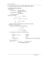
FIGURE 1.4: Classic frequency reuse for a reuse pattern of 7.
of hexagons is used to cover the entire service area. This theoretical coverage pattern in which
individual geographic areas are called cells is the origination of the term cellular [5].
To ensure a minimum distance between co-frequency cells, only certain frequency reuse
patterns are possible. Specifically, Q = i
2
+ij + j
2
for any positive integers i and j [6]. With
such patterns, it can be shown that the minimum distance between co-frequency cells is D =
√
3Qd
r
where d
r
is the cell radius [6]. This distance along with the maximum interference
tolerable determines the allowable reuse factor.
The reuse of channels means that co-channel interference is received by each receiver
in the system. The reuse pattern used depends on the minimum signal-to-interference ratio
(SIR) that can be tolerated. The SIR experienced in a system depends on the geography of the
area, the building size and density, and other environmental factors as well as the reuse pattern.
However, for the sake of discussion, let us assume that the environment is uniform, all cells
have the same size, and the transmit power decays with d
κ
where d is the distance from the
transmitter to the receiver and κ is termed the exponential path loss factor. It can be shown that
P1: IML/FFX P2: IML/FFX QC: IML/FFX T1: IML
MOBK023-01 MOBK023-Buehrer.cls September 28, 2006 15:54
MULTIUSER COMMUNICATIONS 11
six cells are always in the first tier of co-channel cells as seen in Figure 1.4. If the interference
from the first tier dominates the interference, the SIR experienced can be calculated as
SIR =
P
r
6
k=1
I
k
(1.14)
where P
r
is the desired received signal power and I
k
is the received signal power from the kth
co-channel interferer. The worst SIR on the downlink will occur when the mobile is at the cell
edge, i.e., d = d
r
. It can be shown that the uplink (the link from the mobile to the base station)
and downlink (the link from the base station to the mobile) provide similar results, so we will
look only at the downlink. Thus, if P
t
is the transmit power at each base station, the SIR is
SIR =
P
t
d
κ
r
6
k=1
P
t
D
κ
k
=
d
−κ
r
6D
−κ
=
d
−κ
r
6
√
3Qd
r
−κ
=
√
3Q
κ
6
(1.15)
where D
k
is the distance of the kth interfering base station to the mobile of interest and we
use the approximation that D
k
≈ D, ∀k. Thus, we can see that an increase in Q provides an
improvement in SIR. However, for a fixed number of cells, increasing Q decreases the number
of channels available per cell. Thus, a trade-off exists between the required SIR and spectral
efficiency as shown in the following examples.
Example 1.3. Assuming a path loss factor of κ = 4, determine the maximum number of
channels per cell if there are 450 total channels available and the required SIR is 18dB. Does
the answer change if you include both the first and the second tier of co-channel interferers?
Solution: From (1.15), we have
10
1.8
≤
√
3Q
4
6
(1.16)
Rearranging, we have
Q ≥
√
6 ∗ 10
1.8
3
= 6.48 (1.17)
P1: IML/FFX P2: IML/FFX QC: IML/FFX T1: IML
MOBK023-01 MOBK023-Buehrer.cls September 28, 2006 15:54
12 CODE DIVISION MULTIPLE ACCESS (CDMA)
The smallest valid value of Q greater than 6.48 is then Q = 7
(
i = 2, j = 1
)
. Thus, the maxi-
mum number of allowable channels per cell is
K =
450
7
= 64 (1.18)
Now, if we include the second tier of interferers, we have
SIR =
P
t
d
κ
r
6
k=1
P
t
D
κ
k
+
12
k=7
P
t
D
κ
k
(1.19)
It can be shown that D
7
= D
8
=···=D
12
= 2D. Thus, we have
SIR =
d
−κ
r
6
√
3Qd
r
−κ
+ 6
2
√
3Qd
r
−κ
=
√
3Q
κ
6 + 6/2
κ
(1.20)
which leads to
Q =
6 + 6/2
4
∗ 10
1.8
3
= 6.68 (1.21)
Clearly, including the second tier of interferers makes no significant difference, and we are
justified in ignoring it.
Frequency reuse is heavily dependent on propagation conditions as well as the desired
SIR as we can see in the following example.
Example 1.4. Repeat Example 1.3 if the path loss factor is κ = 3.
Solution: Repeating the analysis from Example 1.3 with κ = 3, we have
Q =
6 ∗ 10
1.8
2/3
3
= 17.4 (1.22)
The smallest valid value of Q greater than 17.4 is Q = 19 (i = 3, j = 2), and the maximum
number of channels per cell is K = 23. Thus, we see that while a larger path loss factor means
that more power is required to cover a particular area (i.e., there is more path loss at a fixed
P1: IML/FFX P2: IML/FFX QC: IML/FFX T1: IML
MOBK023-01 MOBK023-Buehrer.cls September 28, 2006 15:54
MULTIUSER COMMUNICATIONS 13
distance), a larger path loss factor actually benefits capacity in a multi-cell scenario since greater
isolation between cells is experienced.
The previous example showed that the efficiency of frequency reuse improves as the
propagation conditions worsen. In the next example, we show that the efficiency is also heavily
dependent on the desired SIR. Thus, if the system can tolerate lower values of SIR, the overall
system efficiency can be improved.
Example 1.5. Repeat Example 1.3 if an SIR of 12dB can be tolerated.
Solution: If an SIR of 12dB can be supported, we have (assuming κ = 4),
Q =
√
6 ∗ 10
1.2
3
= 3.25 (1.23)
The smallest allowable valueof Q greater than 3.25 is Q = 4, which provides K = 450/4 = 112
channels per cell. Thus, we clearly see that if we can tolerate lower SIR, we can increase our
capacity (i.e., the number of channels per cell).
It shouldbenoted thatfrequency reuseisclassically associated withFDMA.Theoretically,
there is no reason why pure TDMA cannot also employ reuse, although, practically speaking,
synchronization across multiple cells would pose a significant practical challenge. If systems
employ some combination of FDMA and TDMA, frequency bands can be divided according
to cells and reused as is done in second generation cellular systems based on the standards
IS-136 and Global System for Mobile Communications (GSM) [7]. CDMA, however, does
not typically employ reuse patterns. In fact, the use of universal frequency reuse (i.e., a reuse
pattern of 1) is a significant advantage of CDMA as we will discuss in detail in Chapter 3. To
demonstrate the difference between the interference statistics of FDMA and CDMA systems,
consider a TDMA/FDMA system with a reuse factor of Q = 7. As mentioned previously, the
average path loss with distance in a wireless system can be written as
PL∝ d
κ
(1.24)
However, because of terrain and various buildings in the environment, path loss versus
distance is typically found to be a log-normal random variable where the mean path loss is given
as in (1.24) and the standard deviation is between 6 and 10dB [7]. This variation is termed
shadowing. Thus, the SIR experienced on a particular link is a random variable depending on
the location of the various mobiles and the shadowing experienced by each. Specifically, the
P1: IML/FFX P2: IML/FFX QC: IML/FFX T1: IML
MOBK023-01 MOBK023-Buehrer.cls September 28, 2006 15:54
14 CODE DIVISION MULTIPLE ACCESS (CDMA)
SIR including log-normal shadowing can be written as
SIR =
P
r
6
k=1
I
k
(1.25)
where P
r
and I
k
are log-normal random variables. If we assume that the system uses power
control such that every uplink signal is received at its base station with the same power P, the
SIR for an FDMA system can be rewritten as
SIR =
P
6
k=1
P
d
k
D
k
κ
10
(
l
k
−l
k
)
/10
=
1
6
k=1
d
k
D
k
κ
10
(
l
k
−l
k
)
/10
(1.26)
where d
k
and D
k
are the distances from the kth co-channel interferer to the base station that it
is communicating with and the base station of interest, respectively, and l
k
and l
k
are the log-
normal shadowing factors from the kth co-channel interferer to its base station and the base
station of interest, respectively. On the other hand, with power control, the SIR for a CDMA
system can be written as
SIR =
N
(
K − 1
)
+
6K
k=1
f
d
k
D
k
κ
10
(
l
k
−l
k
)
/10
(1.27)
where N is the spreading gain (i.e., the ratio of the bandwidth to the data rate), K is the number
of users per cell, and f
(
x
)
is a function that guarantees that users are associated with the base
station having the smallest path loss. That is,
f
(
x
)
=
x 0 ≤ x ≤ 1
0 otherwise
(1.28)
The details of the CDMA SIR equation will be derived in Chapter 3. For now, we simply
use (1.27) to compare the SIR statistics for the two cases. Note that for CDMA systems, Q = 1
and thus D
k
=
√
3d
r
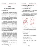
. A set of 10,000 random scenarios was simulated for uniformly distributed
users, and the empirical cumulative distribution functions (CDFs) are plotted in Figure 1.5
where the number of users K in the CDMA system was adjusted to achieve the same average
SIR. We can see that for the same average SIR, the distributions are very different. Specifically,
P1: IML/FFX P2: IML/FFX QC: IML/FFX T1: IML
MOBK023-01 MOBK023-Buehrer.cls September 28, 2006 15:54
MULTIUSER COMMUNICATIONS 15
0 5 10 15 20 25 30 35 40 45 50
0
0.1
0.2
0.3
0.4
0.5
0.6
0.7
0.8
0.9
1
SIR
Probability that
SIR
> abcissa
TDMA
CDMA
FIGURE 1.5: Empirical CDFs of SIR for FDMA and CDMA systems (both normalized to give an
average SIR of 12dB).
the CDMA system exhibits very little spread in the SIR value compared to the FDMA system.
This can be seen from the steep slope of the CDMA CDF plot. Since communication system
performance depends on the tails of the SIR (or signal-to-noise ratio, SNR) distribution, the
heavy tails of the SIR distribution in the FDMA case mean that the average SIR must be
significantly higher to achieve the same 90% value. We will examine this more thoroughly in
Chapter 3.
1.2 CONTENTION-BASED MEDIUM ACCESS CONTROL
Contention-free multiple access techniques are efficient provided that traffic is relatively con-
tinuous. If traffic is bursty, contention-free systems waste channels by dedicating them to a
single transmit/receive pair. Instead, systems with bursty traffic typically use contention-based
multiple access schemes. In contention-based schemes, the entire resource is dedicated to a
single channel and all users must contend to use the channel when they need to transmit.
P1: IML/FFX P2: IML/FFX QC: IML/FFX T1: IML
MOBK023-01 MOBK023-Buehrer.cls September 28, 2006 15:54
16 CODE DIVISION MULTIPLE ACCESS (CDMA)
1.2.1 ALOHA
The most common contention-based methods are random access methods. The first random
access method was developed by Abramson and is known as ALOHA [8,9]. In this technique,
users attempt to access the channel whenever they have data to transmit. If two users transmit
at the same time (or within a packet time), a collision occurs. When the receiver fails to
acknowledge receipt of the transmission, the transmitter realizes that a collision has occurred
and retransmits the packet. However, if the two transmitters whose packets collided both
retransmitted as soon as they realized that a collision occurred, another collision would occur.
Thus, the keyto the random access scheme is that each transmitter waits a random period before
retransmitting. This random back-off period decreases the probability of a second collision as
seen in Figure 1.6.
While this technique is a useful means of allocating the channel when traffic is random
and infrequent, it is inefficient. Specifically, the throughput of the ALOHA protocol can be
shown to be
S = λe
−2λ
(1.29)
where λ is the arrival rate of packets per packet time. The throughput is plotted in Figure
1.7. An improvement in throughput can be realized if transmissions are synchronized so that
the probability of collision is reduced by a factor of 2. This is termed Slotted ALOHA and the
resulting throughput is also shown in Figure 1.7. We can see that by adding the additional
structure to the random access, we can double the peak throughput. However, this requires
network-wide synchronization, which can be difficult to achieve in practice.
1.2.2 Carrier Sense Multiple Access and Carrier Sense Multiple
Access/Collision Avoidance
The main drawback to ALOHA and Slotted ALOHA is that transmitters blindly transmit
without attempting to determine if the channel is in use. Carrier sense multiple access (CSMA)
and carrier sense multiple access/collision avoidance (CSMA/CA) are both contention-based
Random wait
Random wait
Node 1
packet
Node 2
packet
Node 3
packet
Node 3
packet
Node 2
packet
Collision
Retransmission
Retransmission
FIGURE 1.6: Illustration of the ALOHA random access protocol.
P1: IML/FFX P2: IML/FFX QC: IML/FFX T1: IML
MOBK023-01 MOBK023-Buehrer.cls September 28, 2006 15:54
MULTIUSER COMMUNICATIONS 17
0 1 2 3 4 5 6 7
0
0.05
0.1
0.15
0.2
0.25
0.3
0.35
0.4
Offered load
Throughput
ALOHA
Slotted ALOHA
FIGURE 1.7: Network throughput for ALOHA and Slotted ALOHA.
medium access control (MAC) protocols that attempt to overcome this drawback. A node with a
packet to transmit first senses the channel to check for an ongoing transmission—hence the term
carrier sense (CS). If the node senses that the medium is free, it transmits its packet immediately.
If it senses the medium is busy, it either waits until it is free and transmits (persistent-1 CSMA)
or waits until it is free and then sets a random timer, waits for the timer to expire, and (if it
has sensed no additional transmissions) then transmits (non-persistent CSMA). CSMA can also
be slotted or unslotted just as ALOHA. The throughput of CSMA is plotted in Figure 1.8.
Note that persistent-1 CSMA can provide better throughput than ALOHA and non-persistent
CSMA at low loading levels. However, at high system loading factors, non-persistent CSMA
provides far superior performance.
The previously described contention-based wireless networks suffer from the hidden
node/exposed node problem. The hidden node problem is more severe than is the exposed node
problem in most scenarios. The hidden node problem is demonstrated in Figure 1.9. The hidden
node (Node 3) cannot sense the ongoing communication between the sender (Node 1) and the
receiver (Node 2), senses the channel as idle, and proceeds with transmission of its packet to the
P1: IML/FFX P2: IML/FFX QC: IML/FFX T1: IML
MOBK023-01 MOBK023-Buehrer.cls September 28, 2006 15:54
18 CODE DIVISION MULTIPLE ACCESS (CDMA)
0 1 2 3 4 5 6 7 8 9 10
0
0.1
0.2
0.3
0.4
0.5
0.6
0.7
0.8
0.9
Offered load
Throughput
ALOHA
Slotted ALOHA
Non-persistent CSMA
Slotted non-persistent CSMA
Slotted persistent-1 CSMA
FIGURE 1.8: System throughput for CSMA compared with ALOHA.
1
2
3
Range of terminal 1
Range of terminal 2
FIGURE 1.9: Illustration of the hidden node problem in CSMA.
P1: IML/FFX P2: IML/FFX QC: IML/FFX T1: IML
MOBK023-01 MOBK023-Buehrer.cls September 28, 2006 15:54
MULTIUSER COMMUNICATIONS 19
receiver, causing a collision at the receiver. The exposed node problem occurs when the exposed
node senses the channel as busy because it can listen to the sender’s ongoing communication
with the receiver. The exposed node can still communicate with its intended receiver even if it
senses a carrier because the proximity of a transmission to the transmitter does not necessarily
indicate the proximity of a transmission to the receiver. Thus, it is possible that even though the
transmitter suppressed transmission, it could have successfully communicated with its intended
receiver. Both hidden and exposed node problems lead to a reduction in aggregate throughput.
The CSMA protocol has no means to avoid the hidden node/exposed node problems.
To overcome the problem of the hidden and exposed terminals, the MACA (Multiple
Access Collision Avoidance) protocol was proposed [10]. This protocol gets rid of the carrier
sense in the CSMA protocol and instead uses a different algorithm for collision avoidance,
hence the name MACA. Specifically, it relies on an RTS/CTS (request-to-send/clear-to-send)
handshake to avoid collisions at the receiver. When Node A wishes to transmit to Node B, it
first sends an RTS to Node B containing the length of the proposed data transmission. If the
node hears the RTS and is not deferring, it replies with a CTS packet. When Node A hears the
CTS, it immediately sends its data. Any node that hears the RTS defers all transmissions until
after the expected reception of the CTS message. All nodes that hear the CTS message defer
until the end of the data transmission. Thus, all nodes (and only those nodes) that are capable
of interfering with the CTS or the data transmission avoid transmitting during the appropriate
intervals.
The CSMA/CA protocol combines the carrier sensemechanismwithcollisionavoidance.
It solves thehiddennode problembyusing the RTS/CTSmechanism. This issometimestermed
a virtual carrier sense. Before making an attempt to send any data after the back-off interval
associated with the collision avoidance has elapsed, the node again senses the channel. This
technique helps resolve contention and reduces collision probability under high load conditions.
1.2.3 Other Random Access Methods
Most of the protocols discussed in the previous section require a particular node to listen for
the carrier. It should be noted that carrier sense prevents collisions from happening at the
transmitter, but most collisions occur at the receiver (the hidden node/exposed node problem
as described previously). The lack of a carrier does not always indicate that it is safe to transmit
(i.e., the hiddennode problem), and the presence of a carrier does notalways mean thatthe node
should not transmit (i.e., exposed node problem). So carrier sense is not always an appropriate
indication of the current channel utilization.
Bhargavan slightly modified the MACA protocol and proposed a new multiple access
protocol termed MACAW (Multiple Access Collision Avoidance Protocol for Wireless LANs)
[11]. This protocol proposed the addition of an ACK for every DATA packet sent. (This is now
P1: IML/FFX P2: IML/FFX QC: IML/FFX T1: IML
MOBK023-01 MOBK023-Buehrer.cls September 28, 2006 15:54
20 CODE DIVISION MULTIPLE ACCESS (CDMA)
used in the 802.11 standards.) The ACK allows for quick determination of a lost packet. If an
ACK is not received within a defined time frame, the transmitter assumes that the packet was
lost and schedules a retransmission of the packet. This dramatically improves system throughput
in noisy channels [11].
The protocol also adds a data-sending (DS) packet after the CTS message. The exchange
sequence between the transmitter and the receiver thus looks like RTS–CTS–DS–DATA–ACK
where the DS stands for the data-sending frame, which tellsthenodes that a successful exchange
of RTS/CTShasoccured. This preventsanexposednode fromattemptingto transmit anRTS to
a sender near toit, which would lead to largeback-offs because the sender isalready transmitting
data to another node and would not respond to the exposed node’s request.
Another variation of the MACA protocol is the MACA/BI (MACA—By Invitation)
protocol first proposed by Talucci [12]. In this protocol, an RTS frame is not sent from an
intended transmitter to the receiver. Instead, this is a receiver-initiated protocol in which the
receiver determines when a sender is likely to send a packet (either by relying on the packet
arrival rate or bythesendertelling the receiver in the previous packet about a backlog of packets).
The receiver then initiates (prepares the floor for transmission) a call by sending a CTS to the
sender. The sender, after receiving the CTS, starts transmitting data to the receiver.
Tobagi also addressed the hidden node problem [13] by using a busy tone to indicate the
ongoing transmission and thus preventing any other node from initiating another transmission.
All the nodes monitor the busy tone to determine the availability of the channel. The proposed
protocol does not use RTS and CTS for collision avoidance and depends on centralized access
to avoid collisions. (By using a centralized access topology, channel access time is allocated to
each user such that two nodes do not contend for the same channel time.) Attempts along
similar lines were made [14,15] to avoid the hidden node problem. They also use the busy tone
technique to avoid collisions.
The FAMA(Floor AcquisitionMultipleAccess) scheme was proposed[16]inwhich each
node is required to acquire the channel before it may initiate the transmission. The node uses
both carrier sensing and RTS/CTS to acquire the floor. Once the floor is acquired, the node can
successfully transmit data. Fullmer studied FAMA/NPS (FAMA non-persistent packet sens-
ing) and showed that packet sensing schemes alone could not solve the hidden node/exposed
node problem [16]. FAMA was extended to FAMA/NCS (FAMA non-persistent carrier
sensing), which uses a CTS dominance mechanism (longer CTS packets). If the node has
begun transmission of the CTS packet and, at the same time, an RTS packet is sent, the
node transmitting the RTS packet hears the CTS packet and refrains from accessing the
channel.
Haas proposed dual busy tone multiple access (DBTMA) [17]. The protocol uses two
out-of-band tones along with the RTS/CTS handshake for informing neighbors about an
P1: IML/FFX P2: IML/FFX QC: IML/FFX T1: IML
MOBK023-01 MOBK023-Buehrer.cls September 28, 2006 15:54
MULTIUSER COMMUNICATIONS 21
on-going transmission. The protocol resolves the hidden node/exposed node problem com-
pletely. A brief description of the algorithm is as follows. Once an RTS packet is transmitted,
the BTt (busy tone—transmitter) signal is set to prevent the RTS from getting corrupted. On
hearing the BTt tone, the other transmitters would refrain from sending an RTS packet and
back-off. At the end of the RTS transmission, the transmitter turns off the BTt tone and waits
for the CTS packet from the receiver. Once the RTS packet is received, the receiver responds
with the CTS packet and sets the BTr (busy tone—receiver) signal. Any transmitter in the
vicinity of the receiver hears the tone and does not transmit while the tone is set. It might
happen that two simultaneous RTS packets are sent, which corrupts the RTS signal. In this
case, the receiver would not understand the command and would not respond. Both the trans-
mitters would individually time out and repeat the above procedure before again sending the
RTS packet. This prevents corruption of the data. This algorithm also solves the hidden ter-
minal/exposed terminal problem, as the hidden nodes can reply to RTS requests by setting
their busy tones and the exposed node can initiate a transmission because it no longer needs to
listen to the shared medium. Although the DBTMA scheme solves the hidden/exposed node
problem, it requires two additional channels for setting the BTr and the BTt signals, which is
a significant overhead in the already crowded spectrum allocated for WLANs.
The 802.11 MAC layer [18] is based on the CSMA/CA + ACK protocol for uni-
cast frames and the CSMA/CD (carrier sense multiple access/collision detection) protocol for
broadcast frames. It also deploys a virtual carrier sense mechanism (using RTS/CTS) to avoid
a station from transmitting when two nodes are already communicating.
1.3 MULTIPLE ACCESS WITH SPREAD SPECTRUM
Theoretically, systems that utilize spread spectrum waveforms could use any of the multiple
access schemes described earlier. Specifically, if the application lent itself to contention-free
multiple access, a system could combine a spread spectrum physical layer with TDMA, FDMA,
or CDMA. However, spread spectrum signals have a bandwidth N times larger than the data
rate. The use of TDMA or FDMA would require N times as much bandwidth for the entire
system. However, since in CDMA all signals can occupy the same spectrum, no additional
bandwidth is needed to add more users. Thus, while spread spectrum signals are inefficient in
terms of bandwidth, a CDMA system may have good bandwidth efficiency.
For contention-based multiple access, the previously-mentioned schemes (or adaptations
thereof) can be used with spread spectrum waveforms. For example, some forms of 802.11
use direct sequence spread spectrum waveforms but use CSMA/CA for multiple access. We
will discuss specific modifications of contention-based MAC protocols for spread spectrum in
Chapter 4.
P1: IML/FFX P2: IML/FFX QC: IML/FFX T1: IML
MOBK023-01 MOBK023-Buehrer.cls September 28, 2006 15:54
22 CODE DIVISION MULTIPLE ACCESS (CDMA)
1.4 SUMMARY
In this chapter, we have investigated basic concepts in multiuser communications. Specifically,
we have discussed fundamental techniques for allowing multiple pairs of users to communi-
cate using the same medium. These techniques are typically divided into contention-free and
contention-based techniques. Spread spectrum systems can use either type depending on the
type of traffic in the system. Of primary importance in this book are CDMA techniques specifi-
cally for contention-free systems. In thefollowing chapters, we will describe CDMA techniques
more thoroughly for contention-free access as well as contention-based access schemes utilizing
spread spectrum waveforms.
P1: IML/FFX P2: IML
MOBK023-02 MOBK023-Buehrer.cls September 28, 2006 15:54
23
CHAPTER 2
Spread Spectrum Techniques for
Code Division Multiple Access
In the previous chapter, we reviewed the basic concepts of multiuser communications and the
multiple access techniques used to allow multiple users to communicate. In this chapter, we will
focus on the major forms of spread spectrum communication and their application to CDMA.
CDMA is based on spread spectrum techniques that originated in military communications.
In CDMA, channels are defined by spreading waveforms or the spreading codes that underlie
those waveforms. There are several types of spread spectrum, and thus there are several types
of CDMA. We will focus on the two basic forms of CDMA: direct sequence CDMA (DS-
CDMA) and frequency-hopped CDMA (FH-CDMA). We will also briefly mention a third type
of CDMA termed time-hopped CDMA that is currently receiving attention for its application
to ultra-wideband (UWB) systems.
2.1 FORMS OF CODE DIVISION MULTIPLE ACCESS
CDMA is also known as spread spectrum multiple access or SSMA because the use of spread
spectrum waveforms is fundamental to CDMA.
1
Spread spectrum can be defined as any mod-
ulation technique that uses a bandwidth that is well beyond what is necessary for the data
rate being transmitted and uses a pseudo-random signal to obtain the increased bandwidth.
The latter factor distinguishes spread spectrum techniques from standard communication tech-
niques such as frequency modulation (FM) and high-order orthogonal signaling, which may
also require high bandwidth compared to the information rate. There are two main reasons why
spread spectrum waveforms were traditionally used: low probability of intercept and resistance
to jamming [1,19]. These two properties are a direct result of both the excess bandwidth used
by spread spectrum waveforms and the resulting low power spectral density (PSD) and can also
be directly exploited to provide multiple access. In multiple access systems, we are concerned
1
Some make a distinction between CDMA and SSMA in that CDMA specifically designs its spreading waveforms
to have low cross-correlation properties, whereas SSMA systems have independent codes that may also have low
cross-correlation [1]. We do not make such a distinction here.
P1: IML/FFX P2: IML
MOBK023-02 MOBK023-Buehrer.cls September 28, 2006 15:54
24 CODE DIVISION MULTIPLE ACCESS (CDMA)
with the interference from and to other spread spectrum waveforms rather than with hostile
narrowband receivers or jamming signals.
Therearetwobasic spread spectrum techniques:direct sequence spreadspectrum(DS/SS)
and frequency-hopped spread spectrum (FH/SS) [1, 19, 20]. These two techniques can be
used for multiple access and are commonly termed DS-CDMA and FH-CDMA. We will
examine both these techniques in the following sections (Sections 2.2 and 2.3) and discuss
their performance in AWGN and fading channels as well as their multiple access capabilities.
Both techniques rely on spreading waveforms to accomplish pseudo-random spreading. A key
to CDMA is defining multiple spreading waveforms with low cross-correlation properties to
allow multiple users to share the spectrum efficiently. A third technique that has gained more
attention in recent years is termed time-hopped spread spectrum. This will be discussed briefly
in Section 2.4. The link performance and multiple access capabilities of DS-CDMA will be
discussed in Sections 2.5 and 2.6, respectively, and the link performance and multiple access
capabilities of FH-CDMA will be discussed in Sections 2.7 and 2.8.
2.2 DIRECT SEQUENCE CODE DIVISION MULTIPLE ACCESS
DS/SS is perhaps the most common form of spread spectrum in use today. DS/SS accomplishes
bandwidth spreading through the use of a high rate symbol sequence (termed a chip sequence)
that directly multiplies the information symbol stream. Since the chip sequence has a rate much
higher than the data rate, the bandwidth is increased. The simplest form of DS/SS uses binary
phase shift keying (BPSK) modulation with BPSK spreading and is illustrated in Figure 2.1.
Note that this is equivalent to a standard BPSK system with a matched filter receiver with the
X
X
r(t)
T
dt
0
Z
Z < 0
Z > 0
b(t)
a(t)
2Pcos(ω
c
t) carrier
s(t)
X
X
Data signal
Spreading signal
Transmitter
Receiver
These two
additional
sections
account for
spreading and
despreading.
X
a(t)
cos(ω
c
t)
b = +1
^
b =
-
1
^
b
^
∫
If we remove the
portions in the dashed
box, we have standard
BPSK modulation.
FIGURE 2.1: Transmitter and receiver block diagram for BPSK spreading and BPSK modulation.
P1: IML/FFX P2: IML
MOBK023-02 MOBK023-Buehrer.cls September 28, 2006 15:54
SPREAD SPECTRUM TECHNIQUES FOR CODE DIVISION MULTIPLE ACCESS 25
addition of the spreading and despreading process. The receiver is equivalent to a matched filter
for a DS/SS signal provided that square pulses are used. If pulse shaping is employed, the simple
integrator should be replaced by a filter that is matched to the pulse shape used. If the pulse
shape is incorporated at the chip level, it should also be incorporated into a(t). The transmit
signal can be represented by
s (t) =
√
2Pa(t) cos
(
2π f
c
t +θ
d
(
t
))
=
√
2Pa(t)b(t) cos
(
2π f
c
t
)
(2.1)
where θ
d
(t) is the binary phase shift due to the information sequence, b(t) =
∞
i=−∞
b
i
p
b
(t −
iT
b
) is the information signal where b
i
∈
{
+1, −1
}
represent the information bits, each bit has
duration T
b
, p
b
(t) is the unit energy pulse shape used for the information waveform (assumed
to be rectangular), a(t) =
∞
i=−∞
a
i
p
c
(t −iT
c
) is the spreading signal where each symbol a
i
(usually called a chip) has duration T
c
= T
b
/N, f
c
is the center frequency of the transmit signal,
P is the power of the signal, and N is the bandwidth expansion factor, sometimes also called
the spreading gain. Example waveforms for the case of rectangular pulses are given in Figure 2.2.
t
−1
+1
T
b
2T
b
3T
b
0
t
−1
+1
0
T
c
Data signal
Spreading signal
N = T
b
/T
c
= bandwidth expansion = processing gain
b(t)
a(t)
T
b
2T
b
3T
b
FIGURE 2.2: Example data and chip sequences for DS/SS with BPSK information and BPSK
spreading.
P1: IML/FFX P2: IML
MOBK023-02 MOBK023-Buehrer.cls September 28, 2006 15:54
26 CODE DIVISION MULTIPLE ACCESS (CDMA)
It can be seen that the chip rate is N times that of the bit rate, resulting in a signal whose
bandwidth is much larger than necessary for transmission of the information. Specifically, as we
will show later, the bandwidth is commensurate with the chip rate or N times what a traditional
BPSK signal bandwidth would be.
At the receiver, the opposite operations are performed. Specifically, the signal is first
down-converted to baseband.
2
After down-conversion, the signal is despread and passed to a
standard BPSK detector. This process can be envisioned in two ways. First, we can view the
spreading/despreading operations as transparent additions to a standard BPSK transmit/receive
pair. The spreading is applied after BPSK symbol creation and despreading occurs before the
BPSK detector. Second, we can view DS/SS as a BPSK modulation scheme where the “pulse”
is the spreading waveform. Thus, at the receiver the despreading operation can be viewed as
part of a correlator version of a matched filter receiver.
At the receiver, the received signal can be modeled as
r(t) = s(t) +n(t)
=
√
2Pa(t)b(t) cos
(
2π f
c
t
)
+ n(t) (2.2)
wheren(t) isbandpassAWGNandwheretherandom phaseoffsetdue topropagationisassumed
to be zero for simplicity. The maximum likelihood receiver then calculates the decision statistic
as
Z =
1
T
b
T
b
0
r(t)a(t) cos
(
2π f
c
t
)
dt
=
1
T
b
T
b
0
√
2Pa(t)b(t) cos
(
2π f
c
t
)
a(t) cos
(
2π f
c
t
)
dt
+
1
T
b
T
b
0
n
(
t
)
a(t) cos
(
2π f
c
t
)
dt
=
1
T
b
T
b
0
√
2Pa
2
(t)b(t) cos
2
(
2π f
c
t
)
dt + n (2.3)
where we have assumed perfect phase coherence, bit timing, and chip timing at the receiver
and where n is a noise sample at the output of the matched filter. Now, in BPSK spreading, the
spreading signal a(t) can be modeled as
a(t) =
∞
i=−∞
a
i
p
c
(
t −iT
c
)
(2.4)
2
Despreading can also be done at IF although baseband is currently more common.
P1: IML/FFX P2: IML
MOBK023-02 MOBK023-Buehrer.cls September 28, 2006 15:54
SPREAD SPECTRUM TECHNIQUES FOR CODE DIVISION MULTIPLE ACCESS 27
where a
i
∈
{
+1, −1
}
is the spreading sequence and p
c
(t) is the chip pulse shape, assumed to be
rectangular for this discussion. We will discuss the properties of the spreading sequence later,
but for now we will assume that the chip values are random and independent. It can be readily
discerned that a
2
(t) = 1. Further, ignoring the double frequency term in (2.3), the decision
statistic becomes
Z =
√
2P
2
b
0
+ n (2.5)
where we have assumed that b
0
is the bit value corresponding to the interval of interest, p
b
(t)
is a rectangular pulse of duration T
b
, and n is due to AWGN and will be analyzed later. Thus,
we can see that we obtain a decision variable that comprises the original bit along with a noise
term, just as in standard BPSK. We will analyze the performance of this scheme shortly.
2.2.1 Power Spectral Density of Direct Sequence Spread Spectrum
The Power Spectral Density (PSD) of DS/SS depends on the modulation scheme used as well
as the pulse shape used. To this point, we have assumed the use of square pulses for convenience.
Based on the Wiener–Khintchine theorem, the PSD [21] of a random process is the Fourier
transform of the autocorrelation function of that process. For a PAM signal of the form
x(t) =
∞
i=−∞
a
i
p(t −iT
s
) (2.6)
where a
i
are arbitrary pulse amplitudes and p(t) is the pulse shape, the power spectral density
can be shown to be [22]
S
x
( f ) =
P( f )
2
T
s
∞
k=−∞
R
(a,a)
[k]e
−j2π fkT
s
(2.7)
where P( f ) is the Fourier transform of the pulse shape, R
a,a
[k] = a
i
a
i+k
is the autocorrelation
function of the data sequence, and T
s
is the symbol duration. Now, if the data is uncorrelated,
3
R
a,a
[k] =
a
2
i
k = 0
a
i
a
i+k
k = 0
=
σ
2
a
+ m
2
a
k = 0
m
2
a
k = 0
(2.8)
3
Note that this is an approximation for the DS/SS spreading waveform since the spreading code is pseudo-random
and periodic. For extremely long spreading codes, however, this approximation is very good.
P1: IML/FFX P2: IML
MOBK023-02 MOBK023-Buehrer.cls September 28, 2006 15:54
28 CODE DIVISION MULTIPLE ACCESS (CDMA)
where m
a
and σ
2
a
are the mean and variance of the data amplitude sequence, respectively.
Returning to the power spectral density, we have
S
x
( f ) =
P( f )
2
T
s
∞
k=−∞
R
a,a
[k]e
−j2π fkT
s
=
P( f )
2
T
s
σ
2
a
+ m
2
a
∞
k=−∞
e
−j2π fkT
s
=
P( f )
2
T
s
σ
2
a
+ m
2
a
∞
k=−∞
δ
f −
k
T
s
=
σ
2
a
T
s
P( f )
2
+
m
2
a
T
s
∞
k=−∞
P
k
T
s
2
δ
f −
k
T
s
(2.9)
Now for phase modulation, m
a
= 0 and σ
2
a
= 1. Further, if square pulses are assumed, P( f ) =
T
s
sinc(T
s
f ). Thus,
S
x
( f ) = T
s
sinc
2
(T
s
f ) (2.10)
Since both the spreading waveform and the data waveform have the same format, we have the
power spectral density of both. Now it remains to find the PSD of the transmitted waveform.
The complex baseband version of the transmitted signal
˜
s (t) is an ergodic random process
and the power spectral density can be found from the Fourier transform of the autocorrelation
function. Since the data and the spreading sequence are independent, the autocorrelation func-
tion of the transmit signal is the product of the autocorrelation functions of the two signals.
That is, since
˜
s (t) =
√
Pa(t)b(t) (2.11)
then
R
s,s
(τ ) = E
˜
s (t)
˜
s
∗
(t +τ)
= E
a(t)b(t)a(t + τ )b(t + τ )
= E
a(t)a(t +τ)
E
b(t)b(t +τ)
= R
a,a
(τ )R
b,b
(τ ) (2.12)
The power spectral density is then the Fourier transform of the autocorrelation function:
S
x
( f ) =
∞
−∞
S
b
(φ)S
a
( f − φ) dφ
=
∞
−∞
T
b
sinc
2
(
φT
b
)
T
c
sinc
2
([
f − φ
]
T
c
)
dφ
=
∞
−∞
T
b
sinc
2
(
φT
b
)
T
b
N
sinc
2
[
f − φ
]
T
b
N
dφ (2.13)