Cross Modulation in CDMA Mobile Phone Transceivers phần 2 ppsx
Bạn đang xem bản rút gọn của tài liệu. Xem và tải ngay bản đầy đủ của tài liệu tại đây (947.08 KB, 10 trang )
11
H
•
4/17/01
Page 11
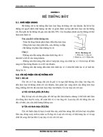
IS-95 CDMA Mobile Phone Transmitter
The IS-95 reverse link mobile transmitter is shown above. In the
numeric domain, an impulse source clocks two PN (pseudo random
noise) sequence generators that are based on IS-95. Each chip output
of the PN source has 2 samples. It is down samples to 1 sample/chip
and then upsampled to 4 samples per chip with zero insertion in order
to be compatible with the following stage IS-95 FIR filters. IS-95 defines
the impulse response of these filters with 4 samples/chip, assuming the
I and Q data inputs are an impulse stream. After the FIR filter, the Q
channel is delayed by Tchip/2 i.e. by 2 samples, for offset QPSK
modulation. The I and Q signals are converted to time domain and QAM
modulated on to a carrier at frequency “ftx” MHz.
The out-of-band noise floor is flat and very high for the IS-95
transmitter. In order reduce the out-of-band noise floor and to reduce
spectral leakage, especially into the RX channel for cross modulation
simulation, the impulse response of the IS-95 FIR filters must be
extended. This is done by cascading a raised cosine filter either in base
band or at RF, after increasing the sampling rate. The band width of the
raised cosine filter must be carefully set so that it is not too narrow to
degrade the IS-95 RHO factor and the MSE (mean square error of IS-
95 filter coefficients), and at the same time fit the TX spectral template.
Too wide a band width produces a step in the spectrum skirt (out-of-
band region has a step in the noise floor).
12
H
•
4/17/01
Page 12
Modulated RF input
1 sample output:
power in dBm
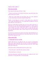
RF Power Measurement in ADS
A model for gated RF power measurement is shown above. The output of an
envelope detector is squared and integrated over the gated time (between
Tsave and Tstop). The “CHOP” block selects the gated region of the signal.
Only one power measurement sample must be read at the output port.
13
H
•
4/17/01
Page 13
Intermodulation
Intermodulation
TX specrtal regrowth
Cross Mod
Noise
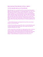
Cross Modulation simulated spectrum
The simulated spectrum at the output of the LNA is shown in the figure
above. The cross modulation noise spectrum at the output of the RX
band pass channel filter is in the region marked by the rectangle.
In the one-tone desensitization test of an IS-95 mobile phone, an
unmodulated -30 dBm (Pjam) carrier tone at an offset of 900 kHz
(Cellular) or 1.25 MHz (PCS) interferes with the received CDMA signal
at -101 dBm (Prx). Because of the CDMA transmitter open and closed
loop power control, the handset is forced to transmit the maximum
power when the received signal is close to the sensitivity level of -104
dBm. With a typical 45 dB isolation (Ltx) in the duplexer, the transmitter
leakage into the receiver LNA is -22 dBm. The unmodulated interferer
at the LNA input is about -33 dBm considering a 3 dB insertion loss
(Lrx) in the duplexer received path.
Due to the 3rd order nonlinearity of the LNA, the jammer get cross
modulated by the transmitter leakage. A part of this cross modulation
power falls in the receive channel. If the LNA ip3 or the duplexer
isolation is not large enough, the the cross modulation power in the
receive channel can significantly exceed the total thermal noise power.
14
H
•
4/17/01
Page 14
Total cross modulation noise within the 1.25 MHz receive band
Cellular band:
PCS band:
Equivalent noise figure of a 0 dB gain amplifier:
Simulated Model for Cross Modulation Noise
Based on the simulation results, a model has been derived, showing the
relationship among the LNA IP3, transmitter leakage power, the 1-tone
jammer power, and the total receive in-band cross modulation noise
power. The first and second equations above depict the models.
The receiver in-band cross modulation noise power in the PCS band is
about 2.6 dB less than in the cellular band for the same transmitter and
interferer levels, because the PCS 1-tone interferer is further away from
the receive band, compared with the cellular 1-tone interferer.
In the equations above,
Pnoise = Cross Modulation noise power in 1.23 MHz receiver pass
band.
Ptx = transmitter power at antenna (23 dBm Cellular, 15 dBm PCS), at
f
TX
.
Ltx = duplexer attenuation at f
TX
, from antenna to Receiver LNA.
PIIP3 = input 2-tone IP3 of receiver LNA.
Pjam = 1-tone jammer power (-30 dBm) at antenna, at 900 kHz
(cellular) or 1.25 MHz (PCS) offset from receive frequency f
RX
.
Lrx = duplexer insertion loss (antenna to LNA) around fRX.
If the cross modulation noise power is modeled as an equivalent noise
power of a 0 dB gain amplifier, then the last equation models the noise
figure of such an amplifier.
15
H
•
4/17/01
Page 15
• Cross modulation is only AM noise
• 3 dB less S/N degradation relative to AWGN of same power
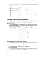
Cross Modulation Noise vs Duplexer Isolation
The variation of Pnoise versus the duplexer isolation Ltx, is plotted
above.
Comparison of Cross Modulation noise with additive White
thermal noise
A simulation was done to compare the effects of white noise and cross
modulation noise on the pilot and traffic signal to noise ratio after de-
spreading. It was found that the cross modulation power had to be
about 3 dB higher than the thermal white noise power in order to
produce the same signal to noise ratio after de-spreading. This could
be attributed to the fact that there is no phase noise associated with
cross modulation. Cross modulation is only an amplitude modulation
effect. Secondly, the in-band cross modulation noise only occupies
about half of the 1.23 MHz span, and after despreading some of its
power may go outside the relevant band. This 3 dB correction has not
been incorporated into the equations and graphs.
16
H
•
4/17/01
Page 16
•For AWGN comparison, reduce noise figure by about 3 dB
Simulated Model for Cross Modulation Noise
A variation of the equivalent Cross Modulation noise figure versus the
duplexer isolation Ltx, is plotted above for the Cellular band. Presently
duplexers have about 50 dB TX-RX isolation shown by the green
shaded region.
17
H
•
4/17/01
Page 17
Philips Semiconductors BiCMOS Process
Receiver LNA Specifications
LNA Specification
The cross modulation noise power significantly contributes to the overall
receiver noise figure if the LNA IP3 is insufficient. A dual band LNA in
the Philips Semiconductor's QUBIC-3 BiCMOS process, with the
specifications listed in TABLE 1above, can meet the IS-95 mobile test
requirements. In this table, the equivalent noise figure for the cross
modulation has been computed by including the additional 3 dB benefit
that is gained when compared with white noise. It can be seen that for
the cross modulation case, the required IP3 for the LNA, or the isolation
for the duplexer, is very high compared with the 2- tone test case.
Due to the very high IP3 requirement of the LNA in the PCS band, there
is a proposal to change the IS- 95 specifications according to which the
reverse link transmitter power should be reduced from 23 dBm to 15
dBm, for the one-tone desensitization test. If implemented, it would
amount to a major relaxation of the LNA input IP3 or the duplexer
isolation, in the PCS band.
18
H
•
4/17/01
Page 18
D
D
esign
esign
S
S
eminar
eminar
Agilent EEsof
Agilent EEsof
Customer Education
Customer Education
and Applications
and Applications
Part 2
Linearization of LNA for Improved Cross
Modulation Performance
Theoretical results and simulations on gain compression and desensitization of
the LNA are presented. Based on this, a linearization technique of the LNA is
proposed, backed with simulations. Using this linearization technique it may
be possible to considerably reduce the high IP3 requirement for the LNA, or
the high duplexer TX-RX isolation requirement, for cross modulation noise
that results from the combination of TX leakage and Jammers at the LNA
input. The advantage of this technique is that it may be possible to do the
linearization completely within the receiver LNA block itself.
19
H
•
4/17/01
Page 19
First a look at Gain Compression:
(For an ideal memory less 3rd order nonlinearity)
(definition of Gain Compression)
In general, for a memory less higher order nonlinearity:
Desensitization Analysis
Gain Compression of LNA
The above equations show the gain compression of a large signal that
has a time varying instantaneous power P
T
(t) at the LNA input. P
IIP3
is
the LNA input IP3. In the expressions for gain compression c(t) which is
time varying, memory effects and phase distortions have not been
considered.
20
H
•
4/17/01
Page 20
Desensitization d(t) is the fractional change in gain of a small
signal when a large signal appears. Mathematically,
s
J
(t) is the small signal jammer, with power P
J.
P
T
(t) is the power of the large signal
The Jammer s
J
(t) gets desensitized
by the strong TX leakage power P
T
(t)
d(t) varies in sync with P
T
(t) AM modulation of Jammer s
J
(t)
Time varying Desensitization
Desensitization
When a smaller jammer signal s
J
(t) is present along with the time varying
larger TX leakage signal that has an instantaneous power P
T
(t) at the LNA
input, the smaller signal undergoes a time varying gain change
(desensitization) that is about double that of the large signal.
The time varying desensitization of the smaller signal is basically AM
modulation, and it is another definition of cross modulation. Using this
definition, it is easier to see how the LNA can be linearized for minimizing
cross modulation.