Enhanced Radio Access Technologies for Next Generation Mobile Communication phần 9 pot
Bạn đang xem bản rút gọn của tài liệu. Xem và tải ngay bản đầy đủ của tài liệu tại đây (676.98 KB, 24 trang )
EVOLVED UTRA TECHNOLOGIES 229
domain compared to the reference symbols of the first OFDM symbol. It was
reported that by multiplexing reference signals into two OFDM symbols within
a sub-frame, low-to-high mobility environments up to, e.g., 350 km/h can be
supported without additional reference signals in the time domain.
4.1.2 Orthogonal reference signals
In E-UTRA, it should be possible to provide orthogonal reference signals between
cells of the same Node B as well as between different transmit antennas of the same
cell. Orthogonal reference signals between transmit antennas within the same cell
is e.g. needed to support downlink transmit diversity and MIMO transmission.
(1) Orthogonal reference signals for different transmission antennas
Orthogonal reference signals for different transmit antennas of the same cell/beam is
established by means of FDM, possibly in combination with TDM. Thus, reference-
signal multiplexing with different antenna-specific frequency (or time) shifts is used
for each antenna. The main reason for relying on FDM/TDM-based orthogonality
between transmit antennas of the same cell/beam is that it provides more accurate
orthogonality compared to CDM-based orthogonality since no inter-code inter-
ference occurs in a frequency-selective fading channel. A high level of orthogonal
accuracy is necessary to separate composite streams from different antennas in
MIMO multiplexing and MIMO diversity schemes.
(2) Orthogonal reference signals for different cells in the same Node B
CDM-based reference-signal orthogonality is used between different cells/beams
belonging to the same Node B in order to suppress the mutual interference particu-
larly near the cell boundary. The merit of CDM-based orthogonality, compared to
FDM-based orthogonality, between cells of the same Node B is a better tracking
ability for the channel estimation, particularly UEs far from sector borders, since the
density of the CDM-based orthogonal reference symbols in the frequency domain
is higher than in case of FDM-based orthogonality.
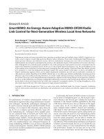
Figure 6 shows the principle of the intra-Node B orthogonal reference signal
employing the combination of a Node B-specific scrambling code and cell-specific
orthogonal sequence in the same Node B. As shown in Figure 6, we employ the
same scrambled code among all cells belonging to the same Node B unlike in
the WCDMA scrambled code assignment. Furthermore, a cell-specific orthogonal
sequence is applied in order to distinguish cells (typically three or six) within
the same Node B. Therefore, the resultant cell-specific scrambled code for the
reference signal, p
nm
(n is the cell belonging to the same Node B and mis the index
for the reference symbols), is generated through the combination, i.e., multipli-
cation, of a Node B-specific scrambled code and cell-specific orthogonal sequence
represented as
(2) p
nm
=c
m
·s
nm mod SF
In this equation, c
m
denotes the Node B-specific scrambled code, and s
nm
is the
orthogonal sequence with the spreading factor of SF employed in the n-th cell.
230 CHAPTER 7
Node B-specific
scrambling code
Sector-specific
orthogonal
sequence
Sector #1
Sector #2
Sector #3
Mutuall
y
ortho
g
onal sequence
Spreading factor
Frequency
c1 c2 c3 c4 c5 c6 c7 c8 c9
c10 c11 c12
s1,1 s1,2 s1,3
s2,1 s2,2 s2,3
s3,1 s3,2 s3,3
s1,1 s1,2 s1,3
s2,1 s2,2 s2,3
s3,1 s3,2 s3,3
s1,1 s1,2
s1,3
s2,1 s2,2 s2,3
s3,1 s3,2
s3,3
s1,1 s1,2 s1,3
s2,1 s2,2 s2,3
s3,1 s3,2 s3,3
Figure 6. Principle of intra-Node B orthogonal reference signal structure
The cell-specific orthogonal sequence is generated by a Walsh-Hadamard sequence
or phase rotation sequence. Here, we assume a cell-specific orthogonal sequence
generated by phase rotation as indicated in the following equation assuming
N sectors (SF = N in the same Node B.
(3) s
nm
=exp
j
2n
N
m
Thus, in the three-cell configuration at each Node B, the phase rotation of 0, 2/3,
and 4/3 is added to Sectored beams 1, 2, and 3, respectively. Using the orthogonal
reference signal in Figure 6, intra-Node B orthogonality in the channel estimate is
achieved by despreading CDM based reference symbols in the frequency or time
domain. Note that the channel estimate at each sub-carrier is directly used without
despreading for the UE without intra-Node B macro-diversity.
4.2 Broadcast Channel (BCH)
The broadcast channel (BCH) is used to broadcast system and cell-specific control
information over the entire cell area. The broadcast control information includes
information related to connection setup, cell selection, and re-selection, etc
4.2.1 Broadcast Control Information
Broadcast control information can be categorized into cell-specific information,
Node B-specific information, and system-specific information. Furthermore, another
level of categorization is primary information, which is necessary to be immediately
available to UE after cell search and initial acquisition, and non-primary information.
Table 2 lists different kinds of broadcast control information together with the
categorization according to above.
EVOLVED UTRA TECHNOLOGIES 231
Table 2. Broad cast Control Information
System control information elements Classification (Area scope) Primary or not
SFN (System Frame Number) Node B specific or cell specific Primary
PLMN (Public Land Mobile
Network) identity
Node B specific or cell specific Primary
Overall transmission bandwidth Node B specific Primary
Number of transmit antennas Node B specific or cell specific Primary
Scheduling and update information
index (value tag) of system control
information
Cell specific Primary
NAS (Non Access Stratum) system
information
Node B specific Non-primary
UE (User Equipment) timers and
counters
Node B specific Non-primary
Cell selection and re-selection
parameters
Node B specific or cell specific Non-primary
Common physical channel
configuration
Node B specific or cell specific Non-primary
UL interference Cell specific Non-primary
Dynamic persistence level Cell specific Non-primary
Measurement control information Cell specific Non-primary
Time of day PLMN specific Non-primary
UE positioning related information Cell specific Non-primary
Stored RB (Radio Bearer)
configuration
PLMN specific Non-primary
PLMN Ids of neighboring cells Cell specific Non-primary
4.2.2 Multiplexing of BCH
(1) Primary broadcast information
The primary broadcast information is transmitted using the BCH with a pre-
determined radio resource, which is known to all UEs. The BCH is multiplexed
into one or a few sub-frames during one radio frame.
The BCH is transmitted from the center part of the overall cell transmission band
as shown in Figure 7, regardless of the overall cell transmission bandwidth, similar
to the case of the synchronization channel (SCH), see below. Accordingly, no
change in the carrier frequency is necessary after establishing the initial acquisition.
In terms of the BCH transmission bandwidth, a wide transmission bandwidth such
as 5 MHz can achieve superior link performance compared to e.g. a 1.25-MHz
transmission bandwidth due to a larger frequency-diversity effect. On the other
hand, a 1.25-MHz transmission bandwidth for the BCH has advantages in that the
UE can decode the BCH of the target cell to perform handover without a change
in the carrier frequency when the BCH is transmitted from the central part of the
20-MHz transmission bandwidth of the neighboring cell where the UE capability
for the minimum reception bandwidth is 10 MHz (note that the assumption is
that the UE capability for the minimum reception bandwidth is slightly extended).
232 CHAPTER 7
(a) Time domain
#1
0.5-msec sub-frame
#2 #20
10-msec radio frame
#1 #2 #20
10-msec radio frame
#1 #2 #20
10-msec radio frame
Same primary BCH and different non-primary BCH are mapped
Time
(b) Frequency domain
E.g. 10-MHz system bandwidth
1.25-MHz central bandwidth
Time
Frequency
1
st
T T I
Shared data channel or MBMS channel
Shared data channel or MBMS channel
2
nd
TTI
10
th
TTI
Primary
BCH
Shared
data channel
Shared
data channel
Figure 7. BCH Multiplexing
A constant 1.25-MHz transmission bandwidth for the BCH is also beneficial in
order to achieve simple cell search since the UE does not need to detect the BCH
bandwidth prior to decoding it.
(2) Non-primary broadcast information
Non-primary broadcast information is transmitted employing a scheduled-based
shared data channel. A set of UE is informed of the RB assignment for non-primary
broadcast information using the primary broadcast information in the BCH.
4.3 Paging Indicator and Paging Channel (PCH)
The paging channel (PCH) is used for network-initiated connection setup. Efficient
reception of the PCH is necessary to obtain a high power saving effect.
EVOLVED UTRA TECHNOLOGIES 233
4.3.1 Control Information in Paging indicator and PCH
A paging indicator (PI) is used before receiving the PCH similar to WCDMA. The
number of bits for the PI information is much less than that for the PCH. Thus,
the time duration of the PI is much shorter than that for the PCH. Therefore, by
using the PI, a much higher gain for power saving at a set of UE using intermittent
reception is obtained compared to the case with direct PCH reception without the
PI. PI information contains the following.
•
Group ID: The group ID indicates the ID of the user group who are to receive
the subsequent PCH.
•
Mapping information: This information indicates the location of the RBs where
the PCH to be decoded is multiplexed.
The PCH conveys the following information employing a scheduled-based shared
data channel.
•
User ID: The user ID indicates the ID of the user who is paged from the Node B.
•
Cause ID: The cause ID indicates the cause for paging such as the traffic service
type.
The flow of the decoding procedure for the paging information is given in
Figure 8.
Periodical reception of PICH
-Detection of group ID
-RB information (for dynamic assignment case)
Reception of PCH
Yes
UE performs initial
access usin
g
RACH
Reception of BCH
-PICH received timing and intermittent received interval
-MCS of PICH
-Mapping information of PCH
Own Group ID is paged?
Yes
Own user ID is paged?
No
No
Figure 8. Flow of decoding procedure for paging information
234 CHAPTER 7
4.3.2 Multiplexing of PI information and PCH
Figure 9 illustrates an example of the multiplexing of PI information and the
PCH. The PI information is conveyed using the downlink L1/L2 control channel.
In the figure, the PI information is multiplexed into the same OFDM symbol
duration as the L1/L2 control channel using distributed transmission. Note that
different cell-specific control information in the same Node B is sent on the L1/L2
control channel, whereas the cell-common PI information in the same Node B
is transmitted, and coordinated transmission is applied to the PI information. By
using separate coding between Cat. 1 information (control information related to
scheduling (resource assignment)) and Cat. 2/3 information (control information
related demodulation and decoding), transmission of the Cat. 2/3 information can
be omitted to avoid an unnecessary increase in the overhead. This configuration
also allows application of the synchronous PI information and PCH transmission
schemes employing coordinated transmission among cells within the same Node B.
The PI information is transmitted from the system-dependent pre-assigned trans-
mission frequency band. For example, in the figure assuming a 20-MHz system
bandwidth, two 10-MHz frequency blocks of the L1/L2 control channel are defined,
but only the central 5-MHz band is used as the pre-assigned transmission band for
the PI information.
The PCH is transmitted within the pre-assigned transmission band similar to
the case of the PI information. In the example in Figure 9, the system allocated
bandwidth and system-dependent pre-assigned transmission band for the PCH are
Sub-frame
Frequency block for
PICH and PCH
Corresponding
PCH
Sub-frame
Entire transmission bandwidth = 20 MHz
L1/ L2 control
block #1
L1/ L2 control
block #2
PI for other UE
group may
transmitted
Other channels such as reference
symbols are omitted in this figure
L1/L2 control channel
PICH
PCH
Figure 9. Multiplexing of PI information and PCH
EVOLVED UTRA TECHNOLOGIES 235
20 and 5 MHz, respectively. Sets of UE are notified of the pre-assigned transmission
band at each cell site using the broadcast information. It should be noted that
assigning the central part of the system bandwidth as the pre-assigned transmission
band for the PCH can be beneficial in simplifying the cell search procedure for the
neighboring cells with the same carrier frequency, since the change in the center
frequency at the UE can be avoided. By transmitting the PICH in advance using a
pre-decided duration before the PCH, the decoding processing of the PCH can be
simplified (see Figure 9).
4.3.3 Resource assignment for PCH
There are two possibilities for RB assignment for the PCH within the pre-assigned
frequency block: Semi-static assignment and dynamic assignment. When semi-static
assignment is used, the RB positions for the PCH are fixed. The number of assigned
RBs may be changed according to the amount of paging information. In this case,
the UE is informed of the number of assigned RBs for the PCH using the information
regarding the number of RBs. The assigned RBs within the pre-decided transmission
band are pre-decided according to the number of assigned RBs. Therefore, the UE
can know the positions of the RBs for the PCH by decoding only the RB index
information. In order to achieve coordinated synchronous transmission within the
same Node B, the position of the RBs for the PCH must be common to all sectors
within the same Node B. Meanwhile, when dynamic assignment is used, the assigned
RB position can be dynamically changed according to the frequency domain channel
dependent scheduling results on the shared data channel. Typically, by prioritizing
the frequency domain channel dependent scheduling of the shared data channel, the
PCH is transmitted using the remaining RBs. This brings about increased channel
dependent scheduling gain for the shared data channel. However, the number of
control signaling bits for the PI information will be increased compared to the
case with semi-static assignment since the UE must be informed of the detailed
RB positions of the PCH by using the PI. Similar to the semi-static assignment,
to achieve coordinated transmission among sectors within the same Node B, the
position of the RBs for the PCH must be common to all sectors within the same
Node B.
4.3.4 Synchronous transmission and soft-combining reception
Since the PI and PCH convey sector-common information from all sectors in the
same Node B, synchronous transmission associated with soft-combining among
cells within the same Node B was proposed to achieve high quality transmission
of the PI and PCH. Figure 10 shows synchronous transmission employing delay
diversity among cells in the same Node B, i.e., sectors, and soft-combining
reception. As shown in Figure 10, the same paging information or PCH is trans-
mitted among cells in the same Node B using coordinated delay diversity so
that the time delays of the paths of all cells in the same Node B are aligned
within the CP. Then, since soft-combining within the CP is used at the UE, high
236 CHAPTER 7
Figure 10. Principle of simultaneous transmission and soft-combining reception
quality reception is achieved for UEs located near the cell boundary. This coordi-
nated transmission and soft-combining can be applied regardless of the usage
of repetition (spreading) for the PCH. In synchronous transmission with soft-
combining, two reference signal structures are considered: Cell-common reference
signals in the same Node B and cell-specific orthogonal reference signals in the
same Node B. It was reported that the cell-common reference signals in the
same Node B achieved better packet error rate performance than the cell-specific
orthogonal reference signals in the same Node B, even though an additional cell-
specific orthogonal reference signal is necessary for demodulation of the L1/L2
control channel within the same sub-frame. This is because when cell-specific
orthogonal reference signals in the same Node B are used, the influence of the
background noise is greater than that with cell-common reference signals, since
the received signal is demodulated independently at each cell and then soft-
combined.
4.4 Downlink L1/L2 Control Channel
4.4.1 Control signaling bits in L1/L2 control channel
The following L1/L2 control signaling bits are transmitted using the downlink
L1/L2 control channel.
– Downlink scheduling information for the downlink shared data channel
•
UE identity: Identification of the assigned UE
•
RB assignment information: Location of the assigned RBs
•
MIMO related information: Employed MIMO mode (MIMO multiplexing or
MIMO diversity, etc.) and the number of data streams (note that a portion of the
information may be transmitted as downlink demodulation-related information)
– Control information for demodulation of the downlink shared data channel
•
MCS information
EVOLVED UTRA TECHNOLOGIES 237
– Control information for decoding of the downlink shared data channel
•
Hybrid ARQ related information: hybrid ARQ process number and redundancy
version including new data indicator
– Uplink scheduling information for the downlink shared data channel
•
UE identity and RB assignment information: Similar to downlink-related
information
– Control information for demodulation of the uplink shared data channel
•
MCS information and MIMO related information: Similar to downlink-related
information
– ACK/NACK bit in response to uplink transmission
– Other information
•
Transmission timing control bits for adaptive transmission timing alignment
in the uplink
•
Transmission power control (TPC) command for uplink transmission
•
PI information (this information can be categorized into downlink scheduling
information)
The UE first detects the scheduling-related information, and the demodulation and
decoding-related information are subsequently detected. It should be noted that the
number of control signaling bits for demodulation and decoding of the shared data
channel may change according to the MIMO configuration when the per antenna
rate control (PARC) is applied. However, since the MIMO configuration is sent
as a part of the scheduling-related information in advance, the number of bits for
demodulation and decoding of the shared data channel can be identified before the
UE decodes these bits.
4.4.2 Multiplexing of L1/L2 control channel
As shown Figure 11, there are two candidates for multiplexing of the L1/L2
control channel with other physical channels: Time domain multiplexing (TDM)
and frequency domain multiplexing (FDM). Here, we compare TDM and FDM
(b) FDM
(a) TDM
Reference signal
Reference signal
Control channels (4)
Control channels (4)
TDM
Data
Data
FDM
(scattered)
Subframe
Subframe
Figure 11. TDM and FDM Multiplexing of downlink L1/L2 control channel
238 CHAPTER 7
multiplexing from the viewpoints of the possibility of power savings using the
micro-sleep mode, processing delay, and a method for increasing the coverage.
From the viewpoint of power saving TDM is potentially more advantageous than
FDM, due to the possibility for micro-sleep. In addition, compared to FDM, TDM
can somewhat reduce the processing delay due to the reception and demodulation
time for the L1/L2 control channel. However, FDM can allow for power balancing
between coded data symbols, reference symbols, and the L1/L2 control channel,
which may improve coverage, see Figure 12. In this case, for UEs near the cell edge,
more power can be allocated to the L1/L2 control information symbols by reducing
the transmission power of the data symbols at the cost of decreased throughput.
However, in the TDM structure, the total transmission power for the L1/L2 control
channel can be increased to increase the coverage using the following methods. The
first is using a long TTI at the cost of increasing the control delay. By repeating
the same L1/L2 control information over multiple sub-frames, the received power
of the L1/L2 control channel is increased. The second is to use a low coding rate
including a large repetition factor within one sub-frame by reducing the number of
coded data symbols in the shared data channel. A low coding rate including a large
repetition factor in in case of TDM is fundamentally the same as power balancing
in case of FDM although the lower coding rate method in TDM needs additional
signaling to inform UE of the transport format of the L1/L2 control channel. It
should be noted though that power balancing in case of FDM may require signaling
of the transmission power ratio between the reference signal and the shared data
channel in case of 16QAM or 64QAM modulation. Alternatively, blind estimation
can be applied as is used for HSDPA.
It should also be mentioned that a lower coding rate for the L1/L2 control channel
requires a change in the transport format of the shared data channel since the
number of symbols available to the shared data channel is changed according to
the coding rate of the L1/L2 control channel. This brings about some degree of
Frequency
Time
Data channel
L1/L2 control channel
(a) Small cell environment
Frequency
Time
Data channel
L1/L2 control channel
(b) Large cell environment
Figure 12. Power balancing in FDM multiplexing
EVOLVED UTRA TECHNOLOGIES 239
complexity at the UE receiver. However, the number of symbols available to the
shared data channel is also changed according to the number of scheduled sets of
UE since the number of symbols for the L1/L2 control channel is dependent on the
number of scheduled sets of UE both for TDM and FDM. Therefore, the control of
the transport format for the shared data channel according to the configuration of
the L1/L2 control channel is required for both TDM and FDM.
4.4.3 Channel coding scheme for L1/L2 control channel
The coding schemes, i.e., joint or separate coding, in the downlink L1/L2 control
channel listed below have a major impact on the design of the downlink L1/L2
control channel structure.
•
Joint or separate coding of downlink transmission-related Cat. 1 information
(control information related to scheduling (resource assignment))
•
Joint or separate coding between downlink transmission-related Cat. 1 infor-
mation and Cat. 2 and 3 information (control information related demodulation
and decoding) within the same UE.
•
Joint or separate coding between downlink transmission-related control infor-
mation and uplink transmission-related information
In general, joint coding is advantageous from the viewpoints of the number of
control signaling bits and the channel coding gain. Separate coding is advan-
tageous from the viewpoint of the effect of link adaptation such as trans-
mission power control (TPC) and the adaptive modulation and coding channel
rate (AMC), the effect of beam-forming or pre-coding, and frequency diversity
via channel dependent scheduling. Here, we focus on joint or separate coding
for the downlink L1/L2 control channel for downlink transmission related infor-
mation. Figure 13 shows the possible channel coding schemes for L1/L2 control
Separate
Joint
Separate
Joint
Cat. 1 and Cat.
2/3 information
Joint1
Separate
Separate
Joint
Cat. 1 information
for multiple users
4
3
2
Option
Cat. 1 and 2/3 for multiple sets of
UE
Cat. 2/3 for UE 2
Cat. 1 for
multiple sets
of UE
Cat. 2/3 for UE 1
Cat. 2/3 for UE 3
Cat. 1 and 2/3 for UE 1
Cat. 1 and 2/3 for UE 2
Cat. 1 and 2/3 for UE 3
Cat. 1 for UE 1
Cat. 1 for UE 2
Cat. 1 for UE 3
Cat. 2/3 for UE 1
Cat. 2/3 for UE 2
Cat. 2/3 for UE 3
Figure 13. Channel coding scheme for L1/L2 control information
240 CHAPTER 7
information. In principle, the following tradeoffs exist between the joint and separate
coding schemes for downlink transmission-related control information.
•
Total number of control signaling bits and overhead associated with channel
coding
The joint coding scheme can reduce the overall number of control signaling bits
for multiplexed sets of UE. Moreover, the size of the overhead such as the cyclic
redundancy check (CRC) code associated with each coding block can be decreased
in the joint coding scheme rather than the separate coding scheme.
•
Channel coding gain
The joint coding scheme can provide a higher channel coding gain than the separate
coding scheme, since the number of information bits accommodated within one
coding block becomes larger.
•
Reception quality using link adaptation
The separate coding scheme has a high affinity to UE-dependent link adaptation
such as TPC and AMC for the L1/L2 control channel. We proposed a CQI-based
TPC and consider applying the TPC to the L1/L2 control channel to mitigate the
fluctuation in the received level due to instantaneous fading. The application of
AMC to the L1/L2 control channel was also proposed. Thus, the required average
received signal energy per bit-to-noise power spectrum density ratio (E
b
/N
0
of
the L1/L2 control channel in a multipath fading channel can be decreased by
employing the separate coding scheme rather than the joint coding scheme due to
the user-dependent precise link adaptation. In the joint coding scheme, the required
transmission power may be significantly increased, since TPC compensates for the
worst CQI among sets of UE to which the shared L1/L2 control information should
be correctly decoded.
•
Effect of channel dependent scheduling gain
The separate coding scheme has a high affinity to UE-dependent channel dependent
scheduling since the control signaling bits can be transmitted from the assigned RBs.
It is shown that the combination of separate coding of the downlink transmission-
related Cat. 1 information and separate coding between downlink transmission-
related Cat. 1 information and Cat. 2 and 3 information require fewer radio resources
than joint coding since the difference in the impact of the accuracy of link adaptation
is much greater than that in the total number of control signaling bits and channel
coding gain.
4.5 MBMS
MBMS transmissions are performed in the following two ways: Multi-cell transmis-
sions and single-cell transmissions. Moreover, in the case of multi-cell transmission,
tight inter-cell (Node B) synchronization, in the order of substantially less than the
CP duration, can be optionally applied to enable UEs to simultaneously receive
MBMS transmissions from multiple cell sites, so called SFN or Single Frequency
EVOLVED UTRA TECHNOLOGIES 241
Network reception. To support multi-cell reception also in case of large cells with
substantial propagation times, a long CP with the length of 16.67 sec can be used
in case of MBMS transmission.
4.5.1 Multiplexing of MBMS traffic
MBMS transmissions can be carried out on a separate carrier, with only MBMS
transmission. Alternatively, MBMS transmission and unicast data traffic can share
the same carrier.
In a system where Unicast and MBMS traffic are multiplexed into the same
transmission band, TDM and/or FDM multiplexing are used. With TDM multi-
plexing, the MBMS traffic is transmitted in specific sub-frames using the same
transmission band as the Unicast traffic. Moreover, TDM multiplexing of different
MBMS streams is preferred in order to minimize the reception time of a specific
MBMS stream. This enables lower power consumption for MBMS capable UE as
shown in Figure 14.
Additional FDM multiplexing between MBMS traffic and unicast traffic is
also supported and is especially required in case of an overall cell transmission
bandwidths larger than the mandatory UE reception bandwidth capability.
4.5.2 Reference signal for MBMS
A reference signal for channel estimation of the MBMS channel is necessary in the
MBMS sub-frame. In this case, channel gains are estimated using multiple reference
signals with different time delays from multiple Node Bs providing MBMS service.
Focusing on only MBMS traffic provisioning, it is sufficient to accommodate the
(a) Narrow over-all
transmission bandwidth
(b) Wide over-all
transmission bandwidth
Time
Frequency
MBMS
Unicast
Unicast
MBMS
Unicast
Time
Frequency
MBMS
Unicast
Unicast
Unicast
Unicast Unicast
MBMSUnicast Unicast
Figure 14. Multiplexing of MBMS traffic
242 CHAPTER 7
shared data channel providing MBMS traffic and cell-common scrambled reference
signal in an MBMS sub-frame. However, the downlink L1/L2 control information
such as the scheduling grant and ACK/NACK bit in hybrid ARQ is necessary
for uplink data transmission. Therefore, the cell-specific L1/L2 control channel
and cell-specific scrambled reference signal for decoding control signaling bits
and channel-quality measurement must be multiplexed in the MBMS sub-frame.
Thus, comprehensive designs of cell-common scrambled and cell-specific scrambled
reference signals are required in the MBMS sub-frame. The following two candi-
dates are considered for reference signal structures associated with the scrambled
code for the MBMS sub-frame.
•
Cell-common scrambled reference signals associated with additional
cell-specific scrambled reference signals
In this structure, a cell-common scrambled code is multiplied to the reference
signals, which are used for channel estimation of MBMS traffic symbols. Moreover,
the additional cell-specific scrambled reference signals are necessary for cell-
specific channel-quality measurement and for channel estimation of the L1/L2
control channel. It should be noted that different cell-common scrambled codes are
used for different MBMS streams.
•
Cell-specific scrambled reference signals associated with the same cell-
specific scrambled modulation between reference signals and data
The cell-specific scrambled reference signal for channel estimation of MBMS traffic
was proposed. In this method, when applying the same scrambling modulation in
the frequency domain to the data symbols in the same MBMS sub-frame, the cell-
specific scrambled reference signal is used for channel estimation of the MBMS
traffic symbols without detecting the scrambling code information in each cell. The
cell-specific scrambled reference signals are simultaneously used for cell-specific
channel-quality measurement and channel estimation for the L1/L2 control channel.
Thus, although the cell-specific scrambled reference signal can be used for channel
estimation of MBMS traffic as well as L1/L2 control information, the interpolation
of channel gains in the frequency and time domains cannot be applied since the
set of UE does not know the scramble code assigned to each cell. Therefore, the
reference signal with the same scrambled modulation as the original reference signal
must be repeated to improve the channel estimation accuracy.
The cell-common and cell-specific scrambled reference signals were compared
from the viewpoint of the achievable PER performance of the MBMS traffic
symbols. It was reported that almost the same PER was achieved between the
cell-common scrambled reference signal including the addition of the overhead
for a cell-specific reference signal for the uplink L1/L2 control channel and the
cell-specific scrambled reference signal including repetition of the reference signal,
although the former exhibited slight superiority to the latter under the high mobility
conditions due to the interpolation of channel gains both in the time and frequency
domains. Accordingly, the cell-common scrambled reference signal is considered to
be the current working assumption for reference signals in the MBMS sub-frame.
EVOLVED UTRA TECHNOLOGIES 243
4.6 Shared Data Channel
4.6.1 Localized and Distributed Transmissions
In OFDM-based radio access, the granularity in the frequency domain is much
narrower than that of DS-CDMA based 3G systems. Thus, frequency domain in
addition to time domain (hereafter simply frequency domain) channel-dependent
scheduling was proposed and its effectiveness in increasing the user throughput
was investigated in several papers. In case of frequency-domain channel-dependent
scheduling, the entire wideband signal is divided into resource blocks (RB) of
continuous sub-carriers, (i.e. localized resource blocks). By dynamically assigning
each RB to a UE with instantaneously good channel conditions at the corresponding
frequency band, the user and cell throughput can be increased. This is also often
referred to as multi-user diversity.
In a high mobility case, however, the control loop of channel-dependent
scheduling cannot track the instantaneous fading variation and, consequently, the
multi-user diversity effect can not be utilized to the same extent as in case of low
mobility. In this case, discontinuous transmission in the frequency domain with
a comb-shaped spectrum is more appropriate in order to, instead, achieve high-
quality reception using frequency diversity over the entire transmission band. Thus
discontinuous transmission is necessary to achieve high throughput and affinity
to simultaneous localized transmission in the same sub-frame. The distributed
OFDMA transmission is roughly categorized into sub-carrier-level transmission
and RB-level transmission as shown in Figure 15(a) and 15(b), respectively.
Sub-carrier-level distributed transmission provides a large frequency diversity
gain due to the mapping of the transport channel to the physical channel at
the sub-carrier level. Sub-carrier-level distributed transmission is achieved by
puncturing bits of the localized transmission within the same RB. Therefore,
the punctured-bit information for distributed transmission in addition to the RB
information is necessary to demodulate the localized-transmission-UE. This brings
about an increase in the number of control signaling bits for simultaneous trans-
mitting sets of UE employing localized transmission. Moreover, the bandwidths
or the transport block size of coexisting localized transmissions are changed
according to the number of simultaneously assigned sub-carrier-level distributed
transmissions.
Meanwhile, in the RB-level distributed transmission, the sets of UE employing
localized transmission do not need information pertaining to the resource allocation
of the sets of UE employing distributed transmission and vice versa. RB-level
distributed transmission achieves simple radio resource assignment using the same
RB unit as in localized transmission in a unified manner, although there is a
slight sacrifice of the achievable frequency diversity effect. Thus, the RB-level
distributed transmission seems more practical than the sub-carrier-level transmission
from the viewpoint of simple radio resource assignment and the control signaling
format. For low data-rate traffic such as VoIP, however, RB-level distributed trans-
mission cannot obtain a sufficient frequency diversity effect because only one
244 CHAPTER 7
Figure 15. Sub-carrier-level and RB-level distributed OFDMA transmissions
RB size is sufficient to accommodate the payload size of such low-rate traffic.
Therefore, block-wise RB-level distributed OFDMA transmissions with N
D
-block
divisions were proposed in order to obtain the frequency diversity effect even
for low-rate traffic (here N
D
indicates the number of VRBs within one PRB). In
the block-wise RB-level distributed transmission, one or a few RBs are further
divided into a few blocks each. The divided blocks with the size of 1/N
D
of one
RB are multiplexed to generate one RB that comprises N
D
original RBs. In the
block-wise RB-level distributed transmission, A RB that is assigned to distributed
transmission, is segmented into N
D
units (the RB is called a VRB. The N
D
units
of N
D
sets of UE using distributed transmission are multiplexed into the one
PRB. Therefore, in particular for small size traffic, which requires only one or
a few PRBs in the original BR-level distributed transmission, we can increase
the number of PRBs into the one distributed transmission that is multiplexed by
employing the proposed N
D
-block division. The N
D
virtual distributed transmis-
sions are multiplexed into the one PRB and virtual granularity in the frequency
domain of resource assignment for the distributed transmission is identical to that
for localized transmission. Furthermore, we do not allow multiplexing of distributed
and localized transmissions in the same PRB. Meanwhile, in the sub-carrier-level
distributed transmission, distributed transmission is multiplexed into the same PRB
of the localized transmission by puncturing. Therefore, unlike sub-carrier-level
distributed transmission, we can assign radio resources both to the distributed and
localized transmissions in a unified manner in the RB-level distributed transmission.
Moreover, in the scheme, the localized transmission channel can be decoded
independently of the distributed transmission without applying control signaling on
the resource assignment of distributed transmission, and vice versa. Meanwhile,
EVOLVED UTRA TECHNOLOGIES 245
the puncture pattern information of the distributed transmission is necessary for
localized transmission to decode the own channel. Therefore, the block-wise RB-
level distributed transmission can achieve simpler resource assignment than sub-
carrier-level distributed transmission.
4.6.2 Frequency domain channel-dependent scheduling
The Node B scheduler (for Unicast transmission) dynamically controls which time
and frequency domain resources are allocated to a certain UE at a given sub-frame.
Downlink control signaling informs UEs what resources and respective transmission
formats have been allocated. The scheduler can instantaneously choose the best
multiplexing strategy from the available methods, e.g. localized or distributed trans-
missions in the frequency domain. The flexibility in selecting RBs and multiplexing
sets of UE will influence the available scheduling performance. Scheduling is
tightly integrated with link adaptation and hybrid ARQ. The decision of which
user transmissions to multiplex within a given sub-frame may for example be
based on
•
QoS parameters and measurements
•
Payloads buffered in the Node-B ready for scheduling
•
Pending retransmissions
•
CQI reports from the sets of UE
•
UE capabilities
•
UE sleep cycles and measurement gaps/periods
•
System parameters such as bandwidth and interference level/patterns
The UE is able to measure and report to the Node B the channel quality of one RB or
a group of RBs, in the form of the CQI or Channel Quality Indicator. The achievable
performance depends on the trade-off relation between the uplink signaling overhead
and gains by frequency and time domain channel-dependent scheduling, and link
adaptation taking varying channel-conditions and type of scheduling into account.
Therefore, the granularity of the CQI reporting in the time and frequency domain
is adjustable in terms of sub-frame units and RB units, and set on a per UE or per
UE-group basis. CQI feedback from the UE, which indicates the downlink channel
quality, can be used at Node B at least for the following purposes:
•
Time/frequency selective scheduling
•
Selection of modulation and coding scheme
•
Interference management
•
Transmission power control for physical channels, e.g., L1/L2-control signaling
channels.
In a low mobility environment, when the round trip delay of frequency and time
domain channel-dependent scheduling can track the instantaneous fading variation,
high gain is achieved. However, in high mobility for a UE the gain in the
channel-dependent scheduling is not obtained. In this situation, frequency hopping
is beneficial to achieve high quality reception by randomizing the fluctuation of the
received signal level in the frequency and time domains, in addition to distributed
transmission.
246 CHAPTER 7
4.6.3 Adaptive modulation and coding (AMC)
Link adaptation (AMC: adaptive modulation and coding) with various modulation
schemes and channel coding rates is applied to the shared data channel. Link
adaptation uses either localized (for frequency selectivity) or distributed (for
frequency diversity) transmission modes. The selection of localized or distributed
transmission may be based on the service type, UE speed, packet size, or other
factors. In the following discussion, we assume that one channel-coded block
(stream) is transmitted from one user using multiple RBs. Note that in the
case of localized transmission, the RB is defined as the minimum transmission
bandwidth. The support of multiple channel-coded streams may also be necessary
for segmenting large IP packets, etc.
In localized OFDMA transmission, three link adaptation methods are considered.
•
RB-dependent adaptive modulation and RB-common channel coding rate method
•
RB-common adaptive modulation and channel coding rate method
•
RB-dependent adaptive modulation and channel coding rate method
In the RB-dependent adaptive modulation and channel coding rate method, the
reliability of one coded bit differs among different RBs when the channel
coding rate is changed according to the CQI within one coded block. Accord-
ingly, the achievable channel coding gain is reduced compared to the other two
methods. It was reported that the gain in the achievable throughput using the
RB-dependent adaptive modulation from the RB-common modulation is small such
as approximately 3%. This is because interleaving over multiple RBs assigned to
one set of UE works well, and even the common modulation scheme is not optimum
at each RB. Therefore, the same coding and modulation is applied to all groups
of RBs belonging to the same L2 PDU scheduled to one user within one TTI and
within a single stream. This applies to both localized and distributed transmission.
Figure 16 shows a block diagram for the RB-common modulation method. The
operation of the method is as follows.
•
CRC bits are attached at every L2 PDU and channel encoding is performed. The
coding rate is common to all RBs.
•
Channel interleaving is performed after hybrid ARQ transmission operation such
as coding rate control.
•
The interleaved coded block is segmented into multiple RBs.
•
preading, e.g., repetition, may be performed as part of the channel coding or as
part of the data modulation.
•
A common modulation scheme is assigned to all assigned RBs regardless of the
CQI information reported for the respective RBs. The modulation scheme and
coding rate are decided from the average CQI information for all RBs assigned
to the same sub-frame.
•
Scrambling may be employed after adaptive modulation.
Note that when multiple RBs are assigned, they are not required to be adjacent.
Clearly, the number of control signaling bits in RB-common modulation is reduced
compared to that for RB-dependent modulation. Furthermore, in the case of multiple
EVOLVED UTRA TECHNOLOGIES 247
Transport block (L2 PDU)
CRC attachment
Channel coding
HARQ functionality
including adaptive
coding rate
Physical channel
segmentation
(resource block mapping)
Adaptive modulation
(common modulation is selected)
To assi
g
ned resource blocks
Number of assigned
resource blocks
Figure 16. Resource block-common adaptive modulation and resource block-common channel coding
rate scheme (for localized and distributed transmission modes)
channel-coded streams, the schemes in Figure 16 may be separately applied to
several different groups of RBs.
4.6.4 Hybrid ARQ
E-UTRA Hybrid ARQ is based on so called Incremental Redundancy, with Chase
combining being a special case. Furthermore, an N-channel Stop-and-Wait Hybrid-
ARQ protocol is used.
Hybrid ARQ is categorized into synchronous and asynchronous processing.
•
Synchronous hybrid ARQ: The (re)transmissions for a certain hybrid ARQ
process are restricted to occur at know sub-frame timings. Thus, explicit signaling
of the hybrid ARQ process number is not necessary, since the process number is
derived from e.g., the sub-frame number.
•
Asynchronous hybrid ARQ: The (re) transmissions for a certain hybrid ARQ
process can occur at any sub-frame. Therefore, explicit signaling for the hybrid
ARQ process number is necessary.
The various forms of hybrid ARQ can be further classified as adaptive and non-
adaptive schemes from the viewpoint of transmission attributes, e.g., RB allocation,
modulation scheme, transport block size, and duration of retransmission. Each
scheme has the following control channel requirements.
•
Adaptive hybrid ARQ: Transmitter may change some or all of the transmission
attributes used in each retransmission from those of the initial transmission due
to, e.g., a change in the propagation channel conditions. Therefore, the associated
248 CHAPTER 7
control information is to be transmitted together with the retransmitted RB(s)
such as the modulation scheme, RB application, and duration of transmission.
•
Non-adaptive hybrid ARQ: The changes in the transmission attributes for retrans-
missions are known to both the transmitter and receiver at the timing of the initial
transmission. Therefore, the associated control information does not need to be
retransmitted.
Assuming these categorizations, the HS-DSCH in WCDMA uses the adaptive,
asynchronous hybrid ARQ scheme, while E-DCH in WCDMA uses the non-
adaptive, synchronous hybrid ARQ scheme. Furthermore, the asynchronous,
adaptive ARQ is the current working assumption in the E-UTRA downlink, similar
to HD-DSCH. Therefore, Node B transmits the process number to a target UE
associated with the UE ID, which is conveyed by modulation of CRC bits.
4.7 SCH and Cell Search Procedure
4.7.1 Cell search in OFDM based radio access
In the Evolved UTRA, a set of UE must acquire the best cell with the minimum path
loss between the cell and the target UE. The cell acquisition process is called cell
search. Similar to WCDMA, one-cell frequency reuse is the baseline in the Evolved
UTRA, although the interference coordination using partial fractional frequency
reuse is under discussion. In the cell search procedure, the UE acquires time and
frequency synchronization with a cell and detects the Cell ID of that cell. The cell
search procedure is categorized into the initial cell search and a neighboring cell
search for handover. In this section, we mainly focus on the initial cell search. The
assumptions for the cell search process in the Evolved UTRA are given below.
•
The Evolved UTRA and UTRAN employ the 3G spectrum including additional
spectra. This is also true in WCDMA. However, in addition, the GSM spectrum
such as the 900-MHz frequency band is considered, which has a narrower
frequency spectrum than 5 MHz. Therefore, the UE must search multiple
frequency spectra in the initial cell search process.
•
Similar to WCDMA, a set of UE must acquire a carrier frequency to connect to
the target cell, which is on the frequency raster separated by every 200 kHz (or
possibly a multiple of 200 kHz).
•
Support of multiple transmission bandwidths from 1.25 to 20 MHz was decided.
Meanwhile, a set of UE does not have any knowledge regarding the transmission
bandwidth of the target cell. Thus, the UE must find the transmission bandwidth
of the target cell from the candidates from 1.25 to 20 MHz.
•
OFDM-based radio access was adopted in the downlink. Therefore, the SCH
structure and cell search procedure, which is appropriate to OFDM, are necessary.
Cell search in the Evolved UTRA is performed employing two physical channels
transmitted in the downlink, the SCH and BCH. Additional usage of a reference
signal was proposed to detect, e.g., the cell ID. The primary purpose of the SCH is
to acquire the carrier frequency and received timing, i.e., at least the SCH symbol
timing of the downlink signal in the target cell. The primary purpose of the BCH
EVOLVED UTRA TECHNOLOGIES 249
is to broadcast a certain set of cell and/or system-specific information similar to
the current UTRA BCH transport channel. In addition to the SCH symbol timing
and carrier frequency information, the UE must acquire at least the following
cell-specific information.
•
The overall transmission bandwidth of the cell
•
Cell ID
•
Radio frame timing information when this is not directly given by the SCH
timing, i.e., if the SCH is transmitted more than once every radio frame
•
Information regarding the antenna configuration of the cell (number of transmitter
antennas)
•
CP length information regarding the sub-frame in which the SCH and/or BCH
are transmitted
Each set of information is detected by using the SCH, reference symbols, or the
BCH.
4.7.2 SCH structure
The SCH in the downlink is necessary to detect the sub-frame timing, frame timing,
cell-ID, etc. There are two different options for SCH structures: Hierarchical SCH
and non-hierarchical SCH.
(1) Hierarchical SCH
The hierarchical SCH comprises a primary SCH (P-SCH) and secondary SCH (S-
SCH) similar to the SCHs in WCDMA. The P-SCH has the same sequence, which is
common to all cells. The S-SCH has a cell-specific, i.e., Node B-specific, sequence.
The hierarchical SCH is suitable for cross-correlation based SCH-symbol timing
detection (SCH-replica based detection). The SCH symbol timing of the target cell
is detected by taking the correlation between the received signal and cell-common
P-SCH replica in the time domain. It is required that the P-SCH code have a good
auto-correlation property in the time domain.
In order to reduce the level of computational complexity inherent to the cross-
correlation based detection, a layered (hierarchical) code structure in the time
domain, which is adopted for the SCH in WCDMA, is beneficial. The P-SCH can
be used as a reference to detect the S-SCH in the frequency domain after the SCH
symbol timing detection. The S-SCH is used to detect the cell ID group, radio frame
timing, and other control information conveyed by the S-SCH. For the S-SCH,
many codes should be defined in order to carry many control information bits, and
it is desirable that the detection of the S-SCH code be simple.
(2) Non-Hierarchical SCH
In non-hierarchical SCH, the SCH is mapped every N (N is greater than one)
sub-carriers in the frequency domain within the same OFDM symbol duration.
In this case, the same signal waveform is repeated N times within one OFDM
symbol duration. Therefore, by detecting the auto-correlation of the repeated signal
waveforms, the SCH symbol timing is estimated. The application of the Gener-
alized Chirp Like (GCL) sequence to the non-hierarchical SCH was proposed. In
250 CHAPTER 7
the non-hierarchical SCH, auto-correlation detection for all possible GCL sequence
candidates can be simply implemented by performing one discrete Fourier transform
(DFT). The auto-correlation based detection using a non-hierarchical SCH enables a
lower level of computational complexity than the cross-correlation based detection
using a hierarchical SCH. In contrast, it was reported that the SCH symbol
timing detection probability by auto-correlation based detection becomes worse
than that for cross-correlation based detection particularly under low received
SINR conditions. This is because the influence of the background noise and inter-
ference is greater in auto-correlation based detection than in cross-correlation based
detection.
The 3GPP agreed to employ the hierarchical SCH in which the cell search time
performance is prioritized especially for handover cell search, which is conducted
under very low SINR conditions.
4.7.3 Multiplexing of SCH
(1) SCH Transmission Bandwidth
The SCH structure is based on the constant bandwidth of 1.25 MHz regardless of
the overall transmission bandwidth of the cell, at least for the initial cell search as
shown in Figure 17. This is a result of the simple channel structure and simple
acquisition operation being prioritized because the SCH is the first channel that a
set of UE acquires without information about the transmission bandwidth.
(2) Multiplexing in Time domain
A small number of SCH symbols per radio frame is desirable in order to reduce
the overhead. Furthermore, from the viewpoint of the timing detection performance
against the background noise and interference, the signal energy of the SCH should
be concentrated on a small number of OFDM symbols. Meanwhile, time diversity
SCH
10-MHz bandwidth
20-MHz bandwidth
5-MHz bandwidth
1.25-MHz bandwidth
2.5-MHz bandwidth
Figure 17. SCH transmission bandwidth
EVOLVED UTRA TECHNOLOGIES 251
employing multiple SCH symbols is very effective in achieving fast cell search
by improving the detection probability of the SCH particularly in a high mobility
environment. As a result, it was decided that the SCH and BCH should be trans-
mitted one or multiple times every 10-msec radio frame. The optimum number of
SCHs per radio frame is to be specified from the cell search time performance
including inter-radio access technology (RAT) measurement for various mobility
conditions, and the impact on the TDD mode.
Next, we focus on the multiplexing of the SCH symbol in the sub-frame duration.
The use of two types of CPs, short and long, was adopted mainly for Unicast and
the MBMS. Assuming this condition, the SCH symbol mapping at the last OFDM
symbol within a sub-frame was proposed as shown in Figure 18. In the SCH symbol
mapping, the transmission timing of the SCH signal becomes identical regardless
of the CP length. As a result, a set of UE can detect all SCH symbols for cell search
without identifying the CP length of the SCH symbol.
(3) Multiplexing in frequency domain
As shown in Figure 17, the SCH is transmitted from the central part of the given
spectrum regardless of the overall transmission bandwidth of a cell. Furthermore,
the center frequency of the center sub-carrier of the SCH, i.e., over the entire
transmission bandwidth of each cell site, is designed to satisfy the 200-kHz raster
condition regardless of the entire transmission bandwidth of the cell site. By
employing SCH multiplexing, a set of UE can detect the SCH on the 200-kHz
raster and carrier frequency simultaneously irrespective of the total transmission
bandwidth of the target cell. The system information and cell-unique information in
the BCH is also transmitted from the central part of the total transmission bandwidth.
Note that the current working assumption for the UE capability for the minimum
reception bandwidth is 10 MHz. Thus, the SCH multiplexing in Figure 17 was
decided when the total transmission bandwidth of a cell site is 10 MHz or narrower.
Three options for SCH multiplexing in the frequency domain were proposed when
the total transmission bandwidth is 20 MHz.
Using the SCH multiplexing in the frequency domain, a set of UE first detects
the central part of the spectrum of the best cell. Then, the UE moves to the
Figure 18. SCH symbol mapping
252 CHAPTER 7
transmission bandwidth for actual communications. This transmission bandwidth for
communications is assigned through the BCH from the Node B after the initial cell
search. In the SCH multiplexing, the sub-carrier spacing does not have to satisfy the
integer relationship with the 200-kHz frequency raster. Furthermore, we can avoid
inefficient transmissions of the BCH signaling from any fractional transmission
bandwidth. Since the transmission bandwidth for actual communications is assigned
by the BCH from the cell site, each cell site can manage the transmission bandwidth
assignment of the UE. As a result, unbalanced utilization of the spectrum of each
cell site can be avoided.
Next, we focus on the multiplexing of the P-SCH and S-SCH in the hierar-
chical SCH structure. In the cross-correlation based detection, three types of P-SCH
and S-SCH multiplexing methods are considered: FDM, CDM, and TDM. In the
S-SCH correlation detection, coherent detection of the S-SCH using the P-SCH as a
reference can improve the detection probability performance. From this viewpoint,
FDM or CDM is desirable since the P-SCH is transmitted close to each sub-carrier
of the S-SCH both in the time domain and in the frequency domain. Meanwhile,
TDM is more advantageous than FDM in that the P-SCH does not suffer from inter-
ference from the S-SCH at the SCH timing detection in the time domain. Moreover,
TDM can generate a larger number of S-SCH sequences compared to FDM since
all the sub-carriers within a 1.25-MHz bandwidth can be used for the S-SCH
transmission. Considering the advantages and disadvantages of the respective multi-
plexing methods between the P-SCH and S-SCH, TDM based multiplexing was
decided as the working assumption in the 3GPP specification.
The number of codes for the S-SCH depends on the code length. Assuming the
SCH transmission bandwidth of 1.25 MHz, the number of S-SCH codes per SCH
symbol becomes less than approximately 70 because the maximum number of sub-
carriers allocated to the 1.25-MHz SCH is 75. If the S-SCH code directly identifies
the cell ID as proposed, the number of S-SCH codes is too small when assuming
a 1.25-MHz transmission bandwidth. To solve this problem, M (typically two)-
code interleaved mapping of the (S)-SCH using FDM within one OFDM symbol
was proposed as shown in Figure 19. The resultant number of codes becomes
(N
sym
/M
M
(N
sym
indicates the number of S-SCH sub-carriers). For instance, when
the code length is N
sym
= 64, the number of total codes could be 1024 when M =
2, which is much larger than that when M = 1. By using the interleaved mapping
of M codes, the frequency diversity effect is gained for the respective codes. In
the auto-correlation based detection, coherent detection cannot be applied to detect
the SCH. Thus, a SCH code sequence is assigned to the differential phase of the
contiguous SCH sub-carriers in the auto-correlation based method whereas, we can
assign it to the absolute phase of the S-SCH sub-carriers in the SCH-replica based
method.
(4) Cell search procedure
In the method described, the cell ID (cell-specific scrambling code) is directly
identified only by the SCH without using the reference signal. To enable
flexible cell ID assignment, many cell IDs such as 512 for WCDMA, are