Enabling Technologies for Wireless E-Business phần 8 pps
Bạn đang xem bản rút gọn của tài liệu. Xem và tải ngay bản đầy đủ của tài liệu tại đây (1.25 MB, 41 trang )
1
1.
3
.4 Arch
i
tecture
MMS is an a
pp
lication-leve
l
service that fits into t
h
e
current WAP architecture.
T
he basic concept of sending an MMS message is exactly t
h
e same as that o
f
SMS. T
h
e or
igi
nator a
dd
resses t
h
e rece
i
ver, t
h
e messa
g
e
i
s f
i
rst sent to t
h
e MMS
center
(
MMSC
)
assoc
i
ate
d
w
i
t
h
t
h
at rece
i
ver, t
h
en t
h
e MM
SC
i
nforms t
h
e rece
i
ver
an
d
attempts to forwar
d
t
h
e messa
g
e to t
h
e rece
i
ver. If t
h
e rece
i
ver
i
s unreac
h
a
bl
e,
MMSC stores the messa
g
e for some time, and if possible, delivers the messa
g
e
all
y
discarded. In fact, it is a much more complicated process. To enable this
Mobile
Net
w
o
r
k
B
MM
S
Se
rv
er
M
M
SC
Ho
m
e
L
ocatio
n
R
e
gi
ster
M
M
S
VA
S
Appli
cat
i
on
s
P
ost
P
rocess
i
n
g
Sy
stem
E
x
te
rn
al
S
erve
r
Roamin
g
MM
S
U
ser Agen
t
Wireled E-mail
Client
M
M
5
M
M8
MM7
MM
6
MM4
M
M
3
MM2
MM1
MMS Rela
y
MM
S
Use
r
Data
B
ase
I
n
te
rn
et
/
IP N
et
w
o
rk
2
G
/
3G
M
ob
il
e
N
etwork
A
M
essa
ge
Stor
e
M
M
SE
M
MS User Agen
t
Online Charging
S
ystem
MM
9
Fi
g
. 11.
6
.
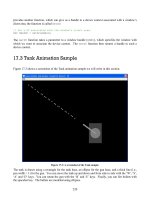
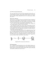
MMS architectural elements
T
he whole MMS environment (MMSE) encompasses all necessar
y
service
elements for delivery, storage, and notification. The elements can be located
w
ithin one network, or across several ne
t
works or network types. In the case of
t
t
roaming, the visited network is consider
e
d a
p
art of that user’s MMSE. However,
s
u
b
scr
ib
ers to anot
h
er serv
i
ce prov
id
er are cons
id
ere
d
to
b
e a part of a separate
M
M
S
E
.
Th
e MMS re
l
ay an
d
MMS server may
b
e a s
i
ng
l
e
l
og
i
ca
l
e
l
ement or may
b
e
s
eparate. T
h
ese can
b
e
di
str
ib
ute
d
across
di
fferent
d
oma
i
ns. T
h
e com
bi
nat
i
on
of t
h
e MMS re
l
a
y/
server
i
s t
h
e MMSC. It
i
s
i
n c
h
ar
g
e of stor
i
n
g
an
d
h
an
dli
n
g
later. If the message cannot be delivered within a certain time frame
,
it is eventu-
Y. Yang and R. Yan266
service, a set of network elements is organized as shown in Fig. 11.6 [[14]] .
26
7
among different messaging systems. It should be able to generate charging data
f
or MMS an
d
VAS prov
id
er-re
l
ate
d
operat
i
ons.
MM
S
user
d
ata
b
ase conta
i
ns
u
ser-re
l
ate
d
i
nformat
i
on suc
h
as su
b
scr
i
pt
i
on an
d
conf
i
gurat
i
on.
M
MS user a
g
ent is an application la
y
er function that provides the users with the
abilit
y
to view, compose, an
d
h
andle multimedia messa
g
es. It r
es
i
des
o
n th
e
user
e
q
ui
p
ment (UE) or on an external device connected to the UE or MS.
M
MS VAS a
pp
lications
p
rovide VAS to MMS users. They can be seen as fixed
M
MS user agents but with some addi
t
ional features like multimedia message
r
ecall between MMS VAS a
pp
lications a
n
d MMSC. MMS VAS a
pp
lications
sh
ou
ld
b
e a
bl
e to gen
e
rate t
h
e c
h
arg
i
ng
d
ata w
h
en rece
i
v
i
ng
/
su
b
m
i
tt
i
ng
mu
l
t
i
me
di
a messages from
/
to MMSC.
External servers ma
y
be included wit
h
i
n, or connected to, an MMSE, e.
g
.,
e-mail server, SMSC, and fax. MMSC would inte
g
rate different server t
y
pes
ac
r
oss
d
iff
e
r
e
nt n
e
t
wo
rk
s
an
d
provide conver
g
ence functionalit
y
between external
s
ervers and MMS user agents.
M
M1 is the reference point between the MMS user agent and the MMSC. It is
use
d
to su
b
m
i
t mu
l
t
i
me
di
a messages from MMS user agent to MMSC, to
l
et t
h
e
M
MS user agent pu
ll
mu
l
t
i
me
di
a messages from t
h
e
MMSC,
l
et t
h
e MMSC pus
h
i
nformat
i
on a
b
out mu
l
t
i
me
di
a messages to t
h
e MMS user Agent as a part of a
multimedia messa
g
e notification, and to
e
xchan
g
e deliver
y
reports between
M
MSC an
d
MMS user a
g
ent.
M
M2
i
s t
h
e reference
p
o
i
nt
b
etween t
h
e MMS re
l
a
y
an
d
t
h
e MMS server. Mos
t
M
MS solutions offer a combined MMS relay and MMS server as a whole MMSC.
This interface has not been s
p
ecified till now.
M
M3 is the reference
p
oint b
e
t
ween the MMSC and external messaging sys
-
MMSC. To prov
id
e f
l
ex
ibl
e
i
mp
l
ementat
i
on of
i
ntegrat
i
on of ex
i
st
i
ng an
d
new
f
ramework the MMSC communicates with both MMS user a
g
ent and external
s
ervers. It can
p
rovide con
v
er
g
ence functionalit
y
b
e
t
wee
n
e
xt
e
rnal
se
r
ve
r
s
an
d
MMS user a
g
ents, and thus ena
b
l
es the inte
g
ration of different server t
y
pes across
di
fferent networ
k
s.
M
M4
i
s t
h
e reference po
i
nt
b
etween t
h
e MMSC an
d
anot
h
er MMSC t
h
at
i
s
w
i
t
hi
n anot
h
er MMSE. It
i
s
i
n c
h
arge of transferr
i
ng messages
b
etween MMSCs
b
e
l
on
gi
n
g
to
di
fferent MMSEs. Interwor
ki
n
g
b
etween MMSCs w
ill
b
e
b
ase
d
on
11 Mo
bil
e
C
onten
t
De
li
ver
y
Tec
h
no
l
o
gi
es
MM5
i
s t
h
e reference po
i
nt
b
etween t
h
e MMSC an
d
t
h
e HLR. It may
b
e use
d
t
o provide information to the MMSC a
b
out the subscriber to the MMSC.
i
ncom
i
n
g/
out
g
o
i
n
g
messa
g
es an
d
i
s respons
ibl
e for t
h
e transfer of messa
g
es
tems. It
i
s use
d
by
t
h
e MMSC to sen
d
/
retr
i
eve mu
l
t
i
me
di
a messa
g
e
s
t
o/
fr
o
m
se
r
-
vers of externa
l
messa
gi
n
g
s
y
stems t
h
at are
co
nn
ec
t
ed
t
o
t
he
se
r
vice
prov
id
er’s
t
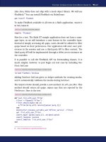
he MMS makes use of the
p
rotocol
f
ramework depicted in Fi
g
. 11.7. In this
In MMSE, elements communicate via a set of interfaces [14].
services together with interoperability across different networks and terminals [14],
SMTP according to IETF STD 10 (RFC2821) [15] shown in Fig. 11.8.
MMS Use
r
A
gent
M
M1 Trans
f
er
P
r
otocol
M
M1 Trans
f
er
P
r
otocol
M
M
3
Tr
a
n
s
f
e
r
P
rotoco
l
M
M
3
Tr
a
n
s
f
e
r
P
rotoco
l
Lower La
y
er A Lower La
y
er
A
L
ower La
y
er B
L
ower La
y
er B
e.g. TCP/UD
P
e.g. TCP/UDP
E
xterna
l
S
erver
MM
S
C
a
p
abl
e
UE/M
S
M
M
SE
M
M1 MM
3
MS
C
MM
M
P
rotocol tlements necessar
y
in the terminal
P
rotocol tlements necessar
y
in the MM
S
E
Additional protocol elements necessary to include external servers
Fig. 11.
7
. Protocol framework to
p
rovide MMS
M
M
S
Use
r
Ag
ent
A
MM
S
User
Ag
ent
B
M
M
SC
A
MM
SC
B
S
MTP
MM
1
MM
1
MM4
M
M
SE
S
ervice Provider A
M
M
SE
S
ervice Provider
B
F
i
g
. 11
.
8
.
Interworkin
g
of different MMSEs
M
M6 is the reference
p
oint between the MMSC and the MMS user database.
M
M7 is the reference
p
oint between the MMSC and the MMS VAS a
pp
lica-
tions. It allows multimedia messages transferring from/to MMSC to/from MMS
M
M8
i
s t
h
e reference
p
o
in
t
b
etween MMSC an
d
t
h
e postprocess
i
ng system. I
t
is needed when transfering MMS-specific CDRs from MMSC to the operators in
th
e postprocess
i
ng system.
MM9
i
s t
h
e reference po
i
nt
b
etween MMSC
a
n
d
on
li
ne c
h
arg
i
ng system. It
i
s
u
se
d
to transfer c
h
ar
gi
n
g
messa
g
es from MMSC to t
h
e on
li
ne c
h
ar
gi
n
g
s
y
stem.
Y. Yang and R. Yan268
VAS applications. This interface will be based on SOAP 1.1 [16] and SOAP mes-
sages with attachments [17] using an HTTP transport layer.
269
1
1.
3
.
5
Transact
i
ons
T
here are four typical MMS transactions:
•
M
obile-originate
d
(MO) transactio
n
i
s originated by an MS. The multi-
m
e
di
a messages are sent
di
rect
l
y to an MS or poss
ibl
y to an e-ma
il
a
dd
ress. If some sort of process
i
ng
/
convers
i
on
i
s nee
d
e
d
, t
h
e mu
l
t
i
me
di
a
•
M
obile-terminate
d
(
MT
)
transaction sends the messa
g
es to an MS. The
originator of such messages can be a
nother MS or an application.
a
a
•
A
pplication originate
d
(AO) transactio
n
is originated by an application
and terminated directly an MS or a
n
other a
pp
lication. Before the multi-
m
e
di
a messa
g
es are sent to t
h
e
d
est
i
nat
i
on, t
h
e
y
can
b
e processe
d
i
n one
or more app
li
cat
i
ons.
•
A
pplication-terminated (AT) transaction
i
s term
i
nate
d
at an app
li
cat
i
on
and ori
g
inated b
y
an MS or anothe
r
a
pp
lication. As noted in MO transac-
t
ion, the multimedia messa
g
es can be sen
t
to an a
pp
lication that does the
processin
g
/conversion, so it is actuall
y
an AT transaction.
Based on these four types of transactions, transactions for each interface are re
-
a
lized that can be described in terms of abstract messages. The abstract messages
c
an be categorized into transactions
c
onsisting of “re
q
uests” and “res
p
onses.” To
l
a
b
e
l
t
h
e a
b
stract messa
g
e, t
h
e tra
n
sact
i
ons for a certa
i
n
i
nterface are pref
i
xe
d
by
i
ts name, e.
g
., t
h
e tra
n
s
a
c
t
io
n
s
f
o
r MM1 ar
e
p
ref
i
xe
d
w
i
t
h
“MM1.” Bes
id
es,
“requests” are
id
ent
i
f
i
e
d
w
i
t
h
“.REQ” as a suff
i
x an
d
“responses” are
id
ent
i
f
i
e
d
with the “.RES” suffix.
E
ach abstract messa
g
e carries certain IEs, which ma
y
var
y
accordin
g
to the spe
-
c
ific message. All messages carry a protocol version and message type, so that the
MMSE components are able to properly identify and manage the message contents.
T
he mapping of abstract messages to specific protocols is not necessarily a one-to-
o
ne re
l
at
i
ons
hi
p. Depen
di
ng on t
h
e MMS WAP
i
mp
l
ementat
i
on, one or more
ab
stract messages may
b
e mappe
d
to a s
i
ng
l
e
l
ower
l
ayer PDU an
d
v
i
ce versa. T
h
e
following clause uses MM1 WAP im
plementation for further discussion.
m
m
11.3.6 WAP Im
p
lementation of MM1
As noted earlier, WAP addresses the
p
rotocol im
p
lementation of the
p
articular
i
nterface. Now, MMS activities of the WAP Forum have been inte
g
rated to OMA.
T
here are two different confi
g
urations of the WAP architecture and protocol
1
1 Mo
bil
e
C
onten
t
D
e
li
very Tec
h
no
l
og
i
es
m
essages are f
i
rst are sent to an app
li
cat
i
on t
h
at
d
oes t
h
e process
i
ng
/
convers
i
on, an
d
t
h
en to t
h
e
d
est
i
nat
i
on.
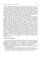
stacks for im
p
lementation of MMS as
s
hown in Fig. 11.9 and Fig. 11.10.
F
i
g
. 11
.
9
.
Im
p
lementation of MM1 inte
r
f
ace usin
g
WAP 1.x
g
atewa
y
normally transferred using a wireless trans
p
ort such as WSP.
T
he second lin
k
connects the WAP gateway and the MMSC. In the WAP architecture the MMSC
i
s cons
id
ere
d
as or
i
g
i
n server. Messages trans
i
t over HTTP from t
h
e WAP gate-
way to t
h
e MMSC. T
h
e WAP gateway
p
rov
id
es a common set of serv
i
ces over a
var
i
ety of w
i
re
l
ess
b
earers
b
y us
i
ng “WAP stac
k
,” w
hi
c
h
i
nc
l
u
d
es WSP
i
nvocat
i
on
of HTTP methods; WAP PUSH services; OTA securit
y
; and capabilit
y
ne
g
otia-
tions (UAProf). The “Pa
y
load” represents the MMS application la
y
er protocol
data units (PDUs), which is carried b
y
WAP and HTTP. The structure of PDUs
i
s described later.
F
ig. 11.
10
. Implementation of MM1 interface using HTTP-based protocol stack
An examp
l
e of en
d
-to-en
d
transact
i
ons t
h
at occur
b
etween t
h
e MMS user agent
carr
y
MMS PDUs
di
rect
ly
b
etween t
h
e MMS user a
g
ent an
d
t
h
e MMSC, an
d
a
g
atewa
y
i
s on
ly
nee
d
e
d
f
or pus
h
funct
i
ona
li
t
y
. A
g
atewa
y
i
s om
i
tte
d
i
n
Fi
g
. 11.9 shows the WAP 1.x arch
i
t
ec
t
u
r
e
w
ith t
wo
link
s.
Th
e
fir
s
t i
s
be
t-
ween the wireless MMS user agent and the WAP gateway, and the messages are
Fig. 11.10 shows a different arc
h
i
tectural configuration. HTTP is used to
F
i
g. 11.10.
an
d
t
h
e MMSC
i
s
d
ep
i
cte
d
i
n F
i
g. 11.11.
Y. Yang and R. Yan270
271
T
he transactions on MM1 interface utilize a variet
y
of transport schemes, e.
g
.,
abstract messages. The MMS user agent issues a multimedia message by sending
an M-Send.req to the MMSC using a WSP/HTTP POST method. This operation
t
ransmits the re
q
uired data from the
M
MS user agent to the MMSC as well as
p
rov
id
es a transact
i
ona
l
context for t
h
e resu
l
t
i
ng M-Sen
d
.conf response. T
h
e
MMSC uses WAP PUSH tec
h
no
l
ogy to sen
d
th
e M-Not
i
f
i
cat
i
on.
i
n
d
to t
h
e MM
S
u
ser agent to
i
nfor
m
t
h
e ava
il
a
bili
ty of mu
l
t
i
me
di
a message for retr
i
eva
l
. T
h
e URI
o
f the multimedia messa
g
e is also includ
e
d in the data. In the URI, the MMS user
ag
ent uses the WSP/HTTP GET method to retrieve the messa
g
e. The fetchin
g
of
t
he URI returns the M-retrieve.conf, which contains the actual multimedia mes
-
sage to be presented to the user. The M-Acknowledge.ind passed from the MMS
u
ser agent to MMSC is to indicate that the message is actually received by the
MMS user agent. An
d
t
h
e MMSC
i
s respons
ibl
e for prov
idi
ng a
d
e
li
very repor
t
b
ac
k
to t
h
e or
i
g
i
nator MMS user agent aga
i
n ut
ili
z
i
ng t
h
e WAP PUSH tec
h
no
l
ogy
w
i
t
h
t
h
e M-De
li
very.
i
n
d
message.
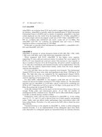
E
ach abstract messa
g
e ma
y
be mapped to one or more lower la
y
er PDUs,
w
hi
c
h i
s
d
i
scussed
in the followin
g
.
M
M
SC
Ori
g
inator MMS
U
ser
Ag
en
t
Reci
p
ient MMS
U
ser
Ag
en
t
M
-Send.re
q
M
-
S
end.con
f
M
-N
o
tifi
ca
ti
o
n.in
d
M-Noti
fy
Resp.in
d
WSP GET.req
M-r
e
tri
e
v
e
.
co
nf
M
-
A
c
k
now
l
e
dg
e.
i
n
d
M
-
D
e
li
very.
i
n
d
F
i
g
. 11
.
11
.
Exam
p
le of MMS transactional flow in WAP
1
1.3.7 Structure
In the earlier transaction, most messa
g
es are sent as MMS PDUs. An MMS PDU
may consist of MMS headers and MMS body; also it can include only headers.
T
he MMS PDUs are, in turn,
p
assed in the content section of WAP or HTTP mes
-
s
ages, an
d
t
h
e content type of t
h
ese messages
i
s set as app
li
cat
i
on
/
vn
d
.wap.mms
-
message.
11 Mo
bil
e
C
onten
t
D
e
li
ver
y
Tec
h
no
l
o
gi
es
The MMS headers contain MMS-specific information of the PDU, mainly
about how to transfer the multimedia message from the originating terminal to the
recipient terminal. The MMS body includes multimedia objects, each in separate
part, as well as optional presentation part. The order of the parts has no signifi-
cance. The presentation part contains instructions on how the multimedia content
should be rendered on the terminal. There may be multiple presentation part, but
one of them must be the root part; in the case of multipart/related, the root part is
pointed from the Start parameter. Examples of the presentation techniques are
WSP Header
Content-type:
application/vnd.wap.mms-message
WSP Content
MMS Header
MMS Body
Presentation
image/jpeg
text/plain
audio/wav
Start
Fig. 11.12. Model of MMS data encapsulation and WSP message
The MMS headers consist of header fields that in general consist of a field
name and a field value. Some of the header fields are common header fields and
others are specific to MMS. There are different types of MMS PDUs used for dif-
ferent roles, and they are distinguished by the parameter “X-Mms-Message-Type”
in MMS headers. Each type of message is with a kind of MMS headers with par-
ticular fields.In the earlier example, the M-Send.conf message contains an MMS
11.3.8 Supported Media and File Formats
Multiple media elements can be combined into a composite single multimedia
support media types should comply with the following selection of media formats:
header only and it includes several fields listed in Table 11.3.
Fig. 11.12 is an example of how multimedia content and presentation information
Y. Yang and R. Yan272
can be encapsulated to a single message and be contained by a WSP message [18].
synchronized multimedia integration language (SMIL) [19], wireless markup lan-
guage (WML) [20], and XHTML.
message using MIME multipart format as defined in RFC 2046 [21]. The minimum
2
7
3
T
able 11.
3
.
M
-Sen
d
.conf messa
g
e
fi
e
ld
name f
i
e
ld
content
d
escr
i
pt
i
o
n
X-Mms-Message-Typ
e
M
essage-type-va
l
ue =
m-not
i
f
y
resp-
i
n
d
man
d
atory
s
pec
i
f
i
es t
h
e PDU typ
e
X-Mms-Transact
i
on-I
D
Transact
i
on-
id
-va
l
u
e
man
d
atory
id
ent
i
f
i
es t
h
e transact
i
on
s
tarte
d
b
y M
-
N
ot
i
f
i
cat
i
on.
i
n
d
PD
U
X-Mms-MM
S
-
V
ers
i
o
n
M
M
S
-vers
i
on-va
l
u
e
man
d
atory
t
h
e MM
S
vers
i
on num
b
er.
X-Mms-
S
tatus
S
tatus-va
l
u
e
man
d
atory
message status. T
h
e status
r
etr
i
eve
d
w
ill
b
e use
d
on
l
y
aft
e
r
success
f
ul
r
e
tr
iev
a
l
of
t
he
MM
X-Mms-Report
-
A
llowed
Report-a
ll
owe
d
-va
l
u
e
opt
i
ona
l
. Defau
l
t: Yes.
i
n
di
cat
i
on of w
h
et
h
er or no
t
•
T
ext.
p
lain text must be supported. Any
c
haracter encoding that contains
a subset of the logical characters in unicode can be used.
•
Speec
h
.
the
A
RM
c
o
d
ec supports narrow
b
an
d
speec
h
. T
h
e ARM w
id
e
-
b
an
d
(
ARM-WB
)
speec
h
co
d
ec of 16-
k
Hz samp
li
n
g
frequenc
y
i
s sup
-
p
orte
d
. T
h
e ARM an
d
ARM-WB
i
s use
d
for speec
h
me
di
a-t
y
pe a
l
one.
•
Audio
. MPEG-4 AAC low complexit
y
ob
j
ec
t
t
y
pe with a samplin
g
rate
u
p
to 48 kHz is su
pp
orted. The chan
n
el confi
g
urations to be supported
are mono
(
1
/
0
)
an
d
stereo
(
2
/
0
)
. In a
ddi
t
i
on, t
h
e MPEG-4 AAC
l
ong-term
p
re
di
ct
i
on o
bj
ect type m
a
y
b
e supporte
d
.
•
Synthetic audio.
Th
e sca
l
a
bl
e po
l
yp
h
ony MIDI
(
SP-MIDI
)
content format
requ
i
rements
d
ef
i
ne
d
i
n sca
l
a
bl
e p
o
ly
p
h
on
y
MIDI
d
ev
i
ce
5-t
o
-24 n
o
t
e
11 Mobile Conten
t
Deliver
y
Technolo
g
ies
A
ccor
di
n
g
to t
hi
s
spec
i
f
i
cat
i
on, t
h
e vers
i
on
i
s
1
.
2
r
eport
i
s a
ll
owe
d
by
t
h
e
t
h
e sen
di
n
g
of
d
e
li
ver
y
r
eci
p
ient MMS clien
t
defined in scalable polyphony MIDI specification [22] and the device
profile for 3GPP [23] are supported. SP-MIDI content is delivered in the
•
Still image. ISO/IEC JPEG together with JFIF is supported. When sup
-
p
orting JPEG, baseline DCT is mandatory while progressive DCT is
opt
i
ona
l
.
•
B
itmap
g
rap
h
ics. GIF87a, GIF89a, an
d
PNG
bi
tmap
g
rap
hi
cs formats are
s
u
pp
orted.
•
Vi
d
e
o
.
The mandator
y
video codec for the MMS is ITU-T recommenda
-
tion H.263
p
rofile 0, level 10. In ad
d
ition, H.263 Profile 3
,
Level 10, and
M
PEG-4 Visual Sim
p
le Profile Level 0 are o
p
tional to im
p
lement.
•
Vector grap
h
ics. For term
i
na
l
s support
i
ng me
d
i
a type “2D vector grap
h-
i
cs” t
h
e “T
i
ny” prof
il
e of t
h
e sca
l
a
bl
e vector grap
hi
cs
(
SVG-T
i
ny
)
format
i
s supporte
d
, an
d
t
h
e “Bas
i
c” prof
il
e of t
h
e sca
l
a
bl
e vector
g
rap
hi
cs
(
SVG-Bas
i
c
)
format ma
y
b
e supporte
d
.
•
File
f
ormat
f
or d
y
namic media
.
To ensure
i
ntero
p
era
bili
t
y
for t
h
e trans
-
p
ort of video and associated s
p
eech/audio and timed text in a multimedia
messa
g
e, the 3GPP file format is supported.
•
Media synchronization and
presentation
f
ormat.
d
T
he mandator
y
format
f
or me
di
a sync
h
ron
i
zat
i
on an
d
sce
n
e
d
escr
i
pt
i
on of mu
l
t
i
me
di
a messag-
i
ng
i
s SMIL. T
h
e 3GPP MMS uses a su
b
set of SMIL 2.0 as t
h
e format o
f
t
h
e scene
d
escr
i
pt
i
on. A
ddi
t
i
ona
lly
,
3
GPP MMS s
h
ou
ld
prov
id
e t
h
e for
-
mat of XHTML mo
bil
e prof
il
e.
•
D
RM
f
orma
t
. T
h
e support of DRM
i
n MMS conforms to t
h
e OMA DRM
f
ormat of OMA DRM content format
(
DCF
)
for
di
screte me
di
a an
d
1
1.3.9 Client-Side Structure
T
he
g
eneral model of how the MMS user a
g
ent fits within the
g
eneral WAP Clien
t
T
h
e MMS user agent
i
s respons
ibl
e for t
h
e compos
i
t
i
on an
d
ren
d
er
i
ng of mu
l
-
t
i
me
di
a messa
g
es as we
ll
as sen
di
n
g
an
d
rece
i
v
i
n
g
mu
l
t
i
me
di
a
m
essa
g
es
by
ut
ili
z
-
ing the message transfer services of the a
ppropriate network protocols. The MMS
a
a
user agent is not dependent on, but may use, the services of the other components
s
hown in Fig. 11.13, i.e., the common functions, WAP identity module (WIM)
OMA
p
acketized DRM content format (PDCF) for
p
acketized (continuou
s
or format 1.
precedence over message distribution indication and over MM7 content
adaptation registration from REL-6 onward. The protected files are in the
Y. Yang and R. Yan274
structure specified in standard MIDI files 1.0 [24], either in format 0
specifications [25]. DRM protection of a multimedia message takes
media [26].
architecture is depicted in Fig. 11.13 [18].
[27] and external functionality interface (EFI) [28].
27
5
Application Framework
(WAE User Agent, Push Dispatcher, MMS Uer Agent)
Network
Protocols
Content Renderers
(Images, Multimedia, ect.)
Common Functions
(Persistence, Sync, etc.)
WIM
EFI
Fig
. 11.
13
.
G
enera
l
W
AP c
li
ent arc
hi
tecture
11.4 Transcoding Techniques
In this section
,
we focus on progresses in conten
t
t
ranscoding techniques. We
i
ntroduce the prevailing status and give details of some transcoding techniques
wi
t
h
di
fferent me
di
a types. As an
a
pp
li
cat
i
on an
d
en
h
ancement of content
transco
di
n
g
, we a
l
so
i
ntro
d
uce some p
r
o
g
resses
i
n a
d
apt
i
ve content
d
e
li
ver
y
an
d
s
calable content codin
g
.
1
1.4.1 Transcod
i
ng – The Br
i
dge
f
or
C
ontent Del
i
very
Because of the various mobile computing technologies involved, multimedia con-
tent access on mo
bil
e
d
ev
i
ces
i
s poss
ibl
e. W
hil
e stat
i
onar
y
comput
i
n
g
d
ev
i
ces
s
uc
h
as PCs an
d
STBs
h
a
d
mu
l
t
i
me
di
a support
l
on
g
b
efore, mo
bil
e
d
ev
i
ces
h
ave
sp
ecial features that make them differen
t
f
rom stationar
y
computin
g
devices. Due
to limitations of design and usability,
m
obile devices normally have lower com
-
p
ut
i
ng power, sma
ll
er an
d
l
ower reso
l
ut
i
on
di
sp
l
ay,
li
m
i
te
d
storage, s
l
ower an
d
l
ess re
li
a
bl
e networ
k
connect
i
ons
,
an
d
l
ast
b
ut
i
mportant
l
y,
li
m
i
te
d
user
i
nteract
i
on
i
nterfaces. As a result, onl
y
speciall
y
tailored
c
o
nt
e
nt
s
c
an ha
ve
th
e
bes
t
use
r
experiences on these devices. In this case, content creators ma
y
choose to produce
contents specifically for mobile devices. However, large quan
t
iti
es
o
f m
u
ltim
ed
ia
contents an
d
d
ocuments
h
ave a
l
rea
d
y
b
een create
d
for stat
i
onary comput
i
ng
d
ev
i
ces w
i
t
h
high
b
an
d
w
id
t
h
an
d
p
rocess
i
n
g
capa
bili
t
i
es. Convert
i
n
g
t
h
ese ex
i
st
-
i
n
g
contents to fit the special re
q
uirements of the mobile devices is another more
cost-effective and reasonable a
pp
roach. The
p
rocess that does this conversion is
called transcoding.
G
enera
lly
spea
ki
n
g
, we can
d
ef
i
ne tr
a
nsco
di
n
g
as t
h
e process of transform
i
n
g
contents from one re
p
resentation format or leve
l
o
f
de
tail
s
t
o
an
o
th
e
r
o
n
e.
In
so
m
e
11 Mo
bil
e
C
onten
t
D
e
li
very Tec
h
no
l
og
i
e
s
c
ases, transco
di
ng can
b
e tr
i
v
i
a
l
an
d
can ta
k
e p
l
ace w
h
en t
h
e contents are
b
e
i
ng
s
erved, while in man
y
cases, for example video transcodin
g
, the process requires
heavy computing power and offline process. For multimedia stream contents, fo
r
exam
p
le, audio and video, a s
p
ecific transcoding scenario exists, which is to
reduce the bit rate to meet some specific channel capacity. This specific process is
common
ly
referre
d
to as transrat
i
n
g
.
T
o e
li
m
i
nate t
h
e comp
l
ex
i
t
y
of transco
di
n
g
, sca
l
a
bl
e co
di
n
g
tec
h
no
l
o
gi
es
h
ave
b
een a
d
opte
d
. In common
,
di
fferent
l
a
y
ers of
d
eta
il
an
d
qua
li
t
y
of t
h
e same con
-
t
e
nt
s
ar
e
in
c
l
uded
in th
e
codin
g
schemes. These la
y
ers ma
y
represent differen
t
sp
atial/tem
p
oral resolutions and/or di
f
ferent bit rates/qualities. Hi
g
her qualit
y
or
resolution layers may depend on lower quality or resolution layers. Typical exam
-
Wi
t
h
t
h
e
i
ncreas
i
ng
di
vers
i
ty an
d
h
eterogene
i
ty of conten
t
s
,
c
li
ent
d
ev
i
ces an
d
n
etwor
k
con
di
t
i
ons com
bi
ne
d
w
i
t
h
i
n
di
v
id
ua
l
preferences of en
d
users, mere
transcodin
g
s cannot handle the com
p
lexities. A
d
a
p
tive content deliver
y
is the s
y
s
-
tem solution that meets the re
q
uirement
s
. Contents are
g
enerated, selected, o
r
transcoded d
y
namicall
y
accordin
g
to factors, includin
g
the user’s preferences,
d
evice capabilities, and network conditions. In this way, it allows better use
r
experience under the changing circumstances.
In the following sections, we first give
a
n overview of existing transcoding
tec
h
no
l
og
i
es for
di
fferent me
di
a types. T
h
en
d
eta
il
s of some transco
di
ng a
l
go
-
r
i
t
h
ms regar
di
ng
di
fferen
t
me
di
a types are
di
scusse
d
. Later, we
i
ntro
d
uce t
h
e pro
-
g
resses of a
d
apt
i
ve content
d
e
li
very an
d
sca
l
a
bl
e content co
di
ng tec
h
no
l
og
i
es.
1
1.4.2 Overview
T
ranscodin
g
can be applied to different content such t
y
pes and formats. In this
s
ect
i
on, we focus on common
ly
use
d
content t
y
pes as v
id
eo, au
di
o,
i
ma
g
e, an
d
f
ormatte
d
d
ocument, an
d
our
di
scuss
i
ons are
li
m
i
te
d
to some s
p
ec
i
f
i
c content
f
ormats.
11.4.3 Image Transcoding
B
efore video was incorporated into the di
g
ital media era, ima
g
es were the mos
t
important 2D visual media types for com
puter users. From the exchange of GIF
m
m
pi
ctures on UseNet, to t
h
e
b
oom
i
n
g
of Wor
ld
W
id
e We
b
,
i
ma
g
es occup
y
a
l
ar
g
e
T
a
bl
e 11.4
gi
ves a summar
y
of t
y
p
i
ca
l
transco
di
n
g
met
h
o
d
s t
h
at are fre-
q
uentl
y
used in producin
g
con
t
e
nts for mobile devices. Some
p
eo
p
le consider th
e
techni
q
ues to add more redundan
t
information for error resilience and recovery with
t
error-prone wireless network channels as transcodin
g
. In our opinion, we would
rather
p
refer to treat them as robust content coding and channel coding techniques
.
Transcoding requirements such as transrating and spatial resolution change thus
become simple selections among different layers.
Y. Yang and R. Yan276
ples are the scalable coding schemes in MPEG-2 and MPEG-4 video [29].
277
p
ort
i
on of Internet contents. W
i
t
h
t
h
e
i
ncrease
d
digi
ta
l
i
ma
gi
n
g
capa
bili
t
i
es of
d
ev
i
ces
lik
e mo
bil
e p
h
ones an
d
i
nfrastructure supports suc
h
as MMS,
i
ma
g
es are
also becomin
g
an important content t
y
pe on mobile devices.
Basicall
y
, there are two classes of ima
g
es. One is bitmap, the other is vector
g
raph-
i
cs. The contents created with 2D di
g
ital
i
ma
g
in
g
devices and pa
i
ntin
g
applications
are normally bitmap images. The basic unit of the bitmap images is pixel. A pixel is
a s
i
ng
l
e po
i
nt or
d
ot on t
h
e
bi
tmap
i
mage. A
bi
tmap
i
mage
i
s compose
d
of a 2D
matr
i
x of p
i
xe
l
s. Eac
h
p
i
xe
l
h
as a va
l
ue t
h
at e
i
t
h
er represents a co
l
or or an
i
n
d
ex to
some co
l
or pa
l
ette. T
hi
s va
l
ue can
b
e from 1
bi
t to 64
bi
ts or more
d
epen
di
n
g
on t
h
e
bi
tmap t
y
pes an
d
co
l
or reso
l
ut
i
ons. B
i
tmap
i
ma
g
es are
also
c
a
lled
r
a
ster
i
ma
g
es
because the
y
can be directl
y
mapped to rast
er graphics displays t
hat we commonly
t
t
u
se. Vector
g
raphics take a different road. The basic units of vector
g
raphics are
g
eometrical elements such as lines, curves, shapes, fills, etc. Some vector
g
raphic
f
ormats also allow embedding of bitmap images. Both bitmap and vector images
have their
p
ros and cons. For exam
p
le, bitmap images are superior in representing
nature scenes and can be rendered to the raster graphics displays we commonly use.
In case of
g
eometr
i
ca
l
transformat
i
ons suc
h
a
s sca
li
n
g
, rotat
i
n
g
, an
d
d
eform
i
n
g
,
bi
t
-
map
i
ma
g
es norma
lly
suffer from qua
li
t
y
l
osses
b
ecause of t
h
e
i
nterpo
l
at
i
ons use
d
to
map t
h
e p
i
xe
l
s to
di
fferent
l
ocat
i
ons. On t
h
e contrar
y
, vector
g
rap
hi
cs can represent
hi
g
h resolution artificial drawin
g
s and can be t
r
a
nsformed without losin
g
informa
-
t
ion. But the
y
are weak in representin
g
nature scenes, and displa
y
in
g
vector ima
g
es
on the raster displa
y
de
v
ices requires rasterizin
g
processes.
T
here are many image file formats in use. Some commonly used formats are
PNG, and SVG. Since su
pp
ort of vecto
r
graphics such as SVG in browsers and
r
d
raw
i
ng app
li
cat
i
ons
i
s yet to come, we
li
m
i
t our fo
ll
ow
i
ng
d
i
scuss
i
on to
bi
tmap
i
mages.
I
ma
g
e Format
C
onvers
i
on
Ima
g
e format conversion with bitmap files ma
y
simpl
y
be done b
y
some applica
-
t
ions that could su
pp
ort loading and saving of image files in different formats. One
,
which claims to su
pp
ort over 89 file formats. There are, however, some s
p
ecial
p
rove t
h
e performance of GIF to JPEG-LS
c
onvers
i
on
i
s
di
scusse
d
.
G
IF uses t
h
e
f
rom t
h
e cont
i
nuous tones
i
n a
dj
acent areas of p
h
otos. T
h
e approac
h
attac
k
s t
h
e
optimization b
y
reorderin
g
the palette index of
G
IF to emulate a continuous tone
nei
g
hborhood for pixels. Thus it can be handled better b
y
JPEG-LS. With the spe
-
cial reorderin
g
, JPEG-LS outperforms GIF in
g
eneral.
C
olor
S
pace
C
onvers
i
on
W
e live in a colorful world. Naturall
y
so are the ima
g
es. L
i
mited b
y
the device
capabilities, file formats, and stora
g
e requirements, ima
g
es ma
y
need to be con
-
verted to different color re
p
resentations. Fo
r
example, true color images convert to
11 Mo
bil
e
C
onten
t
De
li
very Tec
h
no
l
og
i
es
example of such applications is Ima
g
e
Ma
g
ick (
g
ema
g
ick.or
g)
cases where more thorough studies show improvements. In [31], a method to im-
LZW [32] compression for generic string compression, while JPEG-LS benefits
listed in [30]. In Web contents, the recommended image file formats are GIF, JPEG,
p
alette ima
g
es or
g
ra
y
scale ones. There are d
i
f
f
e
r
e
nt m
e
th
ods
t
o
co
n
ve
rt tr
ue
color images to gray scale ones and each met
hod results in different visual styles.
t
T
he most commonly used approach with RGB colors is the color space conversio
n
matrix borrowed from N
T
S
C TV standards as shown by the following equation.
source t
y
pe
T
ranscodin
g
metho
d
r
esult t
y
pe Exam
p
les
encoding format conversion
v
ide
o
M
PEG-1 to MPEG-
4
T
ransrat
i
n
g
video
5
Mb
p
s DVD to 1
Mb
p
s MPEG-
4
spat
i
a
l
reso
l
ut
i
o
n
re
d
uct
i
on v
id
eo
C
IF to
QC
I
F
v
i
deo
30 f
p
s to 10 f
ps
k
ey frame extractio
n
i
mag
e
summar
y
of t
y
pical
scenes
video
sou
n
d
tra
c
k
e
xtra
c
ti
o
na
ud
i
o
film
sou
n
d
tra
ck
encoding format conversio
n
audio CD audio to MP
3
transrat
i
n
g
a
u
di
o
3
20 kb
p
s MP3 to 128
kb
ps
c
hann
e
l
dow
n mi
x
aud
i
o
5
.1 c
h
anne
l
s surroun
d
to 2 c
h
anne
l
s stere
o
s
amplin
g
rate chan
g
e
aud
i
o
4
4
.
1 kHz t
o
8 kH
z
s
amplin
g
resolution chan
ge
aud
i
o
16
b
it
s
t
o
8
b
it
s
audio summar
y
aud
i
o
s
am
p
le cli
ps
a
ud
i
o
sp
eech detection
t
ex
t
s
peech recognitio
n
encoding format conversio
n
image
P
NG to JPE
G
transrating image
J
PEG re
q
uantizatio
n
s
pat
i
a
l
reso
l
ut
i
on re
d
ut
i
on
i
mage
XGA 1024
×
7
68 to
VGA
640
×
480
color s
p
ace conversio
n
image color to gray scale
s
amplin
g
resolution chan
ge
ima
g
e
2
4-
bi
t R
G
B to 16-
bit
5
65R
G
B
ROI detectio
n
ima
g
e
p
art of or
i
g
i
na
l
i
mage
as re
g
ion of interests
i
ma
ge
image
b
itma
p
to vector o
r
v
i
ce
ve
r
s
a
f
ormat conversion
d
ocumen
t
HTML to WMLdocument
text to speec
h
a
u
dio
s
creen rea
d
er
screen ren
d
er
i
ng
p
resentation slides to
PN
G
s on
W
e
b
i
ma
g
e
Y
=
0
.299 * R
+
0
.587 *
G
+
0
.114 * B (11.1)
r
educ
t
ion
tempora
l
reso
l
ut
i
on
co
n
ve
r
s
i
o
n
r
e
p
resentation format
Ta
b
l
e
11
.
4.
Content t
y
pes and transcodin
g
methods
Y. Yang and R. Yan278
2
79
T
o convert a true co
l
or
i
mage to t
h
e
li
m
i
te
d
co
l
ors of a pa
l
ette
i
mage, t
h
ere w
ill
certainly be loss of visual quality. For exam
ple, a 24-bit RGB image can represent
m
m
2
24
an
d
di
t
h
er
i
n
g
are use
d
. Co
l
or qua
n
t
i
zat
i
on
i
s t
h
e process to se
l
ect a su
i
ta
bl
e co
l
o
r
p
a
l
ette an
d
map eac
h
p
i
xe
l
of t
h
e or
igi
na
l
i
ma
g
e to an
i
n
d
ex of t
h
e pa
l
ette. W
i
t
h
the limited number of colors a
pa
l
ette represents, the mismatchin
g
pixels ma
y
cause si
g
nificant visual artifacts especiall
y
in the area
o
f continuous tone chan
g
es.
si
mu
l
ate
d
cont
i
nuous tones. At some
di
stances,
h
uman v
i
s
i
on systems w
ill
ten
d
to
examp
l
e of
i
ma
g
e quant
i
zat
i
on an
d
di
t
h
er
i
n
g
.
Fi
g
. 11.
14
.
Example of ima
g
e quantization and ditherin
g
.
(
a
)
Ori
g
inal,
(
b
)
q
uan-
t
ization to four levels, and
(
c
)
dithered resul
t
Regarding color quantization, there are many methods. The Color Maker of
T
om Boyle and Andy Lippman in late 197
0
’s uses a
p
o
p
ula
r
ity algorithm. The
y
quantize the 24-bit RGB image first to 15-bit RGB with each color component in
5
bi
ts. T
hi
s w
ill
a
ll
ow t
h
e comput
i
ng to
b
e reasona
bl
e for
h
ar
d
ware at t
h
at t
i
me
w
hil
e st
ill
preserv
i
ng
b
eara
bl
e qua
li
ty
l
osses. T
h
en t
h
e
d
ensest c
l
usters of p
i
xe
l
di
str
ib
ut
i
on
i
n t
h
e 2
5
*
2
5
*2
5
co
l
or space cu
b
e w
ill
b
e c
h
osen as t
h
e pa
l
ette an
d
a
ll
p
roposed. The palette is chosen under constraints of makin
g
each entr
y
cover an
approximatel
y
equal number of pixels in
t
he ima
g
e. The al
g
orithm does this b
y
di-
viding the color cube into smaller rectangular boxes until the number of boxes
e
q
uals that of
p
alettes. Each division m
a
kes sure that the number of
p
ixels in the
two parts is equal. Thus each box will finally contain similar number of pixels.
i
n t
h
e co
l
or va
l
ue
hi
sto
g
r
am an
d
t
h
en opt
i
m
i
ze
i
t
i
terat
i
ve
l
y
b
y app
l
y
i
ng t
h
e
11 Mobile Conten
t
D
eliver
y
Technolo
g
ies
= 16
,
777
,
216 co
l
ors
,
w
h
il
e an 8-
bi
t pa
l
ette
i
mage
c
an on
l
y represent 256
co
l
ors. In or
d
er to
k
eep m
i
m
i
c v
i
sua
l
qua
li
t
y
, tec
h
n
i
ques suc
h
as co
l
or quant
i
zat
i
on
cess of transform
i
ng
i
mages of cont
i
nuous tones to
i
mages of
li
m
i
te
d
tones w
i
t
h
perceive the halftone images as images of
continuous tones. Fig. 11.14 gives an
f
Halftone technique [33] is then used as a remedy. Generally speaking, it is the pro-
other unmatched colors are remapped to these. In [34], the media cut algorithm is
The author of [35] proposes to start the initial palette from the most popular entries
Linde–Buzo–Gray algorithm [36]. A hierarchical binary tree splitting based method
e
n
t
ry.
Ha
l
ftone
h
as
b
een
i
n pract
i
ce
f
or over a
h
un
d
re
d
years
in
t
h
e pr
i
nt
i
ng
i
n
d
ustry.
a
d
vances
i
n
digi
ta
l
i
ma
gi
n
g
tec
h
no
l
o
gi
es
,
man
y
new
h
a
l
ftone met
h
o
d
s
h
ave
b
een
na
l
tec
h
n
i
que
i
s st
ill
l
ar
g
e
ly
i
n use even to
d
a
y
. T
h
e
b
as
i
c
id
ea
i
s to
di
ffuse t
h
e
e
rrors between ori
g
inal pixels and resultin
g
pixels to nei
g
hborin
g
pixels in the
resultin
g
ima
g
es. The diffusin
g
is done in
a
w
ei
g
hted wa
y
as shown in Fi
g
. 11.15.
T
he calculations are carried out in scan lines. Each
p
ixel will diffuse its errors to
f
our ne
i
g
hb
or
i
ng p
i
xe
l
s. Later on, ma
n
y researc
h
ers
h
ave ma
d
e more
d
eta
il
e
d
stu
d
y of t
h
e
di
t
h
er
i
ng a
l
gor
i
t
h
ms,
i
nc
l
u
di
ng those proposed by
Jarvis, Judice and
y
F
ig. 11.15
.
F
l
oy
d
–Ste
i
n
b
erg
di
t
h
er
i
ng
T
raditionally, color quantization and dithering h
a
s
been done sequentially.
W
hil
e
i
n t
hi
s way, t
h
e
di
t
h
er
i
ng step may c
h
ange t
h
e opt
i
ma
l
di
str
ib
ut
i
ons t
h
e
quant
i
zer tr
i
es to atta
i
n, t
h
e resu
l
t may not
b
e opt
i
ma
l
. To a
dd
ress t
h
e pro
bl
em,
s
ome researc
h
ers ta
k
e t
h
e approac
h
of per
f
orming joint color quantization and
f
f
1
1.4.4 Video Transcoding
V
ideo is different from other medi
a
t
y
pes because it contains extremel
y
rich infor
-
mation and requires much higher computing power. In uncompressed state, digital
J
J
JJJ
J
J
{
7/
1
6
F
F
3
/
16 5
/
16 1
/
1
6
F
F
F
FFF
J
P
i
xe
l
s
b
een processe
d
{
P
i
xe
l
b
e
i
n
g
processe
d
F
P
i
xe
l
s to
b
e processe
d
m
/n
r
T
h
e we
igh
t of erro
r
diffusion
rated b
y
iterativel
y
splittin
g
nodes, with each leaf correspondin
g
to one palette
the dithering theory and a comparison of different methods is given. While the ear-
lier mentioned approaches use fixed error diffusion weighting kernel, the authors of
ments over FloydSteinberg approach.
the dithering in separated color components. Their subjective tests show the improve-
tion of space, we do not cover them in this book.
Y. Yang and R. Yan280
is discussed in [37]. The color clusters are formed on the leaves of the tree gene-
A detailed review of the history of halftones techniques can be found in [33]. With
developed. Dithering was introduced first by Floyd and Steinberg [38]. Their origi-
Ninke in [39], and Stevenson and Arce in [40]. In [41], a detailed study of
[42] take a different approach by using adaptive weighting kernel and performing
dithering. Some examples are given in [43] and [44]. However, due to limita-
281
exceed the capabilities of most mobile devices. Thus, in most cases the video con-
tents are stored and transferred in compressed formats and will only be uncom-
pressed during play back. The most commonly used video coding standards are
MPEG-1/-2/-4 serials from ISO/IEC and H.261/262/263/264 from ITU. These
standards utilize inter/intra frame prediction and transformation domain lossy
compression with entropy coding to reduce the storage requirements of digital
video contents while still maintaining reasonable visual quality. Typical compres-
sion ratios are between 20 and 200 due to different compression standards used
and quality factors selected. Higher quality and compression ratio normally
require more advanced and complex algorithms.
MPEG video compression algorithm. Each video frame is divided into a set of
macroblocks (MBs), each MB consisting of luminance block (16×16 or four 8×8)
and related chromatic blocks as Cb and Cr (8×8). There are two types of frame
coding methods. One is intraframe coding, the other is interframe coding. Intra-
frame coding utilizes the data only from current frame, thus the result can be
decoded without referring to previously decoded frames. Interframe coding bene-
fits from the similarities between succeeding video frames. Each MB is searched
in previous frames (reference frames) to find the most similar matching (motion
estimation). Then only the differences between the matching results are coded
(motion compensation, MC) together with the displacement information (motion
vector, MV). In the MC process, one or two reference frames can be used accord-
ingly for unidirectional and bidirectional predictions. With intraframe coding,
each 8×8 block in one MB is transformed by discrete cosine transform (DCT)
first, then vector quantization (VQ) is applied to the DCT results (this is where the
loss comes from). Afterward, the resulting 8×8 blocks are scanned in a zigzag
manner and encoded using variable length entropy coding algorithms (VLC). For
interframe coding, as mentioned earlier, the result of MC is used instead of the
original MB, and MV of each MB is also encoded. The coded unidirectional pre-
dicted frames are called P-frame and bidirectional predicted frame B-frame.
Because the compression is lossy, to eliminate the propagation of errors, reference
frames are actually reconstructed from compression results. Recent MPEG coding
standards have made improvements in many cases, the block size of DCT may
change to 4×4 and each smaller block may also have their own MVs. MC may be
based on interpolation of reference frames called subpixel level MC. ITU H.26x
uses similar methods of MPEG with minor differences.
video contents require very huge storage and transport capacities. For example, an
hour of typical standard NTSC resolution YUV 4:2:2 digital video stream needs
720 (horizontal) * 480 (vertical) ** 2 (2 bytes per pixel) *** 30 (fps) *** 3600 (s) ** ≈ 70
GB of storage to handle and a bandwidth of 720 (horizontal) * 480 (vertical) *** 16 **
(16 bits/pixel) * 30 (fps)** ≈ 158 Mbps to transfer in realtime. These requirements
11 Mobile Content Delivery Technologies
Basics of MPEG Video Compression Fig. 11.16 illustrates the flow of typical
F
i
g
. 11.16. MPEG encodin
g
flow dia
g
ra
m
Video Transcoding in General
C
ommon video transcodin
g
requirements for mobile content access include com
-
p
ression format conv
e
rsion, bit rate reduction, s
p
atial resolution reduction, and
tem
p
oral resolution reduction. Each of these transcoding requirements targets the
l
imitations of mobile content access in different as
p
ects. For exam
p
le, format con
-
vers
i
on faces
li
m
i
te
d
support for compress
i
on formats
i
n
d
ev
i
ces;
bi
t rate re
d
uc
-
t
i
on a
dd
resses t
h
e
b
an
d
w
id
t
h
li
m
i
t
a
t
i
on,
l
ower storage capac
i
t
i
es etc. For eac
h
transco
di
ng requ
i
rement,
di
fferent met
h
o
ds
h
ave
b
een propose
d
. Many of t
h
em are
Because of the compression methods applied, coded video streams are normall
y
not meant to be handled d
i
rectly. To carry out video tra
n
s
coding, the most straight
f
orward approach is shown in Fig. 11.17
.
It is also called cascade
p
ixel domain
t
ranscoder (CPDT). The com
p
ressed video stream is decoded first into a se
q
uence
of frames, t
h
en necessary
i
nterme
di
ate operat
i
ons are carr
i
e
d
out
(
for examp
l
e,
f
rame res
i
z
i
ng
)
, an
d
t
h
e resu
l
t
i
ng frame sequence
i
s recompresse
d
f
i
na
ll
y. W
i
t
h
th
e app
li
cat
i
on of proper
d
ecompress
i
on
a
n
d
compress
i
on met
h
o
d
s, t
hi
s approac
h
gi
ves t
h
e
high
est qua
li
t
y
resu
l
ts w
i
t
h
th
e
b
est f
l
ex
ibili
t
y
. On t
h
e contrar
y
,
i
t
Intel’s MMX technology for doing realtim
e
transcoding. Fo
r
dedicated hardware
e
ncoding and decoding in MPEG-1, -2, and -4 with interlaced, full-screen (D1)
reso
l
ut
i
on. An
d
i
ts
i
nterna
l
d
ata pat
h
all
ows transco
di
ng
b
etween t
h
ese formats
i
n
rea
l
t
i
me.
Un
d
er spec
i
f
i
c usage scenar
io
s
, t
h
e comp
l
ex
i
ty of CPDT can
b
e opt
i
m
i
ze
d
. By
carefu
lly
ana
ly
z
i
n
g
t
h
e
i
n
terna
l
f
l
ow an
d
connect
i
ons of v
id
eo enco
di
n
g
an
d
d
eco
di
n
g
process, researc
h
ers
h
ave propose
d
di
fferent approac
h
es to
i
mprove t
h
e
p
erformance of v
id
eo transco
d
ers. Some of t
h
em are compresse
d
d
oma
i
n
t
ranscoder (CDT), partial decodin
g
, motion
i
nformation reuse, etc. We introduce
t
he details in the followin
g
para
g
raphs.
D
C
VQ
V
L
VQ
1
Q
DC
1
V
ideo
Rl
M
I
ntra-frame coding
h
En
code
Ori
g
inal
R
econstructed
Re
f
erenc
e
Frames
d
eman
d
s t
h
e
h
eav
i
est comput
i
n
g
power an
d
ma
y
requ
i
re spec
i
a
l
h
ar
d
ware acce
-
Y. Yang and R. Yan282
covered in the review [45].
lerators in the case of realtime processing. The authors of [46] show how to utilize
chips, vWeb vw2010 [47] is a good example. The chip is capable of simultaneously
283
F
ig. 11.17. The cascade
p
ixel domain transcode
r
Transrat
i
ng
T
he target of transrating is to shape the video stre
a
m
to fit in some channel re
q
uire
-
ment while still maintai
n
ing the highest quality possible. Early researches of video
transrat
i
ng
i
n compresse
d
d
oma
in
s ta
k
e a very s
i
mp
l
e approac
h
as s
h
own
i
n
F
i
g. 11.18. T
h
e
i
r met
h
o
d
s are to
di
rect
l
y re
q
uant
i
ze or truncate t
h
e D
C
T resu
l
ts of
M
Bs to more coarse ones an
d
t
h
us t
h
e
bi
t rate
i
s
l
owere
d
. As t
h
e process
d
oes not
utilize an
y
feedback, these
m
ethods are also called o
p
en-loop transratin
g
. The first
errors in re
q
uantization of
p
revious fram
e
s will propagate
i
nto later frames. This
s
ome improvements by dropping DCT coefficients selectively based on minimiza
-
t
i
on of potent
i
a
l
errors
i
n eac
h
MB.
Fig
. 11.18
.
Direct quantization video transratin
g
approach
Contrar
y
to the open-loop solutions, there are closed-loop transratin
g
methods
o
p
en-loo
p
a
pp
roach is that an extra residue feedback loo
p
is used to com
p
ensate
the errors caused by the requantization. Thus the accumulation of errors in suc-
ceeding predictive frames is minimized. Further improvement of the closed-loop
approach is possible by doi
n
g the motion compensation in com
p
ressed domain
Video
O
p
t
i
ona
l
P
r
ocess
Vid
eo
Vid
eo
S
e
q
uence
V
id
eo
Se
q
uence
V
ideo
V
ideo
V
LD V
Q
1
-
1
VQ
2
V
L
C
MV
s
D
ecode
r
Intermediate
E
nco
d
e
r
D
ecoded
Deco
d
e
d
C
om
p
resse
d
Compresse
d
11 Mo
bil
e
C
onten
t
D
e
li
ver
y
Tec
h
no
l
o
gi
es
succeeding predictions are used during the encoding procedure, without feedback,
IDCT/DCT steps in the feedback loop can be eliminated.
two methods mentioned in [48] and also in [49] belong to this category. Because
error propagation can cause the “drifting” visual alias. The approach of [50] makes
such as those introduced in [51]. As shown in Fig. 11.19, the key difference in
based on the methods proposed in [52][53][54][55]. In this way, the extra
Fig
. 11.19. Closed-loop video transcodin
g
approach
Video Stream Format Conversion
C
onvers
i
on of v
id
eo enco
di
n
g
formats
i
s nee
d
e
d
w
h
en e
i
t
h
er t
h
e tar
g
et
d
ev
i
ce
cannot support t
h
e curren
t
enco
di
n
g
format or w
h
e
n t
h
ere are some spec
i
a
l
conten
t
access requ
i
rements. For examp
l
e,
i
n non
li
near e
di
t
i
n
g
app
li
cat
i
ons, ran
d
om
access to each video frame is expected. Thus frame-based encoding methods such
as motion-JPEG are commonly used. Compared to the simple CPDT approach
s
h
own
i
n F
i
g. 11.17, severa
l
met
h
o
d
s ar
e
propose
d
to
i
mprove t
h
e eff
i
c
i
ency
i
n
t
o perform t
h
e MC
in
compresse
d
d
oma
i
n
di
rect
ly
to
co
n
ve
rt t
he
i
nt
e
r
coded
MPEG P an
d
B frames to
i
ntraco
d
e
d
JPEG frames. W
i
t
h
CPDT
,
t
h
ere
i
s a
l
so a
p
otent
i
a
l
to
i
mprove
by
u
tili
z
i
n
g
t
h
e mot
i
on vector
i
nformat
i
on reuse tec
h
n
i
que
t
ransco
d
e Macrome
di
a F
l
as
h
TM
an
i
mat
i
ons to MPEG-4 BIFS streams
i
s propose
d
.
T
he method is based on the ob
j
ect description capabilities of both formats. How-
ever, lack of the scri
pt
-
based interaction ca
p
a
b
i
lit
y
in MPEG BIFS does limit the
usabilit
y
of this approach.
V
Q
1
-1
VQ
2
-1
VQ
2
VLC
DC
T
D
CT
-
1
M
C
+
-
+
M
V
s
+
S
pat
i
al and Temporal Resolut
i
on Reduct
i
on
Because of the popularit
y
of DVD, broadband network, and di
g
ital TV broadcast,
most of the existin
g
contents are encoded
i
n hi
g
her spatial and temporal resolutions
.
VL
D
Y. Yang and R. Yan284
different cases. In [52], the authors introduce a method to transcode MPEG I video
to M-JPEG in compressed domain. This method utilizes a similar technique in [53]
mentioned in [54]. More improvements can be made with platform-specific
optimizations. One example is [46] that makes heavy use of Intel’s MMX. The
authors of [57][58] propose a hybrid spatial and frequency domain method to
transcode MPEG-4 FGS video stream [29] to MPEG-4 simple profile for delivering
[59], an interesting method todevices that do not support FGS decoding. In
28
5
cant tec
h
no
l
ogy an
d
i
nfrastructure
i
mprovements, t
h
ese ex
i
st
i
ng contents can on
l
y
b
e delivered to mobile devices b
y
redu
c
i
n
g
the spatial and temporal resolutions.
Because motion estimation is one of the most computin
g
intensive sta
g
es i
n
video codin
g
, motion information reuse becomes a ke
y
point of improvement
transcoding MPEG-2 to MPEG-4 with both temporal and spatial resolution reduc-
t
i
on
i
s
di
scusse
d,
an
d
MV re-est
i
mat
i
o
n un
d
er
di
fferent cases
i
s stu
di
e
d
. T
h
e
ir
wor
k
a
l
so s
h
ows t
h
at a
li
m
i
te
d
range of M
V
ref
i
nement after MV remapp
i
ng w
ill
Contrar
y
to CPDT, CDT
i
mproves t
h
e eff
i
c
i
enc
y
of transco
di
n
g
l
ar
g
e
ly
w
i
t
h
i
n eac
h
MB to one 8
×
8
bl
oc
k
. One type of a
p
p
roac
h
ut
ili
zes
bili
near f
il
ter
i
ng. T
h
e
2:1
bili
near
i
nterpo
l
at
i
on operat
i
on
i
n spa
t
i
a
l
d
oma
i
n
i
s
d
ecompos
i
te
d
to matr
i
x
multi
p
lications and what
r
eflects in the DCT domain
i
s multi
p
lication of the DCT
b
ilinear interpolation matrix is only
c
om
p
uted once, the inter
p
olation in DCT
d
oma
i
n costs s
i
m
il
ar to t
h
at
i
n spat
i
a
l
d
oma
i
n. An
o
t
h
er met
h
o
d
i
s D
C
T
d
ec
i
ma
-
tion. The low-frequenc
y
4
×
4
coe
ffi
c
i
e
nt
s
in th
e
8
×
8 DCT coefficients of each MB
ar
e
used
t
o
r
eco
n
s
tr
uc
t a 4
×
4 spatial ima
g
e b
y
IDCT, and then the four 4
×
4
b
l
oc
k
s
formance than that of bi-linear filtering approach. And in CDT, the technique o
f
T
empora
l
reso
l
ut
i
on re
d
uct
i
on
i
s norma
lly
d
one to
g
et
h
er w
i
t
h
spat
i
a
l
reso
l
ut
i
on
W
e have discussed some t
y
pical video t
r
anscodin
g
schemes separatel
y
. How-
ever, in real world cases, the different schemes are actuall
y
bundled to
g
ether to
1
1.4.5 Audio Transcodin
g
O
n t
h
e ot
h
er
h
an
d
most of t
h
e mo
bil
e
d
ev
i
ces
h
ave
li
m
i
tat
i
ons
i
n
di
sp
l
ay reso-
l
ut
i
ons, process
i
ng capa
bilit
i
es, connect
i
on spee
d
, an
d
storage. Bes
id
e s
i
gn
i
f
i
-
U
nlike the visual information, audio re
p
resents another im
p
ortant
p
erce
p
tual
i
nformation source for humans. It has be
e
n
observed that most
p
eo
p
le could hear
11 Mo
bil
e
C
onten
t
D
e
li
ver
y
Tec
h
no
l
o
gi
es
a factor of 2 in the compressed domain. Their methods reduce the four 8×8 blocks
duce an intrarefresh by selectively converting some intercoded MBs to intracoded
ones to reduce the drifting alias in compressed domain spatial reduction.
as motion information reuse and compressed domain MC.
litate trick play modes.
regarding CPDT. In [49] the authors analyze the performance of three MV remap-
ping methods in spatial reduction of H.263 coded video. In [56] the problem of
some limitations. The authors of [61][62][63] give examples of spatial reduction in
results of the interpolation matrix in the DCT domain [61]. Since the DCT of the
are combined to get the 8×8 block [62]. This method is reported to have better per-
MC in the compressed domain [56][57] is also needed. The authors of [64] intro-
reduction in a hybrid way [56][61], and it shares many of common techniques such
balance the final video quality [65][66]. Also there are ongoing proposals for new
video transcoding methods. For example, [67] introduces the concept of content-
based transcoding. The authors of [68] introduce the transcoding technique to faci-
give good results. In [60] the problem of MV refinement is discussed in detail.
audio frequency ranges only from 20 Hz to 20 kHz. Thus most of the audio
e
quipment are designed around this
f
requency range. According to Shannon’s
sampling theory, for digital audio, a sam
pling rate higher than 40 kHz would be
m
m
e
noug
h
to restore t
h
e f
u
ll
au
dibl
e ranges. In rea
li
ty, s
o
m
e marg
i
ns are nee
d
e
d
to
ease t
h
e
d
es
i
gn of output f
il
ters. As an
i
n
h
er
i
tance of au
di
o compact
di
sc
(
Re
d-
b
ook CD), the most commonl
y
used di
g
ital audio format is stereo (dual channel)
16-bit PCM sampled at 44.1 kHz. Compared to previous
g
enerations of analo
g
audio reproduction technolo
g
ies, with p
r
o
p
er e
q
ui
p
ment, CD audio can re
p
roduce
very high-quality audio signals, which the layman accepts as high fidelity (hi-fi).
T
he most recent advances of digital au
d
i
o such as DVD-audio can
p
rovide even
hi
g
h
f
id
e
li
ty au
di
o w
i
t
h
mu
l
t
i
c
h
anne
l
24-
bi
t PCM at a samp
li
ng rate of 96
k
Hz.
For speec
h
s
i
gna
l
s, t
h
ere are two common c
l
asses: one
i
s
d
ef
i
ne
d
i
n te
l
ep
h
ony sys-
tems t
h
at samp
l
e at 8
k
Hz w
i
t
h
b
an
d
w
id
t
h
from 200 Hz to 3.4
k
Hz
;
anot
h
er
i
s fo
r
w
ideband s
p
eech a
pp
lications
t
hat sam
p
les at 16 kHz with bandwidth u
p
to 7 kHz.
W
ithout compression/codin
g
1
, one hour of CD a
u
dio re
q
uires 16 (bits) * 2
(
c
h
anne
l
s
)
*
44,100
(
Hz
)
*
3600
(
s
)
≈
4.9
Gb
≈
606 MB of storage an
d
16
*
2
*
44
,
100
≈
1
.
4 M
b
s
-
1
b
an
d
w
id
t
h
. A stan
d
ar
d
12-cm
C
D stores 74 m
i
n of non
-
com
p
ressed audio, which e
q
uals 747 MB of data. For mobile content accesses,
compression is apparentl
y
a must. There are two t
y
pes of audio codin
g
methods.
w
ith the cost of lower compression ratios t
y
p
ically between 1.5 and 2. The lossy
coding benefits from the perceptual limitat
i
o
ns of human auditory systems an
d
t
h
us cou
ld
atta
i
n compress
i
on
r
at
i
os
l
arger t
h
an 10 w
i
t
h
m
i
n
i
ma
l
perceptua
l
au
di
o
qua
li
ty
l
osses t
h
at even t
h
e “go
ld
en
e
ar” experts cou
ld
h
ar
dl
y
di
st
i
ngu
i
s
h
(
a
k
a
transparent
)
. S
i
nce t
h
e ear
l
y 1990s, t
h
e mos
t
popu
l
ar
l
ossy au
di
o co
di
ng stan
d
ar
d
for Internet music contents is ISO/IEC MPEG I/II audio la
y
er 3 or what is com
-
monl
y
known as MP3. Onl
y
recentl
y
, alternatives such as Real Audio, MPEG
AAC, O
gg
Vorbis, and Windows Media A
u
d
io have become
p
o
p
ular. In the field
of digital movie contents, AC-3 and D
T
S are commonly used along with MPEG
audio layer 1/2. For speech coding, ITU G
.
7xx and GSM coding algorithms are
the most popular ones. To get more details of different audio coding techniques,
Au
di
o transco
di
ng
i
s carr
i
e
d
out genera
ll
y
i
n a casca
d
e manner
b
y
d
eco
di
ng t
h
e
com
p
ressed stream first, then
d
oin
g
the manipulation operations, and encodin
g
a
g
ain. Works re
g
ardin
g
compressed domain transcodin
g
of audio stream have
MPEG audio in compressed domain by way of band limitation and re
q
uantization.
Some quality loss have been reported, compared to the decoding and then encod
-
1
Co
di
ng
i
s t
h
e more preferre
d
term w
h
en referr
i
ng to au
di
o an
d
speec
h
compress
i
on among
r
esearc
h
ers of au
di
o an
d
speec
h
tec
h
no
l
og
i
es.
met
h
o
d
s for
g
a
i
n contro
l
, m
i
x
i
n
g
, an
d
equa
liz
a
t
i
on on MPE
G
au
di
o streams are
s
tu
di
e
d
.
Y. Yang and R. Yan286
readers may refer to [70][71][72].
rarely been reported. In [73], three methods are introduced to do bitrate scaling of
ing approach. The authors of [74] present a method to perform channel mixing and
bit rate scaling of MPEG 1 layer II audio in compressed domain. And in [75]
The lossless coding [69] keeps all subtle information in the digital audio signals
287
Samplin
g
rate conversion is one of the most common audio transcodin
g
require
-
ments. As delineated Shannon’s sampling theorem, the signal to be resampled
must be low-pass filtered to a bandwidth of less than half of the new sampling
rate. Otherwise it introduces alias d
i
stortion. An efficient a
pp
roach is the band-
w
id
t
h
li
m
i
te
d
i
nterpo
l
at
i
on t
h
at
d
oes
r
esamp
li
ng an
d
l
ow-pass f
il
ter
i
n one pass.
mentat
i
on of t
h
e a
l
gor
i
t
h
m.
For samplin
g
bit-resolution reduction, the most commonl
y
used one is the con
-
vers
i
on from 13-
bi
t
li
near P
C
M to 8-
bi
t A-
l
aw o
r
µ
-
l
aw P
C
M. Bot
h
A-
l
aw an
d
µ
-l
aw use non
li
near quant
i
zat
i
on steps, en
l
arg
i
ng w
i
t
h
s
i
gna
l
l
eve
l
s. T
h
e resu
l
t
i
s a
lar
g
er d
y
namic ran
g
e and better small si
g
n
a
l r
eso
l
u
ti
o
n
w
ith
so
m
e
r
eso
l
u
ti
o
n l
oss
o
f hi
g
h amplitude si
g
nals.
C
hannel down mixin
g
is us
e
d to convert multichannel audio, for exam
p
le,
m
ovie surround sound tracks to stereo or monolithic audio used with Interne
t
streaming contents. A down mixing can be as simple as addition of the signals
f
rom t
h
e c
h
anne
l
s to
b
e m
i
xe
d
. T
h
e a
dd
i
t
i
on can
b
e we
i
g
h
te
d
for
di
fferent c
h
an
-
ne
l
s an
d
c
li
pp
i
ng must
b
e app
li
e
d
to avo
id
samp
li
ng range overrun. T
h
ere are
m
ore a
d
vance
d
d
own m
i
x
i
ng met
h
o
d
s, for examp
l
e, v
i
rtua
l
surroun
d
soun
d
as
D
o
lby
Hea
d
p
h
one, Sensaura Hea
d
p
h
one T
h
eater, Yama
h
a S
il
ent C
i
nema an
d
SRS
H
ea
dph
one. W
i
t
h
t
h
ese a
d
vance
d
met
h
o
d
s, mu
l
t
i
c
h
anne
l
surroun
d
soun
d
lik
e
D
o
lby
D
igi
ta
l
5.1 cou
ld
b
e
d
own m
i
xe
d
to t
wo
ch
ann
els
while
t
he
lis
t
e
n
e
r
could
still have some level of the surround sound experiences. Basically the technolog
y
behind these is head-related transformation function
(
HRTF
)
, which emulates the
response of human mind and auditory sense to audio signals from different direc-
d
eta
il
s
h
ere.
11.4.6 Webpa
g
e Transcod
i
n
g
T
h
e
W
or
ld
Wid
e
W
e
b
h
as
b
ecome one of t
h
e most
i
mportant
i
nformat
i
on sources
t
o
d
a
y
. Most of t
h
e
d
ata on We
b
are ava
i
l
a
bl
e
i
n t
h
e form of We
b
pa
g
es an
d
are
e
nco
d
e
d
i
n mar
k
up
l
an
g
ua
g
es
lik
e HTML. Norma
lly
t
h
ese We
b
pa
g
es are
d
es
ig
ne
d
t
o
b
e
b
est v
i
ewe
d
on PCs w
i
t
h
high
r
e
s
o
l
ut
i
on
di
sp
l
a
y
an
d
f
l
ex
ibly
i
nteract
i
on
c
apabilities. For mobile devices, special markup lan
g
ua
g
es such as WML are
desi
g
ned to take care o
f
t
he limited displa
y
and i
n
teraction ca
p
abilities of mobile
devices. But the quantit
y
of existin
g
WML contents is
f
ar
s
mall
e
r than that
of
H
TML contents, t
h
oug
h
t
h
ere are some mo
bil
e
d
ev
i
ces w
i
t
h
b
rowsers t
h
at suppor
t
H
TML ren
d
er
i
ng, for examp
l
e, W
i
n
d
ows CE w
i
t
h
Poc
k
et IE. However,
d
ue to t
h
e
li
m
i
t
ed
sc
r
ee
n
si
z
e
an
d
slow
wi
r
ele
s
s networ
k
connect
i
on, on
ly
spec
i
a
lly
com-
pose
d
HTML pa
g
es can
b
e
b
est v
i
ewe
d
. Deve
l
op
i
n
g
s
i
m
il
ar contents for mu
l
t
i
p
l
e
p
l
atforms
i
s t
h
e
id
ea
l
so
l
ut
i
on,
b
u
t
t
he
cos
t
i
n
c
r
e
a
se
is
t
o
be
co
n
side
r
ed
t
oo.
T
he
r
e-
fore, automaticall
y
transcodin
g
existin
g
Web contents to fit the s
p
ecial re
q
uire-
me
nt
s
o
f m
ob
il
e
dev
i
ces
wou
l
d
be
m
o
r
e
cos
t
e
ff
ec
ti
ve.
G
enerall
y
speakin
g
, transcodin
g
of Web pa
g
es requires some semantic infor
-
m
at
i
on of t
h
e We
b
pages. On
l
y
b
y
k
now
in
g
w
hi
c
h
parts of t
h
e We
b
pages conta
i
n
1
1 Mo
bil
e
C
onten
t
D
e
li
very Tec
h
no
l
og
i
es
The author of [76] gives a very detailed analysis and also provides a software imple-
tions. Some introduction of HRTF can be found in [77][78]; we do not go into the
i
m
p
ortant information, can the transcoders
g
enerate more meanin
g
ful results.
HTML, as it evolved, contains mixed
p
resentational and structural tags.
2
Even
worse, misuse of structural tags for layout purposes is quite common. We may no
t
e
asily distinguish authors’ purposes only from the tags used in Web pages.
Because of t
hi
s reason, We
b
page transco
di
ng approac
h
es t
h
at are
b
ase
d
on
l
y on
met
h
o
d
to extract t
h
e semant
i
cs of
W
e
b
p
a
g
es
b
ase
d
on
l
a
y
out cues
i
s propose
d
.
T
he result is then tested in a Web pa
g
e transcodin
g
prox
y
f
o
r
p
ocket PC devices.
Since each Internet content provider (ICP) has its own specific content or
g
ani-
z
ation st
y
les, transcodin
g
of Web pa
g
es can be done in an ICP-specific wa
y
. For a
client-side solution, an example is the now-defunct Web Clipping technology for
3
Com’s Palm VII. It re
q
uires ICPs to
p
rovide s
p
ecial content filter a
pp
lications
runn
i
ng on t
h
e Pa
l
m VII
d
ev
i
ce to f
il
ter t
h
e
i
r pages extract
i
ng
i
mportant contents.
OnlineAn
y
where FlashMap use prox
y
servers to ad
j
ust Web pa
g
es to fit the dis
-
p
la
y
of small devices
b
ased on some heuristic rules and s
p
ecial content filters
desi
g
ned for specific Websites to extract the most important contents from HTML
As XML
i
s
b
ecom
i
ng popu
l
ar, more an
d
more contents are prepare
d
i
n t
h
e
XML format. With the strict se
p
aration of semantic and
p
resentational ca
p
abilities
i
n the XML world, contents could be transcoded easil
y
to different formats b
y
us
i
n
g
XSL. T
h
e transformat
i
on ru
l
es an
d
temp
l
ates are
d
ef
i
ne
d
by
XSLT, an
d
those
p
arts of documents to be referred t
o
are given by XPath. This approach is
used in IBM’s WebSphere Transcoding Publisher together with the annotation-
b
ased methods.
Wi
t
h
t
h
e
i
ncrease
d
d
eman
d
s of
h
eterogeneous We
b
access, W3C
h
as a
l
so
s
tarte
d
a wor
k
group to
d
r
i
ve t
h
e
d
eve
l
opment of
d
ev
i
ce
i
n
d
epen
d
ent We
b
access
tec
h
no
l
o
gi
es
(
W3C, Dev
i
ce In
d
epen
d
ence W
o
rki
n
g
Group
)
. T
h
e
i
r focus
i
s on:
•
M
et
h
o
d
s
by
w
hi
c
h
t
h
e c
h
aracter
i
st
i
cs of t
h
e
device
ar
e
ma
de
a
v
a
il
a
ble
f
or
use
i
n t
h
e process
i
n
g
assoc
i
ate
d
w
i
t
h
d
ev
i
ce
i
n
d
epen
d
ence.
•
M
ethods to assist authors in creating sites and a
pp
lications that can su
p
-
port device independence in ways that
allow it to be widely employed.
t
W
ith this effort, the boundary of Web content creation and transcoding will be
bl
urre
d
. T
hi
s opens t
h
e
d
oor to t
h
e a
d
apt
i
ve content
d
e
li
very tec
h
n
i
ques t
h
at we
i
ntro
d
uce next.
2
In the first version of HTML most of the ta
g
s were for structures. But man
y
la
y
out and
presentation ta
g
s were added on into followin
g
versions and are widel
y
used toda
y
. Some
A more popu
l
ar approac
h
i
st
o
r
u
n t
he
co
nt
e
nt
fil
ter serv
i
ce on a We
b
prox
y
.
and filters, these methods use semantic annotations of the Web pages to help
extraction of important information. The annotations, however, still need to be pre-
pared manually according to the content organization styles of each specific ICP or
Web page.
Y. Yang and R. Yan288
structural tags may not work effectively with real world Web contents. In [80], a
For example, TranSend [81], ProxyNet ProxiWare, SpyGlass Prism Server, and
pages. Similar approaches are reported in [82][83][84]. Instead of specific rules
of the historical aspects can be found in [79]
28
9
1
1.4.7 Adapt
i
ve
C
ontent Del
i
very Techn
i
ques
C
ontent transcoding techniques only target at the specific requirements of trans
-
f
orming contents with some prerequests. With the increasing diversity and het
-
e
rogene
i
ty of c
li
ent
d
ev
i
ces an
d
networ
k
con
di
t
i
ons com
bi
ne
d
w
i
t
h
i
n
di
v
id
ua
l
preferences of en
d
users, s
i
mp
l
e transco
di
ng processes cannot
h
an
dl
e t
h
e c
h
ang
i
ng
i
s a tec
h
n
i
que t
h
at exten
d
s conten
t
t
ranscodin
g
and deliver
y
techniques to
s
upport the chan
g
in
g
content access require
-
m
ents in d
y
namic wa
y
s. For example, assume a user who subscribes to some news
service and some im
p
ortant event occurs; when he is in an area where the o
p
erator
provides only SMS service, the news can be delivered to him only in pieces o
f
summarized text; when he roams to another network where GPRS service is
e
nabled, a detailed re
p
ort with
p
ictures is then
p
ossible; and when he comes near
a
W
i
F
i
access po
i
nt, v
id
eo c
li
ps regar
di
ng t
h
at event are ava
il
a
bl
e. W
i
t
h
t
h
e
h
e
l
p of
a
d
apt
i
ve content
d
e
li
very, t
hi
s usage scenar
i
o
i
s qu
i
te poss
ibl
e.
T
h
e
bl
oc
k
di
a
g
ram of a t
y
p
i
ca
l
a
d
apt
i
ve
c
ontent
d
e
li
ver
y
s
y
stem
i
s
gi
ven
in
F
ig
. 11.20. T
h
e center of t
h
e s
y
stem
i
s t
h
e
d
ec
i
s
i
on en
gi
ne. It
i
s w
h
ere
d
e
li
ver
y
p
l
ans are ma
d
e. Appropr
i
ate contents an
d
t
y
pes, t
h
e set of transco
d
ers, an
d
l
a
y
out
t
emplates are selected based on knowledge of system resource usage, network
c
onditions, device types, and user preference factors. The result is normally a
c
om
p
lex o
p
timization of some QoS factor under these constraints. While some
ch
anges. Anot
h
er
i
mportant part of t
h
e system
i
s t
h
e prof
il
e
di
scovery mo
d
u
l
e
whe
r
e
fa
c
t
o
r
s
like
n
e
t
wo
r
k
con
di
t
i
on, user preferences,
a
n
d
d
ev
i
ce capa
bili
t
i
es are
de
t
ec
t
ed
o
r
le
arn
ed
ei
t
her
automat
i
ca
lly
or t
h
rou
gh
use
r
/device
i
nt
e
ra
c
t
io
n
s.
T
o
i
mprove t
h
e s
y
stem performance, cac
h
es can
b
e use
d
to temporar
ily
store t
h
e
t
ranscodin
g
results for future reuse. The decision en
g
ine can then take cachin
g
into consideration. Suboptimal cached results ma
y
be preferred in the case of hi
g
h
s
y
stem load. A data anal
y
sis and minin
g
utilit
y
can also be included in the s
y
stem
t
o
h
e
l
p f
i
n
d
hidd
en user pre
f
erences and typical usage scenarios. And last but not
f
f
l
east, t
h
e content aut
h
or
i
ng too
l
s s
h
ou
ld
t
h
e a
d
apt
i
ve
c
ontent
d
e
li
very requ
i
re-
m
ents an
d
create contents accor
di
ng
l
y.
Research of adaptive content delivery is becom
i
n
g popular with the booming o
f
Internet and World Wide Web. Early commercial applicati
o
ns like Intel’s
Q
uick-
w
e
b
an
d
Spectrum Inf
o
r
mat
i
on Tec
h
no
l
o
gi
es’ FastLane are focuse
d
on prov
idi
n
g
faster We
b
pa
g
e
d
own
l
oa
d
s for narrow
b
an
dwid
t
h
co
nn
ec
t
ed
use
r
s
(lik
e
di
a
l
up an
d
mo
bil
e access
)
. Most of t
h
em
j
ust acce
l
erate t
h
e
d
own
l
oa
d
by
re
d
uc
i
n
g
em
b
e
dd
e
d
i
ma
g
e file sizes with a
gg
ressive loss
y
compression. The constraints are the lowes
t
acceptable qualit
y
factors and maximal wait times specified b
y
the users. Lossless
vid
e proxy servers to a
dj
ust We
b
pages t
o
f
i
t t
h
e
di
sp
l
ay of sma
ll
d
ev
i
ces. T
h
e
i
r
1
1 Mo
bil
e
C
onten
t
D
e
li
ver
y
Tec
h
no
l
o
gi
es
c
onstraints such as network
c
onditions dynamically change when contents deli
-
v
ered, the decision engine may also adjust its results
a
ccordingly to reflect the
content adaptation for different situations by re-authoring the Web pages. Companies
like ProxyNet (based on TranSend technology), SpyGlass and OnlineAnywhere pro-
situations. Adaptive content delivery [85]
The TranSend [81], Digestor [86], and Mowgli [87] touched some aspects of
text compression is also utilized to reduce the transmission time of HTML pages.
Fig
. 11.20. Arc
hi
tecture of a t
y
p
i
ca
l
a
d
a
pt
i
ve conten
t
d
e
li
ver
y
s
y
stem
t
echnolo
g
ies are based on
h
euristic rules and special content filters desi
g
ned for
s
p
ecific Websites that are used to extract the most im
p
ortant contents from Web
p
ages. Besides the similar features introduced earlier, IBM’s WebSphere
T
ranscoding Publisher also supports X
M
L
+ XSL-based a
pp
roach. The contents
are prepared in XML formats and a set of XSLs are designed for different situa-
ti
ons. T
h
e content a
d
aptat
i
on
i
s
d
one
b
y app
l
y
i
ng t
h
e
b
est-f
i
t XSL to transform t
h
e
or
i
g
i
na
l
XML mater
i
a
l
s accor
di
ng to t
h
e preva
ili
ng s
i
tuat
i
on. W
hil
e t
h
e so
l
ut
i
on
h
as an e
l
egant sty
l
e, compos
i
ng XSLs for
di
fferent s
i
tuat
i
ons an
d
app
li
cat
i
ons
i
s
n
o
t a tr
ivi
a
l
ta
sk.
s
tud
y
an adaptive ima
g
e transcodin
g
application that can provide maximized
i
ma
g
e qualit
y
under some dela
y
time
c
o
nstraint or minimized dela
y
at some fixed
sid
er
i
ng t
h
e
b
a
l
ance of compress
i
on qua
li
ty an
d
i
mage spat
i
a
l
reso
l
ut
i
on. S
i
m
il
ar
Y. Yang and R. Yan290
In the case of better optimization of the content adaptation system, Han et al. [88]
image quality. [89] tells a similar story. The study in [90] improves that by also con-
work is reported in [91]. Ma et al. [92] improve this idea in many aspects and