WILEY ANTENNAS FOR PORTABLE DEVICES phần 2 ppt
Bạn đang xem bản rút gọn của tài liệu. Xem và tải ngay bản đầy đủ của tài liệu tại đây (612.14 KB, 30 trang )
14 Handset Antennas
Table 2.2 SAR limits for the general public specified by various administrations.
Australia Europe USA Japan Taiwan China
Measurement
method
ASA
ARPANSA
(ICNIRP)
EN50360
ANSI
C95.1b:2004
TTC/MPTC
ARIB
Whole body 0.08 W/kg 0.08 W/kg 0.08 W/kg 0.04 W/kg 0.08 W/kg
Spatial peak 2 W/kg 2.0 W/kg 1.6 W/kg 2 W/kg 1.6 W/kg 1 W/kg
Averaged over 10 g cube 10 g cube 1 g cube 10 g cube 1 g cube 10 g
Averaged for 6 min 6 min 30 min 6min 30 min
densities, dielectric constants, dielectric loss factors and complex shapes. This is a situation
which has to be simplified to provide handset designers with engineering guidelines with
which they can work, so for regulatory purposes a standard physical phantom head is
used in which the internal organs are represented by a homogeneous fluid with defined
electrical properties. With a handset positioned beside the phantom and with its transmitter
switched on, the fields are probed inside the phantom. They are translated into SAR values
and the pattern of energy deposition is mapped to determine the regions with the highest
SAR averaged over 1 g and 10 g samples. Simulations are often carried out using this
‘standard head’, but more realistic information is obtained using high-resolution computer
models based on anatomical data.
Extensive investigation of possible health effects of RF energy absorbed from mobile
phones has been carried out in many countries. Current results suggest that any effects are
very small, at least over the time period for which mobile handsets have been in widespread
use. Those interested should consult the websites of the major national occupational health
administrations and medical journals. The responsibility of the antenna designer is to
ensure that the user is exposed to the lowest values of SAR consistent with the transmission
of a radio signal with the power demanded by the network.
Hearing aid compatibility. Handsets operating with time-division multiplex protocols such
as GSM emit short pulses of radio energy. A hearing aid contains a small-signal audio
amplifier and if this is presented with a high-level pulsed radio signal the result of any
non-linearity in the amplifier will be the generation of an unpleasant buzzing sound. Some
administrations place networks under a responsibility to provide some proportion of their
handsets which are designed to minimize these interactions.
2.3 Electrically Small Antennas
The dimensions of handset antennas are very small compared with the operating wavelength,
particularly in the low bands. Not only is the antenna small, but the length of the handset
to which it is attached – typically between 80 and 100 mm – is also only a fraction of a
wavelength long. A typical handset antenna is less than 4 ml in volume (about one thousandth
of a cubic wavelength) and a 90 mm chassis is only 0.27 long at 915 MHz.
The operation of electrically small antennas is dictated by fundamental relationships which
relate their minimum Q-factor to the volume of the smallest sphere in which they can be
enclosed, often referred to as the Chu-Harrington limit [12, 13]. The Q relates stored energy
2.3 Electrically Small Antennas 15
and dissipated energy, and a small antenna intrinsically has a very reactive input impedance
with an associated very narrow bandwidth. We can compensate for the input reactance by
adding an opposite reactance, but the combination will have a higher Q and less bandwidth.
We can trade efficiency for bandwidth, but we want to achieve the highest possible efficiency
at the same time as enough bandwidth to cover the mobile bands – perhaps several bands.
Whatever ingenuity we apply, it is often impossible to obtain the combination of properties
we need from such a small device.
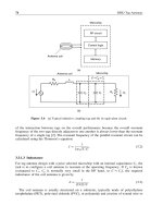
A simple small antenna is shown in Figure 2.1, where a short monopole is fed against a
groundplane. This antenna looks capacitive all the way from DC to the frequency at which
it is almost /4 long. The input impedance has the form Zin = R +jX, where R is small
and X is very large. The bandwidth will be limited by the Q of the device, where Q = X/R.
If the antenna is a very small fraction of a wavelength long, it is necessary to excite a
very large current in it to persuade it to radiate any significant power; put another way,
its radiation resistance is very small so it must carry a large current to radiate the required
power. Unfortunately the radiation resistance may be comparable with the loss resistance
in its conductors and the equivalent loss resistance of any insulating components needed to
support it. We are therefore confronted with a very small bandwidth and a problem with
efficiency – any current will create losses as well as radiation. The efficiency will be
limited to a value given by R
r
/R
l
+R
r
where R
l
is the equivalent loss resistance and R
r
is the radiation resistance. To feed energy into the antenna we will need to match it to a
transmission line, and the matching circuit will contribute further losses.
Figure 2.1(a) shows a short vertical radiator over ground – for the moment we can regard
this as perfect ground. The current at the top of the radiator is zero and it rises linearly to some
maximum value at the bottom (it is approximately linear because although the distribution is
approximately sinusoidal, sin ≈ when is small). We can improve matters by extending
a horizontal conductor from the top of the antenna (Figure 2.1(b)); this occupies no more
height but the current zero is now moved to the ends of the horizontal sections and a larger
and almost constant current flows in the vertical section. We have increased the radiation
resistance (R
r
) and at the same time reduced the capacitive reactance X
c
at the feedpoint, so
the Q of the antenna has fallen. Figure 2.1(c) shows an alternative configuration with similar
characteristics, known as an inverted-L antenna. In both cases the top conductor contributes
little radiation because of the proximity of its anti-phase image in the groundplane.
(a) Simple vertical radiator
(b) T antenna
(c) Inverted-L antenna
Figure 2.1 Short radiators over ground.
16 Handset Antennas
(a) Folded inverted-L
(b) Tapped inverted-L – an inverted-F
(c) Planar inverted-L antenna
(d) Planar inverted-L antenna with a
folded top
Figure 2.2 Derivatives of an inverted-L.
To further increase the value of R
r
we can fold the antenna as in Figure 2.2(a), or tap it in
the manner shown in Figure 2.2(b) – an inverted-F antenna. This will be naturally resonant
when the total length of the upper limb is around /4, and by selecting the position of the
feedpoint the input impedance can be chosen to be close to 50 ohms.
We can replace the wire top of the inverted-L with a plate (Figure 2.2(c)) and slot the
plate to make the loading more compact (Figure 2.2(d)). Unfortunately we have still not
overcome the constraint created by the small volume of the antenna and we need another
trick to allow us to solve our problem. An important feature of all these configurations is
that they are unbalanced. If we conceive the ground as an infinite perfect conductor we can
envisage an image of the antenna in the groundplane and calculate the radiation pattern by
summing the contributions of the antenna and its image.
When we build one of these antennas on a handset, the groundplane is only around /4
long – about the same length as one half of a dipole. What we have created is a kind of
curiously asymmetrical dipole; one limb comprises the groundplane of the handset, while
the other limb is the F-structure we have fed against it. What properties might we expect of
this configuration?
Polarization. The polarization of the inverted-F antenna (Figure 2.2(c)) is vertical – orthog-
onal to the groundplane. We can envisage this from the direction in which we apply the
feed voltage, the current in the vertical radiating leg and the alignment of the E-field
between the top and the ground. By contrast, our asymmetric dipole is polarized in the
direction of its long axis, along which most of the radiating current flows.
Radiation patterns. The inverted-F antenna would have an omnidirectional pattern in the
plane of the ground, while the asymmetric dipole would be omnidirectional in the plane
bisecting the groundplane.
If we now examine the behavior of a typical handset we see that it really does have
these properties. The antenna has very little relationship to the prototypes from which we
derived it. The polarization is aligned with the long axis of the phone, and its radiation
pattern in the low bands looks very much like that of a half-wave dipole aligned with the
groundplane (see Figure 2.11 below).
2.3 Electrically Small Antennas 17
Bandwidth. The derivation we have followed makes it unsurprising that we can obtain a
far greater impedance bandwidth than would have been possible from the tiny structure
we usually refer to as the antenna (and which we can now recognize as being some
kind of coupling structure whose main purpose is to allow us to excite currents in the
groundplane). Not surprisingly the largest bandwidth will be obtained when the phone is
of a resonant length, as in this event the impedance presented to the currents flowing into
the groundplane will change less rapidly with frequency [14].
High-band performance. In the high bands the antenna is electrically larger and we could
expect that it might operate more independently of the groundplane. In fact the polarization
usually remains along the groundplane and the radiation pattern simply looks like that of
a long dipole driven from a point off-center (see Figure 2.12 below). A small antenna
can provide adequate high-band performance, and we shall later examine the possibility
of making a balanced antenna operating substantially independently of the groundplane.
The chassis of the handset. What has been referred to as the groundplane comprises all those
parts of the handset that are connected to the groundplane, including the battery, display,
case metallization and screening cans. For a two-part handset (clamshell or slide-phone)
it will comprise the grounded parts of both components.
Losses. An ideal antenna will radiate all the energy supplied to it. In practice losses are
created by:
•
Reflection caused by the mismatch between the antenna and its feedline. The reflection
loss is a major cause of inefficiency; it increases if the antenna VSWR rises when the
handset is held or placed against the head.
•
Absorption by circuits and other components inside the handset. RF energy may be
coupled into the drive circuits for loudspeakers, cameras and other components if
they are close to the antenna and exposed to RF fields. This coupled energy will not
contribute to radiation from the handset.
•
Absorption by flexi-circuits connecting various handset components. Although these
are not close to the antenna they can contribute losses by coupling energy into internal
circuits.
•
User effects. The user’s hand and head change the antenna VSWR, absorb RF energy,
and may block the potential propagation path between the handset and the base station.
•
Dissipation within the antenna. Dissipation of RF energy within the antenna is relatively
much less important than most of the other effects.
The demands on mobile phone performance have increased rapidly over the last few
years. The economics of manufacture makes it very desirable to make handsets that cover
several of the increasing number of world frequency bands. For high-end products both
economics and user expectations require them to cover as many bands as possible. Currently
at least five bands are assigned for world-wide mobile services (850, 900, 1800, 1900 and
2100 MHz), so many antennas must cover 824–960 MHz and 1710–2170 MHz with high
efficiency. Not only must the bandwidth of the antenna be very wide, but modern large color
displays are power-hungry and place heavy demands on battery life. When transmitting data
using high-order modulation schemes such as EDGE (enhanced data rate for GSM evolution)
and HSDPA (high-speed downlink packet access), it is very important that handset antenna
gain and efficiency are as high as possible. If the received signal level is too low, the base
18 Handset Antennas
station will raise the handset power level and request retransmission of blocks of lost data;
this will consume additional network resources (additional coding is added, so the time
taken to transmit a given amount of revenue-earning data is extended) and demand longer
transmission times at high power from the handset, discharging the battery much faster than
would have been necessary had the antenna performed better.
Additional pressure is placed on the antenna designer by the shrinking size of handsets,
the increased competition for physical space in the handset – the user wants a camera and
a music player, not an antenna – and the power demands of the latest hardware and games.
The handset may provide other services that require antennas – for example, GPS position
fixing, Bluetooth
™
or wireless local area network (WLAN) connectivity, and radio or TV
entertainment services. Antennas for these services compete for physical space and it is
necessary to avoid unwanted interaction between the electronics supporting the different
services.
2.4 Classes of Handset Antennas
Large numbers of alternative handset antenna designs can be found in the technical literature
and a useful summary is provided in [14]. There are relatively few basic designs, but each
has many variants. A convenient method for reviewing the basic designs is to examine their
history over the period of development of modern mobile radio systems. Designers should
be aware that many configurations are the subject of current patents.
Whip antennas. A quarter-wavelength whip or blade mounted on a large handset provides
efficiency which still forms the standard by which other antennas are judged. Unfortunately
low-band whips are inconvenient: they typically have to be extended or folded up when the
phone is in use and the moving mechanical parts are costly and become worn or broken.
Pull-out whips need careful attention to the design – many of these antennas can be pulled
out of the handset by a sharp tug and cannot be refitted correctly without dismantling the
handset. Hinged blades are vulnerable to damage in both stowed and operating positions.
Meanders and coils. To make whips more acceptable to users, the simple straight conductor
is wound into a helix or meandered so the quarter-wave conductor is contained in a short
housing, often designed to be flexible.
Dual-band whips and coils. The progressive introduction of a second tier of mobile services
in the high bands quickly led to requirements for dual-band handsets. These allowed
users to roam between networks operating on different bands, created the possibility of
overlay/underlay dual-band network configurations and provided economies of scale in
handset manufacture. The commonest early designs comprised whips fed by a coupling
structure, but these have been replaced in most markets by dual-band concentric helix-whip
and non-uniform helical structures [15], both of which were externally similar to their
single-band predecessors. These remain standard external antennas but in many markets
users increasingly choose handsets with internal antennas.
Early internal antennas. One of the earliest forms of internal antenna was a meandering
conductor etched on the main printed circuit board (PCB), often configured as a form
of T or inverted-L antenna. The addition of shunt-feeding to the inverted-L created the
inverted-F antenna (IFA) which has become a classic standard form of internal antenna. In
the planar inverted-F antenna (PIFA) the upper loading wire of the conventional inverted-F
becomes a flat plate (Figure 2.2(c)).
2.4 Classes of Handset Antennas 19
Dual-band internal antennas. The frequency assignments for the low and high bands are
about an octave apart, so it is not easy to provide an acceptable input VSWR using a
single internal element. The standard solution is to use two radiating elements fed in
parallel at their common point. This principle can be applied to monopoles and to PIFAs
[16]. In both instances the short (high-band) element creates a capacitance in parallel with
the lower impedance of the resonant (low-band) element, while at the high band the long
element has a high impedance and most of the power is radiated by the short element
which is approximately a quarter-wavelength long.
An alternative hybrid antenna is shown in Figure 2.22(c). below the whole length of the
conductor operates on the low band as a folded-up monopole, while at the high band
the antenna acts as a half-slot. The input impedances in both bands depend on the same
dimensions, making this format tricky to optimize.
Triple-, quad- and penta-band antennas. The growth of world-wide mobile services has
seen a progressive increase in the number of frequency bands that must be supported by
a handset. For a quad-band or penta-band antenna, the low-band response must range
over 826–960 MHz (15.3%) and that of the high band over 1710–2170 MHz (24%). These
bandwidths far exceed those of the early dual-band antennas.
Multiple antennas. Techniques such as dual-antenna interference cancellation (DAIC) require
the provision of a second receiving antenna [17]. The challenge is to find room for this
second antenna and ensure that neither antenna is blocked by the user’s hand. Use of
DAIC on a single band is relatively simple but extension of this technique to multiple
frequency bands requires a second broadband antenna.
Multiple-input, multiple-output (MIMO) schemes. These exploit multipath transmission to
enhance the available data rate. Multiple signal samples are transmitted and the data stream
is reassembled after being received by multiple independent receiving antennas [18].
Additional services. At the upper end of the market, handsets are becoming ubiquitous
terminals for communications, information and entertainment. This is driving requirements
to add antennas capable of supporting GPS, WLAN, Bluetooth
™
and DVB-H, VHF and
later medium/high frequency digital radio, Band II analog FM, DAB (Digital Audio
Broadcasting) and DRM (Digital Radio Mondiale). The antenna designer must not only
create new designs capable of providing these facilities but also manage the interactions
that can limit their usefulness. This represents a major challenge.
A common characteristic of the antennas described above is that they are unbalanced. In
each case the antenna is driven from a single terminal on the handset PCB.
There are two different approaches to placing an antenna in a handset – the groundplane
can be left in place under the antenna or removed (Figure 2.3). If the groundplane is left in
place the most critical dimension is the height h available above the groundplane. Designs
with no groundplane under the antenna suffer less restriction on the thickness of the handset,
but the PCB length must be extended to accommodate the antenna and no components can
be mounted on the opposite face of the board. While the size of on-groundplane designs can
be compared in terms of the volume occupied by the antenna, it is not easy to compare on-
and off-groundplane designs in this way. This can lead to an impression that off-groundplane
designs are smaller, but the volume they effectively deny to other components may be large,
and the additional length they require may be unacceptable.
20 Handset Antennas
h
No significant keep-out zone
Keep-out zone
Antenna
Antenna
Figure 2.3 On the left the antenna is mounted over the groundplane; on the right he groundplane has
been completely removed under the antenna but components can no longer be mounted underneath the
end of the PCB.
2.5 The Quest for Efficiency and Extended Bandwidth
In the quest for increased operating bandwidth we are constrained by two main parameters,
the dimensions of the handset chassis and the permitted size of the antenna. As we noted
in Section 2.3, the behavior of small unbalanced antennas is strongly dependent on the
dimensions of the groundplane. Figure 2.4 shows the typical relationship between the avail-
able impedance bandwidth and the length of the groundplane (see also [14]). The absolute
bandwidth depends on the design of the antenna and the width of the chassis – it is generally
slightly greater if the chassis is wider, and the length for optimum efficiency is reduced.
In the example shown, the VSWR bandwidth available with a chassis length of 120 mm is
double that for a length of 90 mm.
Handset antenna bandwidth as a function of chassis length
0
2
4
6
8
10
12
14
16
18
20
50 75 100 125 150 175 200
Chassis length (mm)
Bandwidth (%)
Bandwidth (%) (RL > 3dB)
Bandwidth (%) (RL > 6dB)
Bandwidth of
GSM
900 band
Figure 2.4 Typical relationship between antenna impedance bandwidth of a 900 MHz PIFA antenna
mounted on one end of a handset chassis and the length of the chassis.
2.5 Efficiency and Extended Bandwidth 21
2.5.1 Handset Geometries
The relationship in Figure 2.4 applies to a single-component handset, often referred to as
a bar (or candy-bar) phone. Matters are more complicated when the handset has a variable
configuration. Clamshell phones comprise two components joined by a hinge, so the antenna
must operate efficiently in open and closed configurations – some variants have a complex
hinge allowing two axes of rotation which effectively adds a third operating configuration.
Slider phones comprise two separate components placed with their large faces together,
connected with a slide mechanism. These are used in open and closed configurations.
Other geometries have appeared, but none has been adopted on a significant scale. These
include handsets with the two components hinged on the long side like a small diary, and
handsets which can be opened along either the long or the short edge (three operating states).
The requirement to operate with full efficiency in both open and closed configurations was
not so significant with early handsets because they were normally opened for use. Lower
efficiency was acceptable in the closed condition; in this state they only needed to respond
to network control messages and ringing – both of which are well protected against poor
efficiency by lower code rates. Modern handsets must retain the greatest possible efficiency
when closed because many are capable of use for voice calls when open or closed. Large
incoming data volumes may be handled when the handset is closed, possibly when the
handset is in the user’s pocket, purse or belt pouch.
2.5.2 Antenna Position in the Handset
For each handset geometry there are several possible antenna positions. Each geometry and
position creates a different set of challenges for the antenna designer in terms of the available
shape and volume, the proximity to other components likely to interact with the antenna,
and the ability of the antenna to excite radiating currents in the chassis.
Barphones almost universally have their antennas located at the upper end of the handset,
above or behind the display. This position uses the whole length of the chassis to achieve
maximum bandwidth. If the handset is more than about 90 mm long and has the right ‘feel’
in the hand, the user will hold the lower part of the phone and the antenna will not be
covered when the handset is held to the ear. Shorter barphones tend to be held with the hand
covering most of the rear surface, so the antenna may be completely covered by the user’s
hand. Some handsets have a sticker suggesting: ‘Keep your fingers away from the antenna’,
but this is likely to be quickly taken off by the user and the message forgotten.
Clamshell phones do not have a universal position for the antenna and three different
locations are used (Figure 2.5):
(a) Top of the flip. Although occasionally used, this is not a very satisfactory position from
the antenna performance point of view.
•
The flip is usually thin – often only 5 mm, including the thickness of the case.
•
The area round the antenna may not be well grounded.
•
The antenna competes for space with the loudspeaker.
•
The PA is usually positioned on the main PCB so an interconnecting coaxial cable
is required, usually with at least one demountable connector. This is an expensive
22 Handset Antennas
Figure 2.5 Typical antenna positions in a clamshell handset. A variant of the hinge position allows
the lower part of the handset that contains the antenna to extend beyond the hinge (right).
arrangement that complicates the mechanical design of the hinge which must accom-
modate both a flexible PCB (FPCB) driving the screen and a coaxial cable.
•
If the groundplane is removed the antenna is very close to the user’s ear, so the SAR
may be high.
(b) End of the main component of the handset, adjacent to the hinge. This is the usual
position. The antenna is usually clear of the loudspeaker, but the position suffers a
number of disadvantages.
•
When held to the ear in the open position, the handset is often held near the hinge
and the user’s hand covers the antenna.
•
When closed, the antenna lies at one end of the handset but when open the antenna
position is close to its mid-point. This change in relative position leads to a large
change in impedance characteristics when the phone is opened and closed.
•
The hinge accommodates flexible connections between the display, camera and
processor. The flexi-circuit is excited by RF fields close to the antenna, leading to
loss of RF energy, and the high-frequency digital signals in the flexi-circuit radiate
noise over a wide spectrum, desensitizing the receiver, particularly in the low bands.
It will be seen from Figure 2.5(d) that when the lower component of the handset is
extended past the hinge this position is very similar to that of a typical short helical
external antenna in a clamshell handset.
(c) Lower end of the main component of the handset. This position is generally clear of
hand cover when the handset is open and in use for voice calls. Other advantages of the
lower end position are:
•
The antenna is well-separated from the FPCB at the hinge.
•
The antenna does not have to share space with the speaker.
2.5 Efficiency and Extended Bandwidth 23
•
The antenna is not close to the head or to any hearing aid worn by the user – only the
(inevitable) radiation fields interact with the user’s head, not the local stored-energy
fields associated with the antenna.
•
The antenna is positioned at the end of the handset in both open and closed states –
this makes the change in antenna impedance between the two states more manageable.
Slider phones typically have the configurations and antenna positions shown in Figure 2.6.
The slider configuration is relatively uncommon, so the design can be regarded as rather
less mature than the barphone and clamshell. The lower component of the handset usually
contains the keyboard and RF components while the upper component contains the camera
and display. The two typical antenna positions are:
(a) Top end of the lower component – under the display when the handset is closed. This is
the most common position. The groundplane usually extends over the antenna, limiting
the extent to which the local fields of the antenna interact with the upper component
when the handset is closed. Interaction with the speaker is limited because it is usually
housed in the upper component. Slider phones can only be made thin if both components
are thin, so there is always great pressure on the available height for the antenna. The
antenna is at the end of the handset in the closed position but is about a third of the way
down the handset when it is open. This creates a large difference between the open and
closed antenna input impedances.
(b) Bottom of the lower component (under the keypad). Although this is a less common
position, it has the advantage that the antenna is at the end of the handset in both
open and closed positions. The antenna is also in a low-noise area of the handset, well
separated from the potentially noisy camera and display.
2.5.3 The Effect of the User
There is strong interaction in terms of handset efficiency between antenna position and user
grip – the way users typically hold their handsets while making calls or using the handset
for interactive data, Web browsing, playing games and writing text messages. Modes of grip
which cover the antenna with the hand are likely to have high hand losses compared with
those which leave the antenna uncovered. Careful observation of users clearly shows that
many common assumptions in this respect are not accurate. A sample of several hundred
Japanese users of clamshell handsets showed that almost all used their handsets to access
data (perhaps checking the times of their trains or letting their families know they were on
their way home) by hooking their index finger round the upper end of the handset body
(where the antenna is usually located) and operating the keypad with the thumb of the same
Figure 2.6 Typical antenna positions on slider phones.
24 Handset Antennas
hand. The natural grip for a handset depends on its shape and feel, and the effect of the
user on the antenna depends strongly on its position relative to the hand. These are features
determined by the industrial design (ID) of the handset and not by the antenna designer.
This implies that by the time the antenna designer receives a prototype handset some very
important limits have already been set on its potential performance. Users will hold the
handset in the manner that feels natural to them; the industrial designer must understand and
use this to try to ensure that the antenna remains uncovered when the phone is in use.
During voice calls users may modify their grip in the event that the perceived audio
volume is too low or there is a high level of local acoustic noise. Their grip may also be
changed if the perceived audio quality is poor. The handset is often pressed closer to the ear
and the user’s hand may be cupped round the top of the handset in an effort to hear more
clearly. This often results in covering the antenna and further reducing the signal. In data
modes the user will not generally have much feedback about signal quality and no significant
feedback mechanism will apply.
2.5.4 Antenna Volume
There is an unavoidable connection between the physical volume of the antenna and the
bandwidth that can be obtained. This may be regarded as an expression of the Chu-Harrington
limit, but it is probably better seen as describing the effectiveness of the antenna structure
in driving radiating currents in the chassis of the handset. The relationship may be seen in
two ways: for a given antenna volume there is a minimum chassis length that is necessary to
provide a certain bandwidth; for a given chassis length there is a certain minimum antenna
volume that can provide the required bandwidth. Handsets that have both small length and
a small available volume present a particular challenge to the antenna designer’s ingenuity.
Once the ID has been fixed, the maximum efficiency that can be obtained has also been fixed;
suboptimal antenna and circuit design will lead to the achievement of some lower efficiency,
but the maximum was determined by the ID. The relationships between dimensions and
bandwidth for a barphone are indicated in Figures 2.7–2.9.
2.5.5 Impedance Behavior of a Typical Antenna in the Low Band
In discussing the optimization of the impedance bandwidth of an antenna it is useful to be
able to refer to the behavior of the input impedance by some convenient shorthand terms. We
will define these by reference to a typical standard PIFA (Figure 2.10). If the feed position
is close to the short circuit the input impedance has the characteristic behavior shown in
Figure 2.10(a). The impedance plot remains close to the edge of the Smith chart at most
frequencies, with a small circle at the frequency at which the antenna is resonant. This will
be referred to as an under-coupled response. As the input position is moved away from the
short circuit, the size of the circle indicating the resonant frequency grows until at some
point it passes through the center of the Smith chart (50 +j0 ohms), a situation which we
will refer to as critical coupling (Figure 2.10(b)). As the feedpoint is moved further from
the short circuit the size of the resonant circle continues to grow and we will refer to this
state as being over-coupled (Figure 2.10(c)). We can separately control the coupling and
the resonant frequency by using two parameters, the distance between the feedpoint and the
2.5 Efficiency and Extended Bandwidth 25
0.0
50.0
100.0
150.0
200.0
250.0
70 75 80 85 90 95 100 105 110 115 120
PCB Length [mm]
htdiwdnabevitaleR
-3dB BW
-6dB BW
Figure 2.7 Relationship between length and bandwidth at 1850 MHz. For the low-band relationship
see Figure 2.4.
0.0
20.0
40.0
60.0
80.0
100.0
120.0
140.0
160.0
4 5 6 7 8 9 10 11
Antenna Thickness [mm]
annetnaecnerefer.t.r.
wWBfo%
-3dB BW
-6dB BW
Best fit trendline (-6bB)
Best fit trendline (-3bB)
Figure 2.8 Relationship between bandwidth and antenna height at 890 MHz.
26 Handset Antennas
0.0
25.0
50.0
75.0
100.0
125.0
150.0
175.0
200.0
225.0
4567891011
Antenna Thickness [mm]
annetnaecnerefer.t.r.wWBfo%
-3dB BW
-6dB BW
Best fit trendline (-6bB)
Best fit trendline (-3bB)
Figure 2.9 Relationship between bandwidth and antenna height at 1850 MHz.
(a) (b) (c)
Figure 2.10 Typical feed positions and impedance plots for a PIFA: (a) under-coupled; (b) critically
coupled; and (c) over-coupled.
2.5 Efficiency and Extended Bandwidth 27
short circuit and the overall length of the top of the antenna – this is true whether the top is
in a straight line or is convoluted in some way.
We will return to a discussion of the construction of the antenna in Section 2.6, but the
dominant influence of the handset configuration and dimensions suggests that we should
examine these first. When we examine a handset to see whether it will be possible to
provide the required antenna functionality, the most important considerations are the size
and geometry of the handset and the volume and position available for the antenna. If these
have already been determined, the antenna designer will need to use considerable diplomacy
in persuading others that the necessary performance may be simply impossible to achieve
without changes to the design of the handset.
2.5.6 Fields and Currents on Handsets
One of the most useful features of computer programs for electromagnetic simulation is that
they help in the visualization of radiating currents and fields. They allow us to develop an
understanding of the mechanisms underlying the behavior of antennas on handsets and to
develop strategies for the optimization of bandwidth and efficiency.
Figure 2.11 is a simulation result for a conventional PIFA placed at the end of a simple
rectangular groundplane 100 mm long [19]. It shows the electric field that exists on a plane
slightly displaced from the axis of the groundplane, which can be seen immediately below
the simulation plane. The displacement of the simulation plane avoids displaying the local
fields around the antenna and allows us to see the fields that are contributing to radiation –
without the clue of the input connector (below the groundplane on the right) it would be
difficult to identify the location of the antenna, so this simulation emphasizes the way in
which the groundplane contributes a dipole-mode field. Unsurprisingly the corresponding
far-field radiation pattern is very similar to that of a half-wave dipole (Figure 2.11(b)).
It is more surprising that the same relationships hold at the high bands, but again the
unbalanced feed for the antenna results in dominant fields being produced by the chassis
(Figure 2.12). The radiation patterns are similar to those of a long dipole with an asymmetric
Type
Monitor
Component
Plane at z
Frequency
Phase
Maximum-2d
= e-field (f = 920) [1]
= E-Field (peak)
Farfield ‘farfield (f
= 930) [1]′ Gain_Abs(Phi); Theta = 90.0 deg.
90
120 60
30150
180 0
–10 –5 0
5
330210
Frequency
Main lobe magnitude
Main lobe direction
Angular width (3
dB)
= 930
= 0.9 dB
= 10.0 deg.
= 91.1 deg.
240 300
270
= Abs
= 15.8074
= 920
= 202.5 degrees
= 645.076 V/m at 6.5 / 11 / 15.8074
(a) (b)
[dB]
Figure 2.11 Simulations of the E-field and radiation patterns of a typical barphone at 920 MHz.
28 Handset Antennas
Farfield ‘farfield (f = 1800) [1]′ Gain_Abs(Phi); Theta = 90.0 deg.
90
120 60
30150
180 0
–10 –5 0 5
[dB]
330210
Frequency
Main lobe magnitude
Main lobe direction
Angular width (3
dB)
= 1800
= 3.5
dB
= 324.0
deg.
= 53.2 deg.
Side lobe level = –5.3 dB
240 300
270
Type
Monitor
Component
Plane at z
Frequency
Phase
Maximum-2d
= e-field (f = 1800) [1]
= E-Field (peak)
= Abs
= 15.8074
= 1800
= 157.5 degrees
= 266.616 V/m at 6.5 / 5 / 15.8074
Figure 2.12 Simulations of the E-field and radition patterns of a typical barphone at 1800 MHz.
feed. At both bands almost identical field amplitudes and distributions are seen on both faces
of the chassis – again emphasizing its central role in the radiation process.
Not only do the simulated fields match the simulated (and measured) radiation patterns, but
it is quickly found that the impedance bandwidth available from an antenna depends critically
on the extent to which it excites currents in the groundplane. For a real handset the currents
will flow in the groundplane and all the grounded hardware connected to it, a configuration
which we will refer to collectively as the chassis of the handset. Repeated simulations using
different antenna and chassis parameters clearly show that any configuration in which chassis
currents are weak is likely to have a narrow impedance bandwidth. If the E-field is computed
on the groundplane itself, this effect is not seen very clearly because most simulation
programs rescale their output to accommodate the strong fields around the antenna. These
are intense local fields – for example, between the antenna and the groundplane – but their
effect at a large distance from the handset is not very significant. The universal rule is seen to
be that the larger the current the antenna can establish in the chassis, the more effective it is
as an antenna! If a simulation shows that a low-band antenna stimulates only small currents
in the chassis, its impedance inevitably changes rapidly with frequency. The antenna itself
has too small a size to be able to operate as a wideband antenna – the role of the device
we refer to as the ‘antenna’ proves to be that of a coupling device, stimulating radiating
currents in the handset chassis. In view of what we know of the bandwidth limitations of
small antennas, this explanation makes perfect sense!
This conclusion has several important consequences:
•
It is best to design and position the antenna with the objective of stimulating chassis
currents.
•
For a given radiated power, there is a necessary value of chassis current and resulting
local E- and H-field. Any local effect of this radiating current is an inevitable consequence
of the absolute power radiated.
These are very significant conclusions. We have noted that the radiating fields on the opposite
side of the chassis to the antenna are very similar to those on the face containing the antenna,
so undesirable effects caused by electromagnetic fields in the region of the user’s head
can be reduced only by radiating less power or by reducing the interaction between the
2.5 Efficiency and Extended Bandwidth 29
local fields surrounding the antenna. The most obvious precautions are to place the antenna
on the opposite side of the groundplane to the user and to position the antenna so it will not
be close to the user’s head when the handset is in use. Interference with a hearing aid worn
by the user will be reduced by the same precautions.
2.5.7 Managing the Length–Bandwidth Relationship
The relationship between dimensions and the ability of the antenna to excite chassis currents,
essential for low-band performance, now has to be understood in the context of the wide
variety of handset geometries and antenna locations encountered in practice. To emphasize
that the radiation efficiency is governed by a complex interaction between the antenna and
the handset, the term handset efficiency is used here in preference to the more usual term
antenna efficiency.
2.5.7.1 Barphones
Most barphones are shorter than the length that provides the largest possible bandwidth
(about 115 mm) so, from the point of view of both bandwidth and the convenience of laying
out the components of the rest of the handset, it is usually advisable to mount the antenna at
the end of the handset.
The provision of high efficiency across both the low bands is almost always challenging,
but when the chassis is less than about 80 mm long it rapidly becomes difficult to provide
a satisfactory return loss and efficiency across either the 850 MHz or the 900 MHz band. In
this situation it is useful to position the antenna feedpoint at one corner of the main PCB (or,
to put it another way, to drive the main PCB from one corner). This effectively increases the
chassis length to the dimension of its diagonal. It also creates the typical skew in the axis of
the radiation pattern seen in Figure 2.11.
With very short handsets it may be necessary to create some form of artificial extension to
the length of the chassis, for example by adding a flange or slotted flange at the end remote
from the antenna (Figure 2.13). This is a well-known technique seen in commercial handsets.
Adding a flange may be compared with capacitively loading the ends of a short dipole.
Additional measures can be taken to make the added section appear to be electrically longer
than its physical length, but this may be at the expense of frequency bandwidth – it may
allow the handset to operate better at the bottom of the band, but may inhibit its performance
at other frequencies. Methods involving inductive notches cut in the groundplane are also
possible, but they may limit unacceptably the layout of other components on the PCB –
already difficult on a very short board.
The result of adding length in this way will not be as effective as if the chassis had the same
overall length in one plane, but the advantage obtained may be sufficient to provide a small
but critical increase in low-band efficiency. Adding further inductive or capacitive loading
within the extended structure is also sometimes useful, but this is a process of diminishing
returns – if the loading is itself resonant, then its effective bandwidth is reduced and its
interaction with the resonant behavior of the whole chassis may not produce the expected
result. At frequencies lying between various resonances the efficiency of the handset may
be lower than expected.
30 Handset Antennas
Figure 2.13 A short chassis can be extended by fitting a conducting extension, folded (along the
dashed line) against the far end of the case.
2.5.7.2 Clamshell Phones
A typical clamshell phone is around 80 mm long when closed and 140 – 160 mm long when
open. The relationship between the open and closed lengths depends on whether the flip
and the body of the handset are of equal length (the flip is often shorter than the body) and
also the position of the hinge (see Figure 2.5). Referring to Figure 2.4 we see that when
closed the chassis length is less than that required for optimum bandwidth, and when open
it is too long. In both configurations the length is far from the optimum and bandwidth is
restricted. A measurement of the antenna impedance in both open and closed positions will
generally show a very large change in the antenna coupling (Figure 2.10) as well as a change
in the resonant frequency. It is difficult to achieve optimum return loss (and efficiency)
performance in both open and closed states – to achieve this objective we need to identify
design parameters that, as far as possible, separately control the antenna impedance when
the handset is open and closed.
The reason for this impedance change is clear: the configuration of the (radiating) chassis
has changed and the position of the antenna relative to the positions of current maximum
on the chassis has also changed. We can improve matters to some extent by adopting a
compromise antenna design (in which the coupling and resonant frequency take values on
either side of the optimum in the two states). Typically performance is weighted toward the
open state on the basis that voice calls and Web browsing will only take place when the
handset is open, but this may not apply if the handset can be used for voice calls or for
transmitting pictures when it is closed. Increased functionality has not only increased pressure
on handset efficiency in general, but demands similar efficiency in all states of the handset.
The Open Clamshell
Figure 2.14 shows a simplified view of a clamshell handset with the antenna placed at the
lower end of the main component. The two components are connected by a flexi-circuit
whose function is to provide DC and data connectivity to the display, camera, speaker and
other components mounted in the flip. The physical form of the connection varies, but it
typically consists of several layers of FPCB with at least one layer having a continuous
ground conductor on one face. The points of connection in the handset components are
usually close to their adjacent ends, but are sometimes as far as 25 mm from the ends. The
flexi-circuit is shaped to fit through a channel provided in the hinge and is usually looped
around the hinge axis to ensure that the movement of the hinge causes it to bend in the
2.5 Efficiency and Extended Bandwidth 31
Antenna
Main Flip
Stray C
Flexi-
circuit
(a)
(b)
s
1
s
2
Figure 2.14 (a) The effective RF configuration of an open clamshell handset. (b) The overhangs of
the components beyond the connection points.
desired plane. Any tendency to twist or bend in the plane of the circuit must be avoided or
it will rapidly fail in use. When opened flat, a typical hinge FPCB is between about 50 mm
and 80 mm long, measured along the ground conductor, and about 6 mm wide.
From an RF standpoint the flexi-circuit provides an inductive connection between the two
components with an inductance determined by its length and configuration. The net reactance
between the two components depends on the values of the series connecting inductance
(L
s
) and the shunt capacitance (C
p
) which is created by the geometries of the hinge and
flexi-circuit. If the two reactances are parallel-resonant in the lower band, the effective
length of the open handset will be that of the main component; if they are non-resonant,
the effective length will be that of the entire length of the open handset loaded by the
series reactance between them. Figure 2.15 shows a simulation of the surface currents in
Type
Monitor
Component
Plane at x
Frequency
Phase
Maximum-2d
= e-field (f = 944) [1]
= E-Field (peak)
= Abs
= 41.8075
= 944
= 45 degrees
= 349.694 V/m at 41.8075 / 8 / 0.05
Type
Monitor
Frequency
Phase
= h-field (f = 944) [1]
= Surface Current (peak)
= 944
= 292.5 degrees
Maximum-3d = 147.502 A/m at 27 / 1 / –0.9
Figure 2.15 A closed clamshell handset with the connecting flexi-circuit modeled as a simple mean-
dered link showing (a) the E-field on a plane displaced to fall just outside the handset and (b) the
currents in the chassis.
32 Handset Antennas
a simplified clamshell handset. The connection supports a current almost as large as that
flowing in the PIFA antenna; this increases the importance of the value of the reactance
in which it is flowing (if the connection lay at a current minimum its value would be less
significant). Fortunately we can manage the effective electrical length of the open handset
by adjusting the net reactance across the hinge. This parameter, vital to the RF performance
of the handset, is only adjusted by close co-operation between the antenna engineer and the
industrial and mechanical designers. We can understand the significance of both L
s
and C
p
by examining some extreme cases:
1. If L
s
is very small it requires a large value of C
p
to bring it into resonance and the rate
of change of reactance with frequency around resonance is large. The exact value of C
p
is also very critical.
2. If L
s
is very large it may already be self-resonant or it will require only a very small
value of C
p
to bring it to resonance. The net reactance is likely to be capacitive and is
difficult to change.
3. If C
p
is very large the net reactance is small and capacitive whatever the value of L
s
.
4. If C
p
is very small the reactance is dominated by L
s
and the effective handset length is
too long.
The best situation is that in 4, because we can gain control of the connecting reactance
by deliberately increasing C
p
to a value chosen to be sufficiently close to resonance to
deliver the greatest available bandwidth. In practice it will be found that this occurs when
the net reactance approaches resonance from the capacitive direction. Depending on the
effective value of L
s
the optimum value of C
p
may be extremely critical (to within a
few picofarads). In general terms L
s
is determined by the overall length of the connecting
FPCB (measured along the RF current path) and the position and alignment of the ends
of the connection relative to the ends of the components (s
1
and s
2
in Figure 2.14). C
p
is
determined by the geometry of conducting components in the area of the hinge and the
dimensions s
1
and s
2
. If the hinge design results in the two ends of the flexi-circuit passing
close to each other with facing flat faces, perhaps close to the exit point from the hinge,
this will create a very large value of C
p
which will be difficult to reduce. As s
1
and s
2
are
increased the length of the connection (and its inductance) inevitably increases; the regions
in which the connections pass over the groundplanes form transmission line stubs that further
increase L
s
.
The antenna designer can generally simulate the connection with sufficient accuracy to
gain some insight into the likely net reactance and the RF operation of the handset. The ideal
solution is to allow some later optimization, perhaps controlling the hinge capacitance by
adjusting the configuration of the conducting surfaces around it. An all-metal handset case
is likely to cause severe problems!
The Closed Clamshell
The radiating currents on a closed clamshell handset are seen in Figure 2.15(a) where the
antenna position is at one end. Once more the dominant field mode, seen in a plane displaced
so it falls just outside the handset, is a dipole mode with high fields and minimum currents
at the ends and maximum current in the center. If we move the simulation plane we also see
a current flowing along the folded chassis in the mode typical of a short-circuit stub. The
2.5 Efficiency and Extended Bandwidth 33
antenna impedance and its bandwidth will be determined by the impedances encountered
by the radiating (chassis) current mode, the transmission line current mode and the antenna
currents. If the net connection impedance was optimized for the open position, we must
use other methods to adjust the closed antenna impedance with the objective of ensuring
minimal change between the open and closed states. This suggests that we should examine
the effect of the transmission line current in the stub formed between the components. This
has a length determined by the geometry of the components, and a characteristic impedance
determined by the width of the chassis and the distance between the components in the
closed state. The capacitance across the open end of this stub has the greatest effect on the
antenna impedance and by optimizing the shapes and spacing of conducting components in
this region we can optimize the closed antenna impedance without significantly affecting the
open impedance.
This optimization is amenable to simulation, with physical adjustments made at the proto-
type stage to achieve optimum geometry.
The radiating modes for a hinge-position antenna are similar to those for the end-position
antenna. The main difference is in the effects of s
1
and s
2
, which modify the antenna
impedance in both states. The transmission line current may have a smaller value, but
the impedance it encounters is likely to vary more rapidly with frequency because the
transmission line stub is excited near its short-circuited end, producing a higher value of
loaded Q. These effects are best studied using simulation software, identifying the separate
and combined effects of the parameters involved.
Fortunately the effects of chassis length on antenna impedance are less marked (although
still significant) at the high bands. At regular intervals in the optimization of low-band
performance it is worth checking that high-band performance has not been compromised.
This is specially important when operation is needed over the whole range from 1710–
2170 MHz, when it may be difficult to recover high-band performance if the impedance plot
has spread too far across the Smith chart.
2.5.7.3 Slider Handsets
A slider handset typically has the configuration shown in Figure 2.6 The components are
physically connected together by a slide mechanism, usually containing both metal and
plastic parts, while electrical connection is made by a U-shaped flexi-circuit connected to
each component in the area that overlaps when the handset is open. This flexi-circuit is
typically 100 mm long and 15 mm wide and carries a large number of very fine traces
(perhaps 50) carrying digital signals to the display and camera, and audio signals to the
speaker. In a typical configuration ground conductors are provided along each edge of the
flexi-circuit, but these are very narrow and are not really of any use as RF grounds – anyway,
with a length of 100 mm they are ineffective irrespective of their width. The position of
the 180
o
U-bend moves along the flexi as the slide operates, so each station along the
central part of the flexi experiences a 180
o
flexure around a radius controlled by the handset
design every time the handset is opened or closed. Handset designers resist the suggestion
of providing a wide ground conductor because the small clearance between the components
requires that the flexi-circuit is bent with a very small radius and the repeated flexure causes
early failure of the conductor. The antenna excites a potential difference between the handset
components, and currents flow through the capacitance between them which is in parallel
34 Handset Antennas
Figure 2.16 A closed slider phone showing the very high field between the components.
with the effective reactance of the flexi-circuit. The lack of screening of the signal tracks
in the flexi results in RF currents flowing into other handset circuits where they contribute
only to losses and not to useful radiation. Figure 2.16 is a simulation result showing the very
high E-field existing between the components. Not only is this field trapped (raising the Q
of the handset) but it drives currents through the lossy flexi-circuit.
One method of reducing the RF currents in the flexi is to ensure that a large capacitance
exists between the components in both open and closed states [20]. This is easier to achieve
when the handset is open, when there is a larger facing area; in the closed state it may require
the provision of additional conductive areas on both components and connection of these
areas directly to the internal RF circuit grounds. (This is a parameter that suits an all-metal
handset.)
Given the provision of adequate inter-component capacitance, the main effect on antenna
impedance is that the length of the chassis changes between states. This is to some extent
offset by the fact that both components of slider phones are usually relatively long so the
severest effects of a short chassis are avoided. Antenna impedance is also affected by the
change in its relative position on the chassis when the handset is opened. This affects models
where the antenna is placed under the display, where the impedance responds to changes in
both length and relative antenna position. The under-keypad position is at the bottom of the
handset in both states, so the antenna impedance responds only to the length change.
Slider phones are relatively uncommon and will perhaps continue to be so as demand
increases for extra keypad functionality and larger displays.
2.5.7.4 Other Handset Configurations
A small number of handsets provide a hinge along the long axis of the handset. These
are usually not a major problem as they are long enough in the closed state to provide
reasonable antenna bandwidth. Some clamshells handsets have hinges that allow their flips
to be rotated while open. As well as creating a further geometry in which the handset must
operate efficiently, the more complex hinge geometry usually requires a longer flexi-circuit.
2.5 Efficiency and Extended Bandwidth 35
The use of more metal parts in the hinge to provide mechanical strength can result in a high
capacitance across the ends of the flexi, especially if the flexi is wound round a metal pin.
The loss of control of the inter-component capacitance almost inevitably leads to lower RF
efficiency as the antenna designer struggles to balance the conflicting demands of the three
operating states. Another variation is a compound hinge allowing operation in both long-edge
and short-edge opening – this provides the same potential challenges as the three-way hinge,
with a long flexi and metal hinge parts.
The continuing trend towards the integration of user functionality – mobile phone, camera,
PDA, audio and video player, and radio/TV capabilities – will drive the market to create
new hybrid device formats. These will be subject to huge constraints on dimensions and
weight. All the skill and ingenuity of the antenna designer will be needed to integrate the
necessary multiple antennas into a single compact device. New physical device formats will
appear and they will continue to influence the extent to which the desired RF performance
can be reliably achieved.
The transmission characteristics of signals at lower frequencies – in particular their reduced
diffraction loss round obstacles – make them attractive in rural areas and in other situations
where coverage is limited by transmission loss rather than capacity. The design principles
described in this chapter are applicable to any device in which antenna space is limited,
especially when the longest dimension of the device is small compared with the operating
wavelength.
2.5.8 The Effect on RF Efficiency of Other Components of the Handset
A number of the matters discussed below seem to be unrelated to antenna design, but it is the
antenna designer who is usually regarded as being responsible for the RF efficiency of the
handset and is probably best able and equipped to advise on these matters. If the potential
problems are not appreciated at an early stage of the design it becomes increasingly difficult
to persuade others of the need for change and the opportunity to correct matters is lost. The
handset will have poor efficiency and the antenna engineer will be seen as being responsible.
2.5.8.1 Loudspeakers
One of the most difficult aspects of design with barphones is the intensive use of surface area
and volume in the region at the top of the handset. It is common for the loudspeaker to be
placed close to or underneath the antenna. This always reduces the efficiency of the antenna,
although the extent of the reduction can be controlled by the positioning of the speaker,
choice of the speaker configuration, and appropriate isolation and decoupling to prevent RF
currents flowing into the audio circuit. Successful designs have been produced by using the
same physical structure to function as the acoustic resonator and the carrier for the antenna –
the loudspeaker is integrated into this assembly and is connected to pads on the supporting
PCB by spring pins. This design requires co-operation between the antenna designer and the
acoustic engineer who will specify the required volume, sealing and venting of the resonator.
Loudspeakers mounted close to antennas must have direct low-profile spring connections
(not wires) and be connected through inductors in series with both terminals. Some further
increase in antenna efficiency may be produced if the terminals are directly connected by a
bypass capacitor (typical value 10 – 30 pF). Speaker designs with some measure of external
36 Handset Antennas
screening to prevent direct inductive coupling of the RF fields to the speech coils are more
successful than designs with no screening.
The speaker is normally mounted against the groundplane, keeping as much clearance
between the speaker and the antenna as possible. An alternative strategy is to raise the speaker
above the groundplane and connect it with leads running down the antenna short-circuit.
2.5.8.2 Cameras
Careful attention must be given to the screening and grounding of cameras when they are
mounted in close proximity to antennas. Coupling of antenna fields into cameras and their drive
circuits will result in loss ofefficiency;couplingofcameradrive circuit currents into the antenna
may lead to increased receiver noise levels – a consideration that is particularly important if
the camera is to be used for video calls when the camera and receiver will operate together. A
screen wrapped round a camera module may have a length resonant in the high bands unless the
positions for its grounding to the main PCB are chosen with care – multiple ground points will
almost certainly be required.
A camera connected with a flexi-circuit and sited close to an antenna can be very destruc-
tive of antenna performance unless both the camera and the connecting flexi are well screened.
Checking the antenna impedance with the camera in various positions will allow the effective-
ness of the screening to be checked – and active measurements will confirm this.
RF currents, inevitably present in the hinge area of a clamshell handset at low band,
will couple into a poorly screened camera and its connections, reducing handset efficiency.
Cameras in the hinge itself are the most difficult to deal with, as their flexi-circuit may be
integral with the inter-component flexi; current densities in the ground conductor of this flexi
can be very large – not only is it in the high-current region of the middle of the handset, but
its restricted width increases the current density.
2.5.8.3 Vibrators
These are sometimes placed near antennas, but they often do not form good neighbors,
perhaps because of inadequate internal screening round the motor and its windings. The
off-center weight may not have a well-defined rest position.
2.5.8.4 Batteries
The battery occupies a significant proportion of the surface area of a handset – particularly
in a closed clamshell phone – and any disruption it causes the surface currents is likely to
result in changes to the antenna impedance and bandwidth. The case of a NiMH battery is
DC positive, while the groundplane of the handset is usually DC negative. This means that
the battery case – in which RF currents are likely to be induced – is connected directly to the
internal DC supply rail of the handset. From an RF point of view this is highly undesirable,
so precautions must be taken to adequately decouple the battery case. Decoupling usually
takes the form of series inductance in the DC connection and a bypass capacitor fitted
between the battery case and the handset ground. The case is grounded in this way at one
end, so the rest of the case forms a transmission line stub; the impedance seen at the open-
circuit end opposes the flow of currents in the surface of the handset chassis (Figure 2.17).
2.5 Efficiency and Extended Bandwidth 37
Z
b
Figure 2.17 The battery creates a transmission line stub creating an impedance in series with currents
flowing along the surface of the chassis.
This impedance will have least effect if it occurs at a point where the surface current is
smallest, so it is better for the battery connections to be provided at the inboard end and the
open circuit end to lie close to the end of the handset.
Further problems can arise if RF currents are allowed to flow into the static discharge
or charge control circuits; this possibility must be avoided by adequate isolation and
decoupling.
If the spacing between the antenna and the battery is too small the battery intersects the
local fields round the antenna. This causes strong excitation of currents in the battery case
and effectively restricts the volume available to the antenna. If the handset layout provides
inadequate clearance between the antenna and the battery it may be better to reduce the
antenna dimensions to increase the inadequate clearance.
In almost every instance the efficiency of a handset will be found to decrease when the
battery is fitted. This effect is almost avoidable if the matters indicated here are properly
managed.
2.5.8.5 Electromagnetic Compatibility (EMC) Shielding
In early handsets the entire inside surface of the case was covered with conductive paint; the
external antenna projected through a hole in this conductive enclosure whose purpose was to
provide an EMC (RF interference) shield for the handset. In many recent designs, shielding is
provided by metal cans placed over the susceptible components, but many handset designers
still use conductive paint as the last line of defense. It is the outermost conductive surface that
carries radiating currents on the chassis, so where EMC paint is used it forms the effective
radiating surface of the handset. EMC coating materials are of two types, lossy and highly
conductive. The paint should have high conductivity because any ohmic losses decrease
the power that will be radiated. The impact of surface currents on antenna impedance and
bandwidth mean that any EMC coating must be in place during RF testing early in the design
process or unexpected changes in RF performance may occur when the coating is applied.
The coating should form a closed box (avoiding the creation of any resonant structure that
can be excited by the radiating currents) and connections between the coating and the PCB
ground made with low-resistance gaskets. These both increase the shielding effectiveness of
the coating and also reduce losses where radiating currents flow from the coating to ground.
2.5.8.6 The Antenna Feed Circuit
It is important that low insertion loss and good impedance matching is maintained between
the PA (and the receiver input) and the antenna matching circuit. Any losses reduce the
power reaching the antenna. Frequency-dependent mismatch in the connecting lines will
make it difficult to obtain consistency of output power (TRP) over the operating frequency
38 Handset Antennas
band. The traces forming the RF connections must not pass over other internal lines unless
an intervening ground layer is provided and adequate vias must be provided along their
length to ensure that they do not excite unwanted modes between different groundplanes. As
much consideration must be given to the return (ground) path as to the outgoing stripline or
microstrip.
2.5.8.7 The Groundplane
An adequate groundplane must be provided over the whole length of the PCB. If this is not
done, RF currents will flow in other components such as the display and keypad and their
associated connections. These currents will encounter resistance and will consequently cause
RF power loss. The design of the bonding between handset components and the groundplane
needs to recognize the probability that RF surface currents will be present and they should be
provided with a low-resistance path in which to flow. Conductors forming loops will couple
to surface currents; where loops are formed deliberately – as in the interconnecting flexi-
circuit in a clamshell handset – they must be kept to minimum size, be stable in mechanical
configuration and be screened and/or decoupled. An interconnecting flexi that is capable of
being installed in more than one precise configuration will give rise to antenna impedance
changes; unless the engineers diagnosing the problem appreciate these interactions they are
likely to look for inconsistencies in the manufacture of the antenna when the problem lies
elsewhere.
2.5.9 Specific Absorption Rate
In the previous discussion of the optimization of the RF performance of a handset no mention
has been made of acceptable levels of SAR. This is because on the whole the achievement
of levels of SAR that fall within the international limits is not onerous as long as the handset
design and antenna placement avoid the user’s head being exposed to the local fields in
the immediate vicinity of the antenna. In general it is observed that exposure to magnetic
(rather than electric) fields gives rise to large values of SAR. It might be expected that a
very efficient handset gives rise to higher levels of SAR than a less efficient one, but the
relationship between efficiency and SAR is not simple. The main low-band radiating currents
flow in the handset chassis so the SAR associated with the radiating currents for a given
radiated power will be similar for most handsets. Loss mechanisms may result in the need
for higher antenna currents to sustain the required total radiated power, causing increased
SAR in the user’s head.
The general reduction in mean radiated power by handsets since the adoption of digital
modulation systems has reduced the difficulty in complying with SAR limits, and the
achievement of low SAR is not a significant factor in handset antenna optimization
unless, as sometimes happens, network operators or handset manufacturers adopt lower
limits.
If SAR is measured on an early mock-up of a handset (with no plastic case) misleadingly
high values may be measured in some of the standard handset positions because the bare PCB
is likely to be much closer to the head than when it is housed in its case. Compliance with
the relevant SAR criteria is usually mandatory and in many countries handset manufacturers
are obliged by law to publish the results of SAR tests for each type of handset placed on the
market.