transformer engineering design and practice 1_phần 2 docx
Bạn đang xem bản rút gọn của tài liệu. Xem và tải ngay bản đầy đủ của tài liệu tại đây (241.12 KB, 10 trang )
459
Appendix B: Stress and Capacitance
Formulae
In this appendix, formulae are derived for electric stress and capacitance for
commonly existing electrode configurations in transformers such as two round
electrodes or round electrode and plane.
B1 Stress Calculations
The information about the electric field intensity and potential field between two
parallel cylindrical electrodes can be found by considering the respective
equivalent line charges. Consider two line charges +
ρ
L
and -
ρ
L
(charges per unit
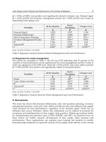
length) placed at x=+m and x=-m respectively as shown in figure B1. Now, due to
single line charge
ρ
L
, the electric field intensity at a distance r is given by
(B1)
where e is permittivity of medium. The potential reckoned from a distance R is
(B2)
The resultant potential at point A (figure B1) due to line charges +
ρ
L
and-
ρ
L
is
(B3)
Copyright © 2004 by Marcel Dekker, Inc.
Appendix B460
Let us now find the nature of equipotential surface having potential of u. From
equation B3 we get
But from figure B1 we have
Solving by componendo and dividendo,
By algebraic manipulations we get
Figure B1 Two line charges placed at x=-m and x=+m
Copyright © 2004 by Marcel Dekker, Inc.
Appendix B 461
(B4)
This is the equation of a circle with radius
and center
Thus, the equipotential surface is a cylinder which intersects the x-y plane in a
circle with radius r and center at (s, 0).
From the above expressions for radius and center we get
(B5)
(B6)
By substituting the value of m in the equation for radius we have
(B7)
Now, from equations B5 and B7 we get
Thus, we get the expression for potential as
(B8)
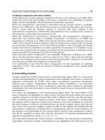
Now, we will consider two parallel cylindrical conductors of radii R
1
and R
2
,
placed such that the distance between their centers is 2s. The electric field
intensity and potential between the two conductors are calculated by considering
the corresponding two equivalent line charges as shown in figure B2.
Copyright © 2004 by Marcel Dekker, Inc.
Appendix B462
Now,
S
1
+S
2
=2s (B9)
Using equation B6 we can write
(B10)
By solving equations B9 and B10 we get
The electric field intensity at point P on the surface of the conductor on the right
side is given by
Now, by putting the value of in the above equation we get
Figure B2 Configuration of two parallel cylindrical conductors
Copyright © 2004 by Marcel Dekker, Inc.
Appendix B 463
By putting the value of s
1
obtained earlier in the above equation we get
(B11)
Now, by using equation B8 for potential, the potential difference between points
P and Q is given as
By putting the values of s
1
and s
2
in the above equation and simplifying,
Putting this value in equation for E
p
(equation B11) we have
(B12)
where
Copyright © 2004 by Marcel Dekker, Inc.
Appendix B464
is called as non-uniformity factor.
Now, if both the electrodes have the same radius, i.e., R
1
=R
2
=R, then
(B13)
where
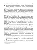
Now, we will consider the other most commonly encountered geometry, i.e.,
cylindrical conductor—plane geometry as shown in figure B3. The ground plane
at point G and the round conductor can be replaced by the configuration of the
conductor and its image as shown in the figure. From equations B12 and B13 the
electric field intensity, in this case, at point P is given as
(B14)
and non-uniformity factor is
(B15)
Figure B3 Cylindrical conductor—plane geometry
Copyright © 2004 by Marcel Dekker, Inc.
Appendix B 465
(B17)
Putting this value in equation for E
G
we get
(B18)
(B19)
The non-uniformity factor f
x
for any point x between the center of the conductor
and ground in the x direction (figure B4) can now be found as below.
The electric field intensity at a point with distance of x from the conductor
center is
(B20)
Now, from equation B8 we have
Now, the electric field intensity at point G is
(B16)
Using equation B8, the potential at the conductor surface is given as
Copyright © 2004 by Marcel Dekker, Inc.
Appendix B466
(B21)
Putting this value in the equation for electric field we get
(B22)
(B23)
The voltage at point x can be calculated using equation B3 as
(B24)
Figure B4 Stress and voltage at any point x from conductor center
Copyright © 2004 by Marcel Dekker, Inc.
Appendix B 467
(B25)
B2 Capacitance Calculations
B2.1 Capacitance between two parallel cylindrical conductors
From figure B2 for the conditions that R
1
=R
2
=R and s
1
=s
2
=s, and by using equation
B8, the capacitance between two parallel cylindrical conductors per unit length is
given by
(B26)
Using equations B5 and B8 and simplifying we get the relation:
(B27)
From the equations B26 and B27, we finally get the capacitance per unit length as
(B28)
B2.2 Capacitance of cylindrical conductor and plane at ground potential
From figure B4 and by using the equation B8, the capacitance per unit length
between a conductor and ground plane is given by
(B29)
Copyright © 2004 by Marcel Dekker, Inc.
Appendix B468
By using equation B27, we get the capacitance per unit length between the
conductor and ground as
(B30)
Copyright © 2004 by Marcel Dekker, Inc.