Báo cáo lâm nghiệp: "Utilization of a dynamometric pendulum to estimate cutting forces involved during routing. Comparison with actual calculated values" pdf
Bạn đang xem bản rút gọn của tài liệu. Xem và tải ngay bản đầy đủ của tài liệu tại đây (1.24 MB, 7 trang )
441
Ann. For. Sci. 62 (2005) 441–447
© INRA, EDP Sciences, 2005
DOI: 10.1051/forest:2005040
Original article
Utilization of a dynamometric pendulum to estimate cutting forces
involved during routing. Comparison with actual calculated values
Florent EYMA
a
*, Pierre-Jean MÉAUSOONE
b
, Pierre LARRICQ
a
, Rémy MARCHAL
c
a
IUT Paul Sabatier, 1 rue Lautréamont, 65000 Tarbes, University of Toulouse, France
b
ENSTIB, 27 rue du Merle Blanc, 88000 Épinal, University of Nancy, France
c
ENSAM Cluny, rue Porte de Paris, 71250 Cluny, France
(Received 5 October 2004; accepted 14 March 2005)
Abstract – Nowadays, to measure cutting forces involved during routing, systems with piezo-electric sensors are generally used. This study
began with the following observation: two species with the same density can induce completely different cutting forces. But two species with
completely different densities can also show closed cutting forces. Current formulations used to calculate cutting forces can not explain such
phenomenon. That is why some new research has been done to establish relationship between cutting forces and mechanical parameters [8]. In
this work, we decided to present a very simple, quick and accurate method to obtain similar results and good cutting forces approximation using
a dynamometric pendulum. With this method, we can take into account the machining parameters, wood characteristics, cutting speed, and
impact resistance into just one test. It is possible to quickly know wood behaviour during machining, particularly when new species or new
conditions are used in industries.
cutting forces prediction / dynamometric pendulum / routing / tropical woods
Résumé – Utilisation d’un pendule dynamométrique pour estimer les efforts de coupe en défonçage, comparaison avec les valeurs
actuellement calculées. De nos jours, pour mesurer les efforts de coupe en défonçage, on utilise généralement des capteurs piézo-électriques.
Cette étude a été lancée suite à certaines observations : deux essences avec la même densité peuvent demander des efforts de coupe
complètement différents. Mais deux essences avec des densités complètement différentes peuvent également demander des efforts de coupe
identiques. Les formulations actuellement utilisées ne permettent pas d’expliquer ces phénomènes. C’est pourquoi des travaux de recherche ont
été réalisés pour établir des relations entre les efforts de coupe et les propriétés mécaniques du bois [8]. Dans ce travail, nous avons décidé de
présenter une méthode simple, rapide et précise pour obtenir de bons résultats et de bonnes approximations des efforts de coupe en utilisant un
pendule dynamométrique. Grâce à cette méthode, il est possible de tenir compte des paramètres de coupe, des caractéristiques du bois, de la
vitesse de coupe et de la résistance aux chocs avec seulement un essai. Il est possible de connaître rapidement le comportement du bois pendant
l’usinage, en particulier quand de nouvelles essences ou de nouvelles conditions de coupe sont utilisées dans les entreprises.
prédiction d’efforts de coupe / pendule dynamométrique / défonçage / bois tropicaux
1. INTRODUCTION
This work concerned the routing process 90–0 [11, 16], i.e.,
peripheral milling parallel to grain (longitudinal rotary cutting),
very often used in secondary wood processing. Nowadays,
companies have to improve their cutting process more and
more (because of higher customer requirements, competition
on a world-wide scale, market opening, etc.), and must use new
wood species and products with optimal parameters: it is then,
impossible to do “as usual” [6]. However, there is a lack of
accuracy in the wood behaviour explanation during machining
and chip formation. Quite often, we can find a gap of more than
80% between the cutting forces measured and the current
methods using material coefficient or cutting energy [8]. One
of the main reasons is the lack of knowledge concerning wood
species influence on the force values: this factor remains very
difficult to take into consideration. It is possible to find coeffi-
cients linked to specific gravity or moisture content measure-
ment, but nothing else to obtain very accurate results [12, 14].
Thus, to improve this situation, several routing trials have been
performed.
The first study was to investigate the influence of various
physical and mechanical characteristics on the wood behaviour
during machining [7, 8]. This method allowed us to obtain a
new formulation introducing a new material coefficient Km.
Several authors have introduced mechanical characteristics to
* Corresponding author:
Article published by EDP Sciences and available at or />442 F. Eyma et al.
solve this problem [2, 3, 17], but these authors were concerned
respectively with the cutting modes 0–90 (relevant to peeling
[2, 17]), and 90–90 (relevant to cross-cutting [3]).
However, in the foregoing study, two factors remain difficult
to deal with: cutting velocity and shocks generated when the
tool cuts the wood. Therefore, another process was tested: the
dynamometric pendulum.
Thus, the aim of this study was:
– to improve comprehension of wood behaviour during
routing (chip formation, surface roughness, …);
– to improve prediction of cutting forces;
– to take into account (more conveniently) tool speed,
shocks and wood influence (fiber direction, specific gravity, …);
– to compare results obtained with pendulum and routing
machine.
2. MATERIALS AND METHODS
In order to obtain homogeneous characteristics for each wood spe-
cies [7], it was decided to work on thirteen tropical woods and one
European wood reference namely beech (Fagus sylvatica). The choice
of 13 tropical woods was done with the “CIRAD Forêt” in Montpellier
(France), among a large set of woods presenting a large range for spe-
cific gravity and mechanical characteristics. The moisture content of
each wood specimen was fixed at 12% in order to obtain results close
to literature values. Specific Gravity (SG = Mo/Vsat, i.e. “anhydrous
mass/saturated volume”) of each species was measured.
2.1. Machining tests
Cutting forces measurements were performed on a CNC router
(Computer Numerically Control) using peripheral down-milling par-
allel to the grain. The sample size was: 22 mm in the tangential direc-
tion “T”, 40 mm in the radial direction “R” and 135 mm in the
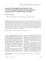
longitudinal direction “L”. A groove was made on the side of speci-
mens in order to process only with the tool’s edge and never with its
top (Fig. 1).
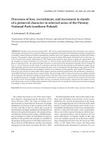
Normal and tangential cutting forces are measured with a piezo-
electric dynamometers attached to the router table as shown Figure 2.
The resultant total cutting force is calculated for analysis. Machining
parameters used are [1]:
– N = 9000 rpm;
– H = 2 mm (depth of cut);
– Ø = 14 mm (tool diameter);
– V
f
= 4 m min
–1
(feed speed);
– b = 9 mm (width of cut);
– Straight edge: 1 tooth with only one tooltip engaged; rake angle:
23°; clearance angle: 15°.
Each value of total cutting forces obtained is a mean of 30 mean
resultant values.
2.2. Dynamometric pendulum adjustment
It was in the first years of XVIII
e
century that Jacques Cassini
showed the pendulum to be a good means to measure energy. It was
only more recently [4, 23], that a dynamometric pendulum was used
to measure wood cutting energy. Chardin worked mainly on sawing
of European and tropical woods. Between 1962 and 1966, [20, 21, 25]
and others, studied on wood cutting characteristics using a dynamo-
metric pendulum.
However, for a long time, with the development of electronic
means of measuring and recording cutting forces, the pendulum
approach has been neglected. Thus, at the beginning of this work, it
was decided to use one of Chardin’s pendulums located currently at
Ensam Cluny, France. Obviously, it was necessary to improve this
pendulum. A device to get samples into position was added, a modi-
fication of tools holders and a chuck arrangement were made. A piezo-
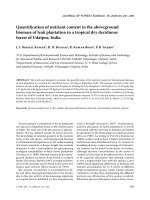
electric dynamometers was added, etc. Results are presented on
Figures 3 and 4.
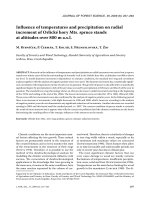
The principle of the measurement is very simple: a tool with only
one tooth (width of 8 mm) is fixed at the tip of a 1.2 m and 36 Kg arm
(Fig. 5). This arm is dropped always from the same height (z
0
). The
first time, the measure is done idle in order to estimate loss of energy
due to the friction (Eq. (1)).
P = m . g . (z
0
– z
1
)(1)
where P = lost of energy linked to the friction m = arm weight.
For each wood species, ten measurements of cutting energy have
been done reading the maximum angle obtained by the arm just after
cutting (ω ), (Eq. (2)):
E
cutting
= m . g . (z
1
– z
2
) = m . g . ( Cos θ – Cos ω )(2)
Figure 1. Wood specimen used for routing.
Figure 2. Specimen on router’s table with its cutting forces measuring
device.
Use of pendulum to estimate cutting forces in routing 443
where m = arm weight; E
cutting
= cutting energy measured; θ = angle
obtained idle (without sample); ω = angle obtained after cutting.
The cutting energy is divided by sample length (l
cutting
) to obtain
the mean total cutting forces (F
T
), (Eq. (3)):
.
(3)
Samples size is: 5 mm (T), 40 mm (R) and 140 mm (L). Like for
routing tests, a cutting speed of almost 7 m s
–1
is used (like for routing
tests). Moreover, similar cutting conditions were used (rake angle,
clearance angle, cutting plane, etc.). The depth of cut has been
decreased to 1mm in order to obtain appropriate chip formation. Each
value of cutting forces reported, is a mean of ten measurements
obtained on each species.
This pendulum was adapted for easy adaptability: possibility of
working with or without piezo-electric dynamometers, use of several
workpiece fastening possible, etc. Thus, the aim of the present study
was:
– Firstly, to compare pendulum results with values obtained using
routers and piezo-electric sensors;
– Secondly, to find a cheaper and more convenient method not
requiring computerized force recording, for rapid assessment of
wood behaviour and cutting forces involved during machining.
3. RESULTS AND DISCUSSIONS
3.1. Measurements on the router [9]
At the beginning of this study, the aim was to take into
account the influence of wood material in the estimation of cut-
ting forces involved during routing. It was decided to work on
wood mechanical properties involved during routing [10, 13,
22, 24], namely: Monnin hardness, fracture toughness in mode I,
shearing and compression parallel to the grain. Cutting forces
have been measured on routers (30 values for each species).
Tests results were combined, (different mathematical models
were tested) and several models were obtained. The highest
significant correlation was obtained for the following equation
using three properties : P
f,I
(elastic parameter in fracture tou-
ghness), Ec (modulus of elasticity in compression), and SG
(specific gravity) (in order to know if each factor was signifi-
cantly separate in the correlation, a student test “t” was carried
out). F
c
is total cutting forces during routing.
Figure 3. Dynamometric pendulum.
Figure 4. Details of pendulum arm and of device to get sample into
position.
F
T
E
cutting
l
cutting
=
Figure 5. Use principle of dynamometric pendulum, where Z
0
= arm
starting height. Z
1
= arm height after test without sample; Z
2
= arm
height after test with sample.
444 F. Eyma et al.
F
c
= (0.00139 . P
f,I
) + (0.0031 . )
.
(4)
This model allowed an improvement of 30% of the coeffi-
cient of determination (R
2
= 0.80) in the relation between pre-
dicted cutting forces and routing measurements, and a
reduction of 60% of errors sum of squares. It takes into account
wood species influence with the introduction of a new material
coefficient “K
m
”.
K
m
= (5.73 × 10
–5
× ) + (2.57 × 10
–5
× P
f,I
). (5)
This coefficient “Km” allowed the use of the following
equation described in Eyma’s thesis to calculate cutting [8]:
F
c
= F1 × b × Km × Kh(6)
where F1 correspond to the influence of cutting process and
chip thickness; b is the width of cut and Kh is moisture content
coefficient [14].
Moreover, it also permits to estimate more accurately which
mechanical properties are mainly involved during routing; and
even if generally, mechanical stresses depend on chip forma-
tion [11, 15, 16, 19], it appears clearly that, in routing, notions
of crack propagations (with fracture toughness parameter), and
cellular-wall mechanical strength (with the specific compres-
sion modulus) are especially important to understand cutting
forces involved.
However, at that state of the study, the question was: is it
possible to obtain the same precision more easily, without
expensive material (piezo-electric sensors, router, etc.), and
maybe with more information (on impact and speed influence)?
3.2. Measurements using the pendulum
8 Before beginning tests, the accuracy of measurements
was estimated. Results showed a very high repetitivity with a
variation coefficient of 0.1%. These gaps are really non signi-
ficative and can be explained by manual sample positioning and
wood heterogeneity. Moreover, these results show that angular
measurements made on pendulum are reliable and accurate.
8 Then, the influence of cutting speed (varying with the
pendulum arm height) was tested (Eq. (7)). Ten speeds, from
0.1 to 8 meter per second were used with two species : Beech
(Fagus sylvatica) and Ipé (Tabebuia sp.).
V
c
= (7)
where V
c
= cutting speed (m s
–1
);
α
= start angle of arm pen-
dulum; L = arm length (m); g = acceleration due to gravity.
Results show that cutting speed does not have any influence
on cutting forces observed. The same study was done on router
and gave the same results (Fig. 6).
It confirms some other results [11, 14, 16] but, is something
contested by researchers of high-speed machining [5] where an
increase of speed leads to a decrease of cutting forces involved.
Then, in this study, cutting speed was chosen arbitrarily to be
7.6 m s
–1
.
8 Influence of chip formation: In early tests, a depth of cut
of 2 mm was used. However, for some wood species it occurred
that chip tearing was excessive, and the analyze of cutting forces
measured with piezo-electric sensors was impossible because
of signal perturbations. Moreover, cutting forces measure-
ments were very close to cutting forces measured with a 1mm
depth of cut. This phenomenon appeared for most wood species
except for very hard wood like Ipé (Tabebuia sp.) or Boco
(Bocoa prouacensis Aubl.). In these cases, with a depth of cut
of 2 mm, the cutting forces were twice as high, as expected.
These observations can be explained by something very
important in machining: the “Good Cutting Area” [4]. It is not
always possible to speak about wood cutting: in some condi-
tions, beyond some depth of cut, beyond some cutting speed,
there is no more chip formation, but wood tearing with succes-
sive cracking during chocks between wood and tool. Thus, in
experimentation, it is always necessary to find optimal cutting
conditions to have chip formation and to avoid wrong analysis.
In industrial machining, this choice of optimal conditions can be
done using the “Coupled Tool-Material” method for example [18].
The difference between wood species can be explained by
chip formation mechanism. In the case of very hard woods like
Ipé or Boco, chips obtained are fragmented (with a frequency
of 300 Hz corresponding to a wood cracking each 2 cm), whe-
reas for the other wood species, chip is rolled, and regular split-
ting can be observed with a frequency of 600 Hz.
Concerning measurements made with the piezo-electric
dynamometer on the pendulum, it was observed on each cutting
forces curve, residual perturbations (frequency of 150 Hz) after
cutting whatever the wood species and the depth of cut. Moreo-
ver, it appeared that cracking frequency on chip formation is
always proportional to this same frequency of 150 Hz (Fig. 7).
Thus, a very interesting possibility is to obtain cracking frequency
(and then, surface roughness information) just observing the
cutting forces signal [8]. However, these perturbations are not
Ec
SG
Ec
SG
2 · g · L · 1
α
cos+()
Figure 6. Cutting speed influence on cutting forces measured.
Figure 7. Cutting forces signal.
Use of pendulum to estimate cutting forces in routing 445
a problem for us; because the aim of piezo-electric sensors used,
is only to confirm results simply obtained with arm rising.
8 Influence of arm weight: no tests were done on this factor
because of results found in literature [21]. The arm weight does
not have any influence on chip formation and cutting forces
involved (the gravity center is almost at the arm tip).
3.3. The pendulum: results and comparisons
8 The first results obtained were concerned with the relation
between cutting forces measured on router (F
r
) and cutting for-
ces measured on pendulum (F
p
). A linear correlation was obtai-
ned (Fig. 8) between these two parameters, with a good
coefficient of determination: R
2
= 0.78.
Thus, it is possible, more easily than with actual tests and
formulations [9], to know from a simple test on pendulum, the
power demand of wood during machining (taking into account
wood material influence, impacts, cutting speed, etc.).
8 In order to compare values obtained, each calculated cut-
ting forces (on router and on pendulum) was divided by the
removed chip volume calculated with mean chip thickness and
dimensions of each specimen described previously. All results
are presented in Table I.
Different parameters used are: SG = Specific Gravity; F
p
is
the mean cutting forces measured on pendulum; F
r
is the mean
cutting forces measured on routers; F
[6]
is the mean cutting for-
ces obtained with new formulation (Eq. (6)); V
r
is the removed
chip volume during routing; V
pend
is the removed chip volume
with pendulum. There are clearly some differences between
measured values, with discrepancies of more than 50% between
router (reality) and pendulum values for some wood species.
Nevertheless, it is something very easily explainable, mainly
by two reasons:
– Firstly, in the case of pendulum (Fig. 4), there are some
frictions on tooth lateral sides, whereas it is not the case in
routing where cutting process is done only with the side of
tools edge and never with the top;
– Secondly, chip formation is different: with pendulum
there is formation of a continuous chip (constant chip thick-
ness, close to Franz chip type I), whereas it is not the case in
rotating cut like routing (close to Franz chip type II).
However, even if values can not be directly measured, pen-
dulum testing provides a sufficiently and accurate estimate of
cutting forces involved during routing. The regression equation
from Figure 8 is:
F
r
= 0,42 . F
p
+ 5.48 (8)
R
2
= 0.78
where Fp is the cutting forces involved during routing.
In comparison with models used to estimate cutting forces
in routing [8], there is an improvement of more than 25% in
Table I. Comparison of cutting forces obtained on router (F
r
) and pendulum (F
p
).
Wood species Cutting forces Comparison router / pendulum
Name Scientific name SG F
r
(N) F
[6]
(N) F
p
(N) F
r
/ V
r
(N mm
–3
)F
p
/ V
pend
(N mm
–3
) Difference (%)
Fromager Ceiba pentandra Gaertn. 0.204 21.1 21.5 36.7 2.7 4.1 35
Ayous Triplochiton scleroxylon 0.315 30.5 25.7 47.3 3.8 5.3 27
Virola Virola spp. 0.418 36.7 34.4 57.1 4.6 6.3 27
Niangon Tarrietia densiflora 0.47 46.6 43.5 85.6 5.9 9.5 38
Grignon franc Ocotea rubra 0.485 28.9 31.8 51.9 3.6 5.8 37
Dodomissinga Parkia nitida 0.499 41.7 38.7 82.0 5.2 9.1 43
Frake Tarminalia superba 0.554 34.6 39.6 73.1 4.4 8.1 46
Beech Fagus sylvatica 0.573 33.2 34.5 78.7 4.2 8.7 52
Bagasse Bagassa guianensis 0.689 36.8 41.4 88.2 4.6 9.8 53
Eucalyptus Eucalyptus globulus 0.705 46.3 39.7 116.2 5.8 12.9 55
Moabi Baillonella toxisperma 0.714 35.1 37.1 75.9 4.4 8.4 48
Wacapou Vouacapoua americana 0.755 34.1 40.4 68.2 4.3 7.6 43
Ipé Tabebuia sp. 0.851 44.9 44.3 106.6 5.7 11.8 52
Boco Bocoa prouacensis 1.109 55.2 53.0 108.9 6.9 12.1 43
Figure 8. Relation between cutting forces obtained on router and on
pendulum.
446 F. Eyma et al.
precision, and better representation of wood material influen-
ces (wood characteristics, anatomy, …).
Then, in comparison with the first method obtained with
mechanical properties (Eq. (6)), the dynamometric pendulum
is a valuable means, very simple and cheap (not requiring
expensive electronic instrumentations), to predict wood beha-
viour and cutting forces involved, taking into account the
influence of:
– Wood species and wood properties: very important factor
as described in the previous work;
– Cutting conditions: velocity, chip thickness, tool’s
angles, etc.;
– Impacts: very important in machining and responsible for
cracking behind the cutting edge.
It is a very good representation of reality, and a good way
to obtain indications and results on the influence of many para-
meters in machining (it could be adapted for other kinds of
machining such as sawing or peeling).
A verification of these results was performed on three other
species: Movinghi (Distemonanthus benthamianus), Ash
(Fraxinus excelsior) and Spruce (Picea sp.). Similar mechani-
cal properties and machining tests were carried out, and
allowed to validate these correlations [8]. This provided vali-
dation for Movinghi and Ash; but application to Spruce was less
successful. Nowadays, it is something already explained with
wood anatomy in a previous work [7].
A comparison between results obtained with pendulum
(Fig. 8), and results obtained with one of current formulations
(using specific gravity to describe wood material influence,
Fig. 9), can be done with an improvement of 20% of the deter-
mination coefficient (respectively from 0.54 to 0.78).
4. CONCLUSION
Following on investigation of wood material influence and
mechanical solicitations involved during routing, the aim was
to know if an other method, more simple, cheaper and easily
adaptable could give the same (or better) results: the dynamo-
metric pendulum.
Results obtained were favourable. The pendulum proved to
be a good and practical means to assess cutting properties of
new wood species or when new conditions are to be used.
Moreover, it allowed taking into account a lot of parameters dif-
ficult to study before: impacts, cutting speed, etc. It is very
important for wood laboratories and wood industries to have
the possibility to, simply and quickly, characterize new wood
species or new wood composites in order to find optimal cutting
conditions. This is more and more often required because of
higher customer requirements and competition. Also, there is
a need to use costly high-production machines such as routers
more efficiently.
This method opens new perspectives for further develop-
ments impossible to contemplate simply before. In the future,
a smaller pendulum, more convenient should be studied; and
standards could be developed like for hardness or compression,
to translate wood cutting strength more accurately.
Acknowledgements: Special thanks to W.M. McKenzie for his
advice, and his help in the achievement of this work. We would also
like to thank the Cirad forest for funding experimental tropical wood,
and all the staff of ENSAM - Cluny, for their help in the achievement
of pendulum tests.
REFERENCES
[1] Aguilera A., Optimisation des conditions de coupe pour l’usinage
du bois, Thèse de l’Univ. Henri Poincaré de Nancy I, 2000.
[2] Bardet S., Beauchêne J., Thibaut B., Influence of basic density and
temperature on mechanical properties perpendicular to grain of ten
wood tropical species, Ann. For. Sci. 60 (2003) 49–59.
[3] Beauchêne J., Évolution du comportement mécanique du bois vert
avec la température – application à l’étude du déroulage et du tran-
chage de quelques bois Guyanais, Thèse présentée à l’ENGREF,
1996.
[4] Chardin A., Utilisation du pendule dynamométrique dans les recher-
ches sur le sciage des bois, Rev. Bois For. Trop. 58 (1958) 49–61.
[5] Costes J.F., Approche de l’usinage à grande vitesse du bois : appli-
cation au défonçage, Thèse de l’université de Toulouse III, 2001,
141 p.
[6] CTBA., État de l’art et évolutions des performances des machines
d’usinage du bois travaillant par enlèvement de copeau, 1991.
[7] Eyma F., Influence des caractéristiques physiques et mécaniques du
bois sur l’usinage, Rapport de DEA Sciences du bois, Univ. Nancy I,
1999.
[8] Eyma F., Caractérisation des efforts de coupe de différentes essen-
ces de bois à l’aide de leurs paramètres mécaniques, thèse de
l’Univ. Henri Poincaré Nancy I, 2002.
[9] Eyma F., Méausoone P.J., Martin P., Study of the properties of thir-
teen tropical wood species to improve the prediction of cutting for-
ces in mode B, Ann. For. Sci. 61 (2004) 55–64.
[10] Fischer R., Wood cutting simulation – A program to experiment
without a machine, in: Proc. of the 14th Int. Wood Mach. Sem.,
1999, pp. 553–562.
[11] Franz N.C., An analysis of the wood-cutting process, Univ. of
Michigan Press, Ann. Arbor. Mich., 1958.
[12] Gonçalves M.T.T., Rodrigues R., Takahashi J.S.I., An experimen-
tal analysis of the influences of machining conditions on the parallel
cutting force in orthogonal cutting for ten Brazilian wood species, in:
Proc. of the 13th Int. Wood Mach. Sem., 1997, pp. 481–487.
[13] Huang Y S., Hayashi D., Basic analysis of mechanism in wood-
cutting. Stress analysis in orthogonal cutting parallel to grain, Mok.
Gak. l19 (1973) 7–12.
[14] Kivimaa E., Cutting force in wood working, Helsinki, 1950.
Figure 9. Relation between cutting forces obtained on router and with
one of current formulations [8].
Use of pendulum to estimate cutting forces in routing 447
[15] Koch P., Wood machining process, Cambridge, Ronald press,
1964.
[16] McKenzie W.M., Fundamental analysis of the wood cutting proc-
ess, thesis of the dept. of wood tech., school of natural resources,
Univ. Michigan, Ann. Arbor., 1961.
[17] McKenzie W.M., Cowling R.L. A factorial experiment in trans-
verse-plane (90/90) cutting of wood – Part I; Cutting force and edge
wear, Wood Sci. 3 (1971) 204–213.
[18] Méausoone P.J., Aguilera A., Martin P., Choice of optimal condi-
tions in wood machining using the “Coupled Tool-Material”
method, in: Proc. of the 15th Int. Wood Mach. Sem., 2001,
pp. 37–47.
[19] Merchant M.E., Mechanics of the metal cutting process (I) – ortho-
gonal cutting and a type II chip, J. Appl. Phys. 16 (1945) 267–275.
[20] Noguchi M., Sugihara H., Matsuyoshi R., Studies on Wood Cutting
with a Pendulum Dynamometer (V) – Effect of moisture content –
Wood Res. 34, 1965.
[21] Noguchi M., Sugihara H., Okushima S., Nomura K., Studies on
Wood Cutting with a Pendulum Dynamometer (VI) – Relation
among Cutting Energy, Cutting Force and Type of Chip Formation,
Wood Res. 39, 1966.
[22] Orlenko L., Orlenko E., Making the mathematical model of the
wood cutting process, in: Proc. of the 14th Int. Wood Mach. Sem.,
1999, pp. 719–723.
[23] Reineke, Sawteeth in action, in Proc. of FPRS, Madison, 1951.
[24] Stewart H.A., Chip formation when orthogonally cutting wood
against the grain, Wood Sci. 3 (1971) 193–203.
[25] Sugihara H., Noguchi M., Studies on Wood Cutting with a Pendu-
lum Dynamometer (I), Wood Res. 28 (1962) 31.
To access this journal online:
www.edpsciences.org