Báo cáo toán học: "Hyperbolization of Euclidean Ornaments" pptx
Bạn đang xem bản rút gọn của tài liệu. Xem và tải ngay bản đầy đủ của tài liệu tại đây (11.76 MB, 29 trang )
Hyperbolization of Euclidean Ornaments
Martin von Gagern & J¨urgen Richter-Gebert
Lehrstuhl f¨ur Geometrie und Visualisierung
Zentrum Mathematik, Technische Universit¨at M¨unchen, Germany
,
Submitted: Oct 30, 2008; Accepted: May 5, 2009; Published: May 22, 2009
Mathematics Subject Class ification: Primary 51M09, 52C26; Seconda ry 51F15, 53A30, 53A35
Abstract
In this article we outline a method that automatically transforms an Euclidean
ornament into a hyperbolic one. Th e necessary steps are pattern recognition, sym-
metry detection, extraction of a Euclidean fundamental region, conformal deforma-
tion to a hyperbolic fundamental region and tessellation of the hyperbolic plane
with this patch. Each of these steps has its own mathematical subtleties that are
discussed in this article. In particular, it is discussed which hyperbolic symmetry
groups are suitable generalizations of Euclidean wallpaper groups. Furthermore it is
shown how one can take ad vantage of methods from discrete differential geometry in
order to perform the conformal deformation of the fu ndamental region. Finally it is
demonstrated how a reverse pixel lookup strategy can be used to obtain hyperbolic
images with optimal resolution.
1 Introdu ction
Ornaments and regular tiling patterns have a long tradition in human culture. Their ori-
gins reach back to ancient cultures like China, Egypt, Greece and the Islam. Each of these
cultures has its own specific way to create symmetric decora tive patterns. Mathemati-
cally the underlying structures are well understood. Taking only the pattern into account
(and neglecting possible color symmetries) there are just 24 sporadic groups and 2 infi-
nite classes of groups governing the symmetry structure of plane images. The two infinite
classes belong to rosette patterns with an n-fold rotat io nal symmetry (having reflections
or not). Furthermore there are 7 frieze groups describing patterns that have translational
symmetry in a single direction. And last but not least there are the most interesting ones,
the 17 wallpaper groups for patterns that admit translational symmetries in at least two
independent directions. The frieze and wallpaper groups are infinite symmetry groups.
Structurally we have to tell apart at least three different layers when speaking about
symmetric patterns – two of them belong to mathematics and one belongs to art. Starting
the electronic journal of combinatorics 16(2) (2009), #R12 1
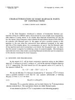
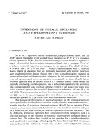
Figure 1: A planar Euclidean ornament with its underlying symmetry structure
with a concrete symmetric pattern P we are interested in its symmetry structure. For
this we embed the pattern in R
2
and study all Euclidean symmetries of this pattern. One
formal way to do this is to define a mapping P : R
2
→ C where C is a suitably rich set that
resembles a color space. For instance we could take C = [0, 1]
3
to be the red/green/blue
color values of each point in the plane. We are looking for all Euclidean transformations
that leave the pa tt ern invariant. Let euc be the set of all possible Euclidean isometries.
The symmetry group of the pattern P is sym(P) := {g ∈ euc | P ◦ g = P}, where
P ◦ g is a shorthand for first applying the Euclidean symmetry and than looking for the
color a t the transformed position. The symmetry group is the part of the automorphism
group of P that belongs to euc. In other words we arrive at the same color for every
location in the or bit orb(x) := {g(x) | g ∈ sym(P)}. This agrees with Hermann Weyl’s
famous definition of symmetry: “an object is symmetric if it remains the same under some
transformations”. Under the assumption that P does not admit continuous symmetries,
each planar pattern P has a symmetry group falling into one of the (conjugacy) classes
mentioned above. (The extreme case of a pattern without any repetitions is covered by
the rosette group that has only a 1-fold rotation.) The conjugacy class of the symmetry
group is in a sense the highest level o f abstraction.
On a less abstract level each pattern is asso ciated to a concrete symmetry group.
Within the same conjugacy class these concrete groups may still differ by a variety of
parameters, like scaling, rotations, etc. Factoring out Euclidean transformations, some of
these classes turn out to have just one unique representation. This happens for all rosette
and frieze groups. For wallpaper gr oups this effect typically arises when a rotational
symmetry of order at least three is present. We call such groups highly symmetric. The
remaining wallpaper groups still have one or two degrees of freedom in their concrete geo-
metric representation. They correspond to an anisotropic stretching in a certain direction
or an a ng le between the generating directions. The specific geometric representation of a
group is the second mathematical level we have to consider.
Finally, there is the artistic level, which is responsible for the concrete motive that is
repeated in the ornament (see Figure 1). Here one has all artistic freedom from complete
arbitrariness and noise to sophisticated ornamental designs as they occur for instance in
the electronic journal of combinatorics 16(2) (2009), #R12 2
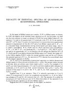
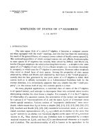
Figure 2: A tessellation of the hyperbolic plane and M.C. Escher’s Circle Limit III,
woodcut 1959.
the Islamic ornamental art. The visual appearance of an ornament may vary drastically
with its artistic input. There is a clear concept that helps to draw a border between the
artistic and the mathematical level of an ornamental pattern: the fundamental domain.
This is a (connected) region in the original pattern that contains exactly one point from
each orbit of the pattern. Thus within (the interior of) a fundamental domain there is no
repetition at all and one has full artistic freedom. If each point of one fundamental domain
is colored then all the rest of the ornament is determined by the underlying symmetry
group. Multiple copies of the fundamental domain generate the pattern. One of the aims
of this paper is to provide a metho d that allows one to take the high-quality artistic
input of classical ornaments and turn them into patterns with new and amazing kinds
of symmetry. In other words we are interested in the generation of artistically valuable
fundamental domains for interesting symmetry groups.
As mentioned above the structure of Euclidean ornaments is well understood and in a
sense a classical topic of geometry (see [9, 10, 18, 19]). It very seldom happens that there
are specific moments that represent a pivot in the interaction of mathematics and art.
But in the case of ornaments there seems to have been at least one such. At a conference
in 1954 the famous Dutch artist and lithograph M. C. Escher and H. S. M. Coxeter first
met. They exchanged many ideas on the interrelations of mathematics, geometry and art.
The conference resulted in a friendship and an exchange of letters. One of these letters
of Coxeter to Escher contained a rendering of a hyperbolic tessellation in the Poincar´e
disk as it could also be found in Felix Klein’s and Poincar´e’s work (see Figure 2 left).
Escher claimed that he was shocked by this picture since it resolved a problem he had
been struggling with for several years: How to fit infini tely many similar objects in to the
finite limits of a circle. Inspired by this drawing Escher produced a sequence of pictures –
his famous Circle Limit I – IV (see Figure 2 right). And in reaction to this Coxeter wrote
a beautiful article describing the subtle mathematics of these pictures [5, 6].
The hyperbolic plane allows several (hyperbolic) rotat io n centers of arbitrary degree.
the electronic journal of combinatorics 16(2) (2009), #R12 3
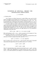
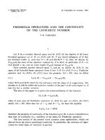
Figure 3: The ultimate aim of this article: Transf orming a scanned Euclidean input
image to a perfect hyperbolic ornament
Hence in contrast to the Euclidean plane in the hyperbolic plane there are infinitely many
structurally different symmetry groups. Nevertheless the amount of available artistically
interesting images of hyperbolic ornaments is very limited, and still the few examples
created by Escher are the outstanding period of this art. The reasons for this are ob-
vious. A person creating hyperbolic ornaments has to cope with several problems and
to be equipped with several skills. He/she has to be artistically gifted and has to know
the mathematical backgrounds of hyperbolic tessellations including the highly non-trivial
geometric construction principles. Furthermore he/she has to find a way to produce in-
finitely many ever so tiny copies of the object that has to be repeated (the fundamental
region). There are several a t t empts to create such images by computer. Some of them [3]
try to automatically create fundamental regions that match a given concrete shape. Oth-
ers try to manually transform Euclidean patterns to create similar hyperbolic patterns
[8]. There are also attempts [16] to take original picture parts of Escher images, deform
them manually to fit approximately to a hyperbolic fundamental region and use this as a
basis for a tessellation. These latter come in a sense closest to the ones generated by the
methods describ ed in this article. However, they suffer from visual seams which appear
at the boundaries of the patches.
Also there are several programs that can be used to create individual designs for a
specific symmetry group by mouse interactions (drawing lines, placing objects). Most of
these programs also suffer from the problem of creating infinitely many objects in finite
time and are of doubtful artistic quality.
In this article we want to take a different approach. We want to outline a method
that allows o ne to take a classical ornamental pattern, feed it into a computer and create
corresponding seamless hyperbolic patterns. Thus we want to keep the artistic content (of
the old masters), while changing the symmetry structure of the overall picture. Figure 3
exemplifies input and a possible output of the program. The present article outlines the
the electronic journal of combinatorics 16(2) (2009), #R12 4
different steps of this production process.
• Pattern recognition: We use autocorrelation methods based on discrete Fourier
transforms to detect symmetries of the original picture and to identify the structure
of its symmetry g r oup.
• Finding corresponding hyperbolic groups: An analysis of the symmetry group
is used to determine which hyperbolic groups match the original symmetry group.
• Conformal deformation: We create a conformal deformation of the original fun-
damental region to the corresponding hyperbolic region. The theory of this step
is governed by Riemann’s famous mapping theorem. However, practically feasible
implementations of this step need sophisticated methods from the relatively new
field of discrete differential geometry [2]. In particular, we use discrete conformal
mappings as introduced in [20].
• Creating the image: Finally, the unit Poincar´e disk has to be covered with in-
finitely many copies of the fundamental region according to the chosen symmetry
group. In order to obtain a perfect raster image we use a pixel oriented algorithm
that calculates for each pixel its corresponding color.
The rest of the a r ticle is organized as follows. After outlining some elementary concepts
and definitions we focus in Section 3 on the task of transforming a Euclidean ornament
into a hyperbolic one. Section 4 is dedicated to the pre- and post-processing – this means
the pattern recognition and the task of filling the entire Poincar´e disc with the pattern.
In Section 5 we present a collection of interesting examples. F inally, Section 6 points to
further proj ects and problems in t his context that are not covered by this article. The
article is meant as an overview of the subjects and our methods a nd omits several technical
details in or der to emphasize the overall picture.
2 Concepts
This section covers several fundamental concepts needed for the rest of the article. We
assume that the reader is familiar with elementary concepts of wallpaper groups and with
hyperbolic geometry.
2.1 The Crystallographic Groups
The input pictures that we will use will all be Euclidean wallpaper ornaments. These
pictures admit translational symmetries in at least two independent directions. Besides
translations also rotations, reflections and glide reflections are allowed. The classification
of these groups dates back to the late 19th century and is due to Fedorov, Sch¨onflies and
Barlow [1, 9, 10, 18, 19 ]. There are exactly 17 conjugacy types of such gro ups. Different
nomenclatures have been proposed during the centuries. We here will stick to the IUC
the electronic journal of combinatorics 16(2) (2009), #R12 5
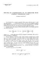
p1 p4
p2 p4m
pm p4g
pg p3
cm p3m1
pmm p31m
pmg p6
pgg p6m
cmm
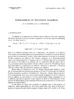
Table 1: Ornaments and their wallpaper groups
the electronic journal of combinatorics 16(2) (2009), #R12 6
notation, which is the notation for the symmetry groups ado pted by the International
Union of Crystallography in 1952 [14]. A list of all 17 groups is given in Table 1 (the
table first appeared in [11] and is based on the beautiful collection of classical ornaments
published by Owen Jo nes in 1910 [15]). The table gives one example for each of the
groups and overlays a diagram indicating the symmetry structure of the group. Double
lines represent reflections. Polygons represent rotation centers and dashed lines represent
glide reflections. In the nomenclature a letter m indicates the presence of a reflection,
a g indicates a glide refection and a number n > 1 indicates the presence of an n-fold
rotation.
A concept that will turn out important for our purposes will be the fundamental region
(or fundamental domain) F of a wallpaper group G ⊂ euc. The orbit under G of a point
p is the equivalence class {g ◦ p | g ∈ G}.
Definition 1 A fundamental region F of a wallpaper group G ⊂ euc is a connected and
closed region in R
2
that contains at least on e point from every orbit of the group, such
that the images of F under G cover R
2
and such that two such images have no interior
points in common.
Fundamental regions with fractal boundary are objects of current research. However,
we will neglect this case here. For Euclidean wallpaper groups we will only consider poly-
gonal fundamental regions. Later on in the hyperbolic case we will also admit hyperbolic
polygons (i.e. bounded by Euclidean circular arcs in the Poincar´e disk). While all interior
points of F belong to different orbits, it may happen that several b oundary points of F
belong to the same orbit. For a particular colored symmetric pattern P : R
2
→ C the
artistic content is given by the behavior within a fundamental region. The whole pat-
tern is generated by gluing infinitely many copies (some of them perhaps reflected) of the
fundamental region along their boundaries.
Some of the wallpaper g roups turn out to be two-dimensional reflection groups or
are closely r elated to them. The groups p4m, p3m1 and p6m correspond to the three
Euclidean triangular kaleidoscopic fundamental regions with corner angles (90
◦
, 45
◦
, 45
◦
),
(60
◦
, 60
◦
, 60
◦
) and (90
◦
, 60
◦
, 30
◦
), respectively. The groups p4, p3 and p6 are the corre-
sponding reflection free subgroups. These groups are index two subgroups of the corre-
sponding reflection groups. The groups p31m and p4g can also be considered as index
two subgroups of p6m and p4m, respectively. All these groups have only one possible geo-
metric conjugacy class, since they are (up to a global Euclidean transformation) uniquely
determined by the shape of the underlying triangles. There is one more reflection group,
namely pmm. It corresponds to a rectangular kaleidoscope with four 90
◦
corners. It has
a one parameter family of conjugacy classes parametrized by the ratio of two adjacent
edges.
Here we will discuss “hyperbolizations” of wallpaper groups that contain at least one
proper center of rotation. In addition to the above mentioned groups these are p2, pmg,
cmm, pgg. The groups pmg, cmm and pgg have a one parameter family of g eometric
conjugacy classes. The group p2 has two geometric parameters (its fundamental region
can be an arbitrary triangle).
the electronic journal of combinatorics 16(2) (2009), #R12 7
2.2 Hyperbolic Ornaments and Hyperbolization
Analogously to Euclidean wallpaper groups we will a lso consider hyperbolic ones. By
default we will use the Poincar´e model of the hyperbolic plane. The hyperbolic plane
is the interior of the unit disk H := {z ∈ C | |z| < 1} in C equipped with a certain
metric (see for instance [12] for further details). In this model hyperbolic lines correspond
to Euclidean circular arcs that intersect the boundary of the Poincar´e disc orthogonally.
The model is conformal in the sense that hyperbolic angles between hyperbolic lines
correspond to the intersection angle of the corresponding circles. Orientation preserving
hyperbolic isometries are given by M¨obius transformations µ : H → H that leave the unit
circle as a whole invariant. Orientation reversing hyperbolic isometries are obtained by
combining a M¨obius transformation with complex conjugation. By hyp we denote the
set of all these isometries. Now a hyperbo lic ornament is a color pattern P : H → C
that admits a discrete symmetry group sym(P) := {g ∈ hyp | P ◦ g = P}. In contrast
to the Euclidean case in the hyperbolic plane there are infinitely many different discrete
symmetry groups having more than o ne center of rotation.
The simplest of these groups are the triangular reflection groups generated by trian-
gular kaleidoscopes with angles
π
k
,
π
m
,
π
n
, where k, m, n ∈ N and
1
k
+
1
m
+
1
n
< 1. Already in
this case there are infinitely many different such groups governed by the different choices
of k, m, n. In our approach these groups will play a special role, since they are especially
easy to deal with.
Before coming back to these groups we will define what we mean by a hyperboliza tion
of a Euclidean ornament. As mentioned in the introduction we want to maintain as much
as possible of the art istic input. In particular shapes and angles should only be minimally
distorted by the deformation of the fundamental cell. For this reason we require the
deformation to be a confor mal mapping except for the ro t ation centers. We identify
the Euclidean plane with the complex numbers C. We will define hyperbolization by an
analytic continuation process of a function f that is consistent with the symmetry of the
pattern P.
Definition 2 Given a Euclidean pattern P that belongs to a specific wallpaper group
G ⊂ euc. Furthermore, let P
′
: H → C be a hyperbolic ornament with some underlying
discrete hyperbolic group G
′
⊂ hyp. Let U ⊂ C be a small region that does not contain
a rotation center of G. We say that P
′
is a hyperbolization of P if there is a conforma l
map f : U → H such that
• P(z) = P
′
(f(z)) f or all z ∈ U and
• For any analytic path ψ : [0, 1] → C with ψ(0) ∈ U that avoids all rotation centers
of G the analytic continuation
f(z) o f f satisfies P(ψ(1)) = P
′
(
f(ψ(1))).
The analytic continuation of f connects (conformally) the color patterns P and P
′
. If
we trace any path in C that avoids rotation centers the colors of the two patterns will
coincide for z and
f(z), respectively. It should be mentioned that at the rotation centers
considerable monodromy could occur. Imagine that we have a fourfold rotation center r
the electronic journal of combinatorics 16(2) (2009), #R12 8
in P that gets mapped to a fivefold rotat io n center r
′
in P
′
. If we start with some point
z sufficiently close to r and with a corresponding image p oint
f(z) then each full cycle
around r causes the image point to perform a
4
5
turn around r
′
. Only after five full cycles
the image z and
f(z) are both back to their original position.
2.3 Orbifolds
One of the most successful concepts in the study of symmetric patterns is the underlying
orbifold. In our context it will sometimes be useful to perform considerations on the level
of orbifolds rather than on the level of fundamental regions. Similar to wallpaper groups
the orbifold can also be considered on a geometric and on a combinatorial (topological)
level. The orbifold is an abstract two-dimensional manifold, that contains exactly one
point from each orbit of a wallpaper group. For a detailed introduction to the theory of
orbifolds we refer to the beautiful book [4]. Here we only introduce the concepts necessary
in our context. In the Euclidean plane we consider a polygonal fundamental region F of a
wallpaper group G. The orbifold now can be considered as a copy of a single fundamental
cell where boundary points that are identified via G are glued together. The edges of F
that belong t o reflections become the boundary of the orbifold, while centers of rotation
become corner points on the boundary or cone points in the interior of the orbifold,
depending on whether they lie on an axis of reflection or not. Figure 4 illustrates the
concept. It shows t he famous Angel and Devil ornament of M. C. Escher. The symmetry
group o f this picture is p4g. The drawing in the middle highlights a fundamental region.
Cutting out this right-angled triangle and identifying the two edges labeled a we obtain
the orbifold. In this case it has one cone point of order 4 . The hypotenuse of the triangle
corresponds to a mirror line and becomes the boundary of the orbifold.
Our approach to hyperbolization will take the orbifold of a wallpaper group and at-
tempt to change the order of the corners and cone points. Thus in the example of the
Angel and Devil picture above we might be interested to produce a version of the picture
in which for instance five instead of four tips of the wings fit around the cone point. This
is no longer possible in the Euclidean plane. However one can find a suitable embedding in
the hyperbolic plane. A corresponding picture is shown on the right of Figure 4 together
with the deformed fundamental region. Notice that this region is no longer bounded by
straight lines but by circular arcs (which are hyperbolic straight lines). In the example
above the conformal relation between the Euclidean and the hyperbolic picture is already
induced by a suitable conformal mapping of the fundamental region.
3 Computing Hyperboliz atio ns
The following sections deal with various aspects of hyperbolization. We will outline the-
oretical as well as computational approaches. In particular, we will describe cases that
are particularly easy (triangle groups and their relatives) and exemplify difficulties for the
other groups.
the electronic journal of combinatorics 16(2) (2009), #R12 9
Figure 4: The fundamental region of an ornament can be glued along parts of the
boundary to become an orbifold. Deformed orbifolds can again be used as
fundamental regions for hyperbolization. (Pictures based on M.C. Escher,
symmetry drawing number 45, 1941.)
3.1 Triangle Groups and their Relatives
The restriction of conformality is a relatively strong requirement, but in the case of triangle
groups it is reasonably simple to fulfill. We will first outline the case of hyperbolization
of reflection groups generated by a triangular kaleidoscope.
Assume that the pattern to be transformed belongs to one of the triangular reflection
groups p4m, p3m1 or p6m. They have a triangular fundamental cell ∆
euc
. The only
reasonable hyperbolizations will have a fundamental region of comparable shape and
reflection behavior. Thus a hyperbolization belongs to a hyperbolic triangular group with
corner angles
π
k
,
π
m
and
π
n
where
1
k
+
1
m
+
1
n
< 1. The corresponding fundamental region
is a hyperbolic triangle ∆
hyp
. In order to be conformal we need a mapping that maps
∆
euc
to ∆
hyp
and is conformal except for the corner points. At least theoretically such a
mapping is simple to construct via the Riemann mapping theorem. By this there exists
a conformal map f
1
from the interior of ∆
euc
to the upper half-plane C
+
. This map is
unique up to a M¨obius transformation. The only regions where this map is not conformal
is at the corners of the triangle. There it behaves like a function z
α
. If we fix the positions
of the image’s corners on the real axis the mapping is uniquely determined. In a similar
way we can define a mapping f
2
from ∆
hyp
to C
+
(for this we chose w.l.o.g. the same
images of corner points on the real axis). Both maps and their inverses are conformal.
The desired map from ∆
euc
to ∆
hyp
now is given by (f
−1
2
) ◦ f
1
. The map f
1
is a special
case of a Schwarz-Christoffel mapping and f
2
is a variant of Schwarz-Christoffel mappings
for circular arcs (see [7]).
At least theoretically there is an explicit way to express f
1
and f
2
. This can be
done by the use of the hypergeometric function
2
F
1
(a, b, c, z). It goes back to Schwarz’s
original work in which these maps were first introduced particularly in the context of
the electronic journal of combinatorics 16(2) (2009), #R12 10
covering spaces of hyperbolic reflection groups. If we want to map the upper half-plane
to a triangle with corner angles α, β, γ this can be done by the formula
φ(z) =
z
1−c
2
F
1
(a
′
, b
′
, c
′
, z)
2
F
1
(a, b, c, z)
with a = (1 − α + β − γ)/2, b = (1 − α − β − γ)/2, c = 1 − α, a
′
= a − c + 1, b
′
= b − c + 1
and c
′
= 2 − c (see [13]). This formula maps the real axis to a triangular region with the
required corner angles. The preimages of the corner points are 0, 1 and ∞. Calculating
the inverse of this map requires sophisticated numerical methods since the map φ(z) may
become highly degenerate.
Our first attempts to hyperbolization were based on this approach. Unfortunately,
these maps are difficult to calculate and the known numerical methods (see for instance
[7]) become unstable for circular arc polygons, due to so-called “crowding effects”. For
these reasons our first att empts at a concrete implementation took about one hour CPU
time for the deformation process, even if only tiny angle deformations were required.
In the meantime we switched to more sophisticated methods from discrete differential
geometry. We will come back to this issue in Section 3.3.
Having transformed a single triangle the rest of the hyperbolic unit disk H can be
filled consistently by the use of the Schwarz Reflection Principle (SRP). In its basic form
this principle can be stated most easily within the framework of the complex plane. If
G ⊂ C is some region in the upper half-plane partially bounded by a real line segment
S and f : G → C is a conformal map that maps S again o nto the r eals axis t hen f can
be analytically and conformally extended to a region G := {g | g ∈ G} by the f unction
f
′
(z) := f(z). To be more specific: If we have a triangle ∆ in the upper half-plane with
one side S on the real axis and this triangle is mapped to some region f(∆) in a way
that f(S) is again a real segment then this map can be extended as follows: The mirror
image of ∆ along the real axes is mapped to the mirror image of f(∆) according to f(z).
The map will be conformal also along the real axis. By suitable conjugation with M¨obius
transformations the SRP can also be applied to regions bounded by arbitrary circular
arcs (of possibly infinite radius). By this in a hyperbolization of a reflection group the
triangular image of one triangle determines the images of all three neighboring triangles.
If the corner angles of the image triangle are divisors of π then the iterated continuation of
the map closes up nicely around the new rotation centers ( in fact we get a very interesting
monodromy behavior of the map around the rotation centers, however we will neglect this
issue here).
One should notice that the triangular reflection groups are easy to handle for the
following reason: The Schwarz Christoffel map that relates the upper half-plane to the
interior of a (circular arc) polygon is unique up to M¨obius transformation. Thus in the
case of triangles this imposes no serious restriction on the position of preimages of the
triangle corners. They can be entirely controlled by the M¨obius transformation. The
situation changes if the fundamental region has more than three corners. However, the
fact that p3, p4, p6, p31m and p4g are closely related to triangle groups helps us, together
the electronic journal of combinatorics 16(2) (2009), #R12 11
(a) Reflected Triangle of p6m (b) Rotated Kite of p6 (c) Reflected Kite of p31m
Figure 5: Families of triangle-based orbifolds
with the SRP, to deal with these groups easily as well. Here is a census of the fundamental
regions of these groups, also illustrated in Figure 5.
Reflected Triangle (p6m, p3m1, p4m): The fundamental cell of the ornament is a
triangle which is bounded by reflections on all three sides. The interior angles of
π
k
,
π
m
and
π
n
correspond directly to centers of rotation of order resp. k, m and n,
which are implied by the reflections. Any integral values that fulfill the angle sum
inequality for a hyperbolic triangle are valid.
Rotated Kite (p6, p3 , p4): The fundamental cell of the ornament can be chosen as a
deltoid with equal angles
π
k
symmetric to one another and angles
2π
m
and
2π
n
on the
axis of rotation. Again they correspond to centers of rotation of order resp. k, m
and n. The two symmetric rotations of o rder k belong to a single transitivity class.
The angle sum inequality has to be fulfilled f or one half of the kite.
Reflected Kite (p31m, p4g): The fundamental cell o f the or nament can be chosen as a
deltoid with reflections along two symmetric sides. The symmetric angle has to be
a right angle, while the angles on the axis of symmetry are
π
m
at the corner with
the reflections a nd
2π
n
at the corner without reflections, corresponding to centers of
rotation of order resp. m and n. The angle sum inequality has to be fulfilled for one
half o f the kite.
Thus the fundamental cells of the groups p3, p4, p6, p31m, p4g consist of two copies
of the triangles for p3m1, p4m or p6m. Hence, if we already have a conformal map on
this triangle it can be easily extended to the whole kite by the SRP. By this we also
get a mapping of the quadrangular fundamental regions in these cases. Figure 6 shows
the deformation of a fundamental region o f an ornamental pattern with p4 as underlying
wallpaper group.
the electronic journal of combinatorics 16(2) (2009), #R12 12
Figure 6: Conformal deformation of a Euclidean f undamental region to a hyperbolic one.
Multiple hyperbolic copies of this patch will perfectly cover the hyperbolic plane, as
Figure 7 shows. Here our standard example which belongs to a p4 has been transformed
to a suitable hyperbolic group. The original fundamental region is a square. One of the
90
◦
angles (the one in the center of the flower) has been altered to an angle of 60
◦
. The
one centered in the little square as been altered to 72
◦
. It is instructive to observe how
different parts of the picture change their appearance. The yellow wheel around the flower
is now connected to six other wheels, while the little square became a pentagon.
Figure 7: Filling the u nit disc with hyperbolic cop ies of a patch.
the electronic journal of combinatorics 16(2) (2009), #R12 13
3.2 Parametric Symmetry Groups
The situation becomes by far more subtle for the groups with lower symmetry. This
section deals with t he specific problems that arise if the shape of the fundamental region
is not already determined by the combinatorics of the symmetry group.
3.2.1 Pmm
We first consider the case of the group pmm. The gr oup pmm has a rectangular fun-
damental region, with reflections along all boundary edges. We now want to confo r mally
deform this rectangle to obtain a suitable hyperbolic quadrangle with altered angles at
the corners. In order to cover the hyperbolic plane properly, every corner angle must be
a divisor of π. From a combinatorial point of view, this is the only restriction. Thus we
can set the angles to, say, 60
◦
at each corner and obtain infinitely many possible tessel-
lations of H. In fact, the hyperbolic length of one of the sides together with the corner
angles uniquely determines the shape of the tile. Figure 8 illustrates a sequence of such
tessellations coming from a continuous change o f the length parameter.
Our definition of a proper hyperbolization however requires that we can conformally
map the original rectangle in the Euclidean plane to its hyperbolic counterpart. This
turns out to be possible for just one specific shape of the hyperbolic tile in our infinite
class. The reason for this is as follows: The Riemann mapping theorem tells us that there
is a conformal map from the interior of the Euclidean rectangle to the upper half-plane.
This map is unique up to M¨obius transformations. Hence the position of the images of
three of the corner points on the real axis uniquely determines the position of the fourth
corner. Similarly, there is such a map for the hyperbo lic fundamental region. In order
to map corners of the Euclidean tile to corners of the hyperbolic tile the images of the
corresponding corner points on the real axis must agree. Three points can be identified
via the M¨obius t ransformation. F itting the fourth point is in fact a condition. There
is a notion in conformal mapping theory that singles out t his condition – the conformal
modulus (see [7]). Given a quadrangle (perhaps bounded by circular arcs) we consider
Figure 8: Instances of a parametric hyperbolic symmetry group.
the electronic journal of combinatorics 16(2) (2009), #R12 14
a conformal map to the upper half-plane. The boundary of the quadrangle is mapp ed
to the real axis. The map is unique up to M¨obius transformations and the cross ratio
of the images of the f our corner points is an invariant of this mapping process. Thus
two quadrangles can only be conformally mapped to each other if their conformal moduli
agree.
It is instructive to study why there was no problem with quadrangular fundamental
regions in the case of the symmetry groups p4, p3, p6, p4g and p31m. In all these cases
the fundamental regions are kites. The fundamental regions of the hyperb olizations are
hyperbolic kites as well. All kites have the same conformal modulus −1 since they are
conformally equivalent to a square. Hence the shape of he fundamental regions is no
restriction to conformality.
In the standard setup of numerical Schwarz-Christoffel mappings (these are confor-
mal mappings of polygonal regions to the upper half-plane) the computation is usually
divided into two distinct numerical steps (see [7]). When a polygon is mapped then in a
first step the position of the images of the corner points on the real axis is numerically
calculated. A second numerical step computes the actual mapping. We will later on
see how we circumvent these issues by directly generating a picture of the conformally
mapped fundamental region.
3.2.2 P2, Pmg, Pgg and Cmm
The situation becomes even worse for the groups p2, cmm, pgg and pmg. In these cases
we have parametric symmetry groups f or which parts of the boundary of the fundamental
region have to be identified with other parts of the bo undary. There the situation is as
follows: The fundamental region of the Euclidean group may be chosen to be a polygon.
However, the specific position of these boundary edges o f the f undamental region has no
intrinsic geometric meaning. A priori there is no reason why such a polygonal region
should in a suitable hyperbolization be mapped to a hyperbolic polygonal region. (The
situation is different for triangle groups and their relatives. There the kite shape together
with the SRP ensures that a polygonal Euclidean fundamental region is mapped to a
hyperbolic polygon.)
The above considerations indicate that it is desirable to have a concept of conformal
deformation that is not entirely based on the concept of deforming fundamental regions,
since their edges are sort of artificial. In Section 3.3.3 we will come back to this issue and
describe how approaches from discrete differential geometry can provide methods that
work directly on the more appropriate structure of the underlying orbifold.
3.3 Discrete Conformal Deformation
3.3.1 Discrete Conformality
Discrete differential geometry allows for a more feasible a lternative to the time-consuming
continuous calculations using hypergeometric functions outlined in Section 3.1. Spring-
the electronic journal of combinatorics 16(2) (2009), #R12 15
born et al. recently introduced the concept of discrete conformal equivalence of triangle
meshes [20]. They also describe an algorithm to calculate such meshes.
Taken as a black box, the algorithm has the following interface.
Input: a combinatoric description of a triangulation, including
• for each edge its length in the original mesh and
• for each vertex its target angle sum in the result mesh.
Output: a factor f
v
for every vertex v such that when all edges are multiplied with the
factors of both their endpoints, the resulting mesh fulfills the desired angle sums
and is called conformally equivalent.
A B
ℓ
AB
A B
f
A
·ℓ
AB
·f
B
60
◦
60
◦
60
◦
180
◦
180
◦
180
◦
360
◦
Figure 9: Example of conformal equivalence
An example of this process is given in Figure 9. To get a flat polygon as the result
of such a t ransformation, all interior vertices should be assigned an angle sum of 2π, and
vertices on the boundary π, with t he exception of the corners of the polygon.
To transform the interior of each triangle, some kind of interpolation is required. It
is possible to use the factors f
v
to calculate a projective transformation for each triangle
which will not only map corners to corners but also preserve the circumcircle of these
corners and guara ntee continuity a long the triangle edges. This is a nice prop erty of
discrete conformality defined in this way. A mapping is discretely conformal if and only
if the circumcircle preserving projective maps of adjacent triangles agree on joint edges
[20].
3.3.2 High Symmetry Case
With the algorithm for discrete conformal equivalence in place, one can use it to transform
a single fundamental domain. To do so, we start with a hyperbolic fundamental domain
and transform it to a straight-edged Euclidean fundamental domain with given corner
angles. In rough steps the procedure goes a s follows:
the electronic journal of combinatorics 16(2) (2009), #R12 16
Figure 10: Discrete conformal transform ation of a triangulated fu ndamental domain
1. Embed the hyperbolic fundamental domain into the Euclidean plane using Poincar´e’s
disk model.
2. Approximate this arc-bounded shape using a sufficiently fine mesh of Euclidean
triangles.
3. Designate target angles for the centers of rotation according to the order of these
rotations in the original Euclidean symmetry group.
4. Default all other vertices to π along the boundary resp. 2π in the interior of the
mesh.
5. Calculate a conformally equivalent mesh for these angles.
6. Adjust the size and position of the transformed mesh to match the original Euclidean
fundamental domain.
7. Map interiors of all triangles using circumcircle-preserving projective transforma-
tions.
The above algorithm assumes that you already know the shape of the appropriate
hyperbolic fundamental domain. This is the case for highly symmetric Euclidean gro ups,
i.e. groups containing a rotation of order at least three. In these cases, the shape of the
fundamental domain is already fully determined by the combinatorics of the hyperbolic
symmetry group, as was described in Section 3.1.
Using a triangle reflection group as the basis for a hyperbolic symmetry g r oup is a
powerful and intuitive concept. In another application written by the first author, a user
can define hyperbolic symmetry gr oups by identifying triangles of a triangular tiling. The
transformations defined in this way generate a subgroup of the reflection group. This
symmetry group can then be used to draw new hyperbolic ornaments.
the electronic journal of combinatorics 16(2) (2009), #R12 17
3.3.3 Low Symmetry Case
In the less symmetric groups, more complicated issues occur. As explained in Section 3.2,
in these cases the corners of the fundamental domain can’t be deduced from the com-
binatorics of the hyperbolic symmetry group, and in general you can choose either the
Euclidean o r the hyperbolic fundamental domain to be bounded by straight lines, but not
both at the same time, as illustrated in Figure 11. To deal with these issues, o ne can
focus on the orbifold instead of a flat fundamental domain. In contrast to t he latter, the
orbifold contains no arbitrarily chosen boundary edges. The only possible boundary is in-
troduced by reflections, which have to map to reflections and thus remain straight-edged.
All other boundaries of the fundamental domain are glued together and thus lose their
distinguished role.
One can easily build a mesh representation of the or bifo ld of the original Euclidean or-
nament. This is done by triangulating the Euclidean f undamental domain in any suitable
manner and then identifying boundary objects according to the topology of the Euclidean
group. As a result, each triangle has a fixed position in the fundamental domain, but edges
and vertices don’t, and triangles not adjacent in the fundamental domain may be adja-
cent in the orbifold mesh. The resulting mesh in general can’t be layed out in the plane.
Luckily the input for the calculation of conformally equivalent triangle meshes requires
only edge lengths, not vertex positions. The lengths of these edges are well defined and
easy to calculate.
Now that we have a mesh of the Euclidean orbifold, we can hyperbolize it. To do so we
simply assign different targ et angles to the corners and cone points of the orbifold, fulfilling
the hyperbolic angle sum constraints. There is a hyperbolic version of the conformality
algorithm, which uses hyperbolic edge length and angle calculations. Using this, we end
up with a discretely conformal hyperbolic orbifold.
To draw the hyperbolic ornament, one has to unroll this orbifold. Starting with an
arbitrary triangle and placing it at an arbitrary position, one can repeatedly place adjacent
triangles next to those already layed out. For every new triangle to be placed, the position
of an edge already placed together with the lengths of all three edges defines the position
of the third vertex. In theory, this process could be repeated infinitely in order to cover
the whole hyperbolic plane. In practice, this process by itself would be infeasible to draw
the whole image. Instead, it suffices to draw a single hyperbolic fundamental domain,
Figure 11: Fundamental domains connecting centers of rotation using hyperbolic straight
edges (red) or the images of Euclidean straight edges (blue).
the electronic journal of combinatorics 16(2) (2009), #R12 18
and continue from there using the process described in Section 4.2. Once the layout
process has layed out enough centers of rotation, they can be connected using straight
hyperbolic lines to form a hyperbolic polygonal fundamental domain. Triangles outside
this fundamental domain needn’t be considered. With this restriction in place, most
triangles of the o r bifo ld result in only one triangle in t he interior of the fundamental
domain. Only a few triangles of the orbifold result in multiple copies being positioned
near different edges of the fundamental domain belonging to the same orbit.
4 Pre- and Pos t-process i ng
While the conformal deformation of the fundamental cell is the core of the hyperbolization
process, this by itself isn’t enough to turn an image of an Euclidean ornament into a
complete hyperbolic ornament. There are two more necessary steps. Both of them have
their own mathematical subtleties. First of all the deformation algorithm needs proper
input data. Hence, before the deformation can even be started, the input image usually
has to be made perfectly symmetric, and its symmetry structure has to be analyzed.
This data is fed to the deformation algo r ithm. As described in Section 3 this algorithm
produces a suitable hyperb olic fundamental region. In a kind of post-processing this
data is used to fill the entire Poincar´e disk according to the symmetry structure of the
underlying hyperbo lic group. The f ollowing two sections deal with these two steps.
4.1 Recognition of Ornaments
The input to our process should be an image of any symmetric ornament. In general, such
an input will be imperfect: although a human will readily perceive it as being symmetric,
it actually isn’t strictly so.
Take Figure 12(a) as an example. Although you can tell that the artist intended there
to be centers of four-fold rotation in the middle of each green square, you can also have a
closer look and see that in fact the color plates are misaligned, and also that the squares do
not all look exactly the same. Therefore, strictly speaking the ornament is not symmetric.
If one were to use this imperfect image directly as the source o f the hyperbolic ornament,
seams would be visible in the result. Consider for example the misaligned colors in the
center of the square. As the hyperbolization process will turn this four-fold rotation into
a five-fold one, it has to be split at some line, where at least one more segment can be
inserted. Practically, one would use only a single fundamental domain, which has to line
up with itself.
Therefore, as the initial step towards a hyperbolic ornament, we first have to get a
perfectly symmetric Euclidean ornament. To help with this, the computer has to ana-
lyze the structure of the ornament, i.e. find its symmetry group. For this we reuse an
implementation originally described in [11]. The elements of every symmetry group are
isometries, and can be divided into translations, rotations, reflections and glide-reflections.
It is easiest to look for these features in t his order.
the electronic journal of combinatorics 16(2) (2009), #R12 19
(a) Imperfect image scanned
from a b ook
(b) Perfectly symmetric
ornament
Figure 12: Example of the hyperbolization of an ornament
In or der to find the grid of translations which map the ornament onto itself, one has
to measure the similarity between the original ornament and translated versions of it. A
naive implementation would consider every possible integral translation vector, and for
each vector calculate a measure by comparing all overlapping pixels, e.g. by summing up
differences in color values, as outlined in Equation 1. For a square image of edge length
n this would yield an algorithm with O(n
4
) time complexity.
a(x, y) =
j
k
|p(j, k) − p(j + x, k + y)| (1)
A better approach is the calculation of the autocorrelation as a sum of products, not
differences:
a(x, y) =
j
k
p(j, k) · p(j + x, k + y) (2)
Using this definition of autocorrelation, the values for all possible translation vectors
can be calculated in O(n
2
log n) by using fast Fo urier transforms:
1. P = DFT p
2. A(x, y) = P (x, y) · P (x, y)
3. a = iDFT A
As Fourier transforms conceptually operate on repetitive data, the images have to be
padded with zeros to at least twice their size in order to avoid any wraparound effects.
Once the autocorrelation has b een calculated, the result can be searched for peaks.
We employ an area of dominance approach to peak detection, which weights peaks by the
area around them devoid of larger peaks. A similar approach to symmetry detection has
also been presented in [17]. The heuristics used to extract basis vectors from this fuzzy
the electronic journal of combinatorics 16(2) (2009), #R12 20
grid of peaks are still under development. Once two basis vectors spanning the grid of
all translations have been found, they can be used to extract a single representative of a
translative cell of the ornament.
In the next step, this cell can be tested for rotations and (glide-)reflections. We again
employ correlations calculated using fast Fourier tra nsforms, now between an image and
its rotated or reflected copy. As t here are only very few rotations which can occur in any
Euclidean ornament, namely by 60
◦
(6-fold), 90
◦
(4-fold), 120
◦
(3-fold) and 180
◦
(2-fold),
and also the direction of any axis of reflection has to correspond to certain vectors in
the grid of a ll translations, there are only few correlations to perform. This time, we
don’t pad the image but instead make use of the cyclic nature of Fourier transformations.
Because of this, we are not really correlating a single tile and its rotated copy, but rather
an infinitely tiled area and its rotated version. From the position of a peak, the location
of the possible center(s) of rotatio n or axis of translation can be derived. Also the glide
distance of a glide reflection can be determined and used to distinguish simple reflections
from glide reflections.
In general, the value of the peaks correspo nding to each detected feature gives an
indication as to how likely that feature is actually present in the ornament. In practice,
however, it pays off to let the user decide about these features, as only the human can
easily distinguish unintended errors from slight symmetry breakings intended by the artist.
From the set of detected features together with the grid of translations the concrete
symmetry group of the ornament can be deduced. With this information, one can extract
a single fundamental domain. For each pixel of the fundamental domain to b e calculated,
all the pixels in its orbit in the original image are accumulated and boiled down to a single
color using averaging, median calculation, or a combination of these.
When used as a tile under the same symmetry group, this fundamental domain will
yield an or nament that is similar to the input image but perfectly symmetric.
4.2 Reverse Pixel Lookup
Once the fundamental domain has been transformed, it can be used to fill the plane. The
Poincar´e disk model embeds the whole infinite hyperbolic plane into a finite Euclidean
circle. To display this circle correctly, an infinite number of copies of the fundamental
domain would be needed. As this is obviously impossible with finite computational means,
one has to set some limits.
The easiest approach would be to simply create a finite number of copies, placing them
one next to the other until some break condition is met. Doing so, one has to find a com-
promise between the completeness o f the result and the time spent calculating it. Abort
too early, and the image will have major holes along the boundary. Calculate too long,
and most of the time will be spent transforming fundamental domains that are too small
to be distinguished in any case. As we were dealing with interactive hyperbolic drawing
applications before, and are planning to add a feature for drawing on the transformed
ornament later on, we had quite severe real time constraints in mind for this tiling step,
and thus this naive approach was deemed unsuitable.
the electronic journal of combinatorics 16(2) (2009), #R12 21
The way to avoid this whole problem is to reverse the process. Don’t copy tiles and see
what pixels to color, but instead start with the pixels and look at the tiles they belong to.
While there are infinitely many tiles in the Poincar´e disk, every pixel of the disk belongs
to exactly one such tile (neglecting pixels on boundaries), and every tile can be mapped
onto a central tile with known color values by a finite number of semigroup generator
transformations. For most of the area, two adjacent pixels will belong to the same tile,
so that the transformation taking them into the central tile is the same as well.
This leads to the following algo rithm, illustrated in Figure 13. Suppose you have
a central fundamental domain with known content, illustrated as square pixels. You
then copy colors from the central domain to the rest of the disk, moving from the center
outwards. At any given point in time, some pixels are already colored (filled), while others
are yet to be colored (outlined). Consider the next pixel to be colored (red circle, 1).
Figure 13: Reverse pixel lookup
in progress
1. First apply the transformation (green arrow)
which mapped its neighboring pixel (green cir-
cle, 2) into the central tile. The result (red
circle, 3 ) is usually at least quite close to the
central tile.
2. While the transformed position is still outside
of any boundary line of the central tile (blue
line), apply the generator associated with this
boundary line (blue arrow). If the result (red
circle, 4) still isn’t inside the central tile, re-
peat this step until it finally is.
3. Round to integral pixel coordinates.
4. Copy pixel color.
5 A Picture Book
This section is dedicated to pictures created by the implementations of the methods
described in the previous sections. Having well structured high quality input material
turned out to be extremely important during the process of implementation. Most of the
benchmarks came from the beautiful book “The Grammar of Ornament” published by
Owen Jones in 1910. We now will present some of these originals together with interesting
hyperbolizations.
5.1 Jones’ Ornaments
In Jones’ book t here are various samplers of classical ornaments from very different cul-
tures. The book was one of the first books produced with multiple color printing plates.
the electronic journal of combinatorics 16(2) (2009), #R12 22
The novelty of the production process caused some nice irregularities and imperfections
that were a challenge for our picture recognition algorithm. The following pages illustrate
some of the most beautiful patterns of the collection together with several interesting
hyperbolizations.
The first collection of images, Figure 14 , shows in a sense variations on a topic. Each
of the following eight hyperbolic pictures is generated from the same input material (upper
left picture) and rendered with different indices for the rotat io n centers.
(5,4,2) (4,5,2)
(2,5,4) (2,7,3) (3,7,2)
(7,2,3) (7,3,2) (3,13,3)
Figure 14: A sampler of hyperbolizations of a p4 ornament. Orders of rotation centers
given in brackets.
the electronic journal of combinatorics 16(2) (2009), #R12 23
The following pictures illustrate various other wallpaper groups with a small selection
of hyperbolizations. Unfortunately it is not possible to represent the infinite variety of
possible patterns within t he finite space of this article. However we hope the reader will
get an impression of the richness of the structures.
The first example Figure 15 shows an ornament based on a simple triangular reflection
group (the p6m). Two straight forward hyperbolizations are shown.
Figure 15: Hyperbolizations of a p6m ornament
Figure 16 has a p2 ornament as basis. The group p2 has four independent centers
of two fold symmetry. Each of these centers can be altered independently. The pictures
show the effect for two possible choices of a single ro tation center. Notice that t he p2
has a wide variety of possible appearances due to the freedom in the choice of geometric
parameters.
Figure 16: Hyperbolizations of a p2m ornament
Finally, in Figure 17 we present a hyperbolization of an even more subtle group: a pmg.
Here in the original reflections, glides and 2-fold rotations are present. The group pmg
has p2 as a subgroup. Thus the image can also be considered as a p2 with a particularly
symmetric fundamental region. We used this fa ct to obtain the hyperbolizations by using
our a lg orithm for p2.
the electronic journal of combinatorics 16(2) (2009), #R12 24
Figure 17: Hyperbolizations of a pmg ornament
5.2 Escher’s Lizards
Figure 18: M. C. Escher, symmetry
drawing number 25, Ink,
pencil, watercolor, 1939.
It was a particular challenge and also particular
fun for us to apply our algo r ithms to the orna-
mental work of M. C. Escher and by this creat-
ing new circle limit pictures similar to his. Here
we will illustrate this process for a particularly
interesting example: Escher’s famous Lizard tes-
sellation (symmetry drawing number 25). The
original source for our hyperbolizations was Fig-
ure 18. In this case a particular problem arose.
Escher’s original drawing chose three different
colors for the Lizards. If the colors are considered
there is no rotatio nal symmetry anymore. How-
ever, the shapes of the lizards admit a 3-fold ro-
tation symmetry. We created a hyperbolization
in a three step process. First we created a color
free copy of the original Lizard picture, in which
only the outlines of the Lizards were present (ac-
tually we created these outlines by hand using
Escher’s drawing as a blueprint). The picture of
the outlines (which now admits a p3 symmetry) was fed to the hyperbolization algorithm.
There we altered one of the 3-fold rotation centers to a 4-fo ld center and generated the
hyperbolic image. Figure 19(a) illustrates the fundamental region of this ornament. The
structure generated this way does no longer admit a proper three-coloring in a way such
that no lizards of same color meet in a proper boundary segment. However, the picture
is nicely four-colorable in a symmetric way.
We then started to four- color the a fundamental region of this picture under the
proposed coloring, as illustrated in Figure 19(b). This fundamental region was then used
as an input for the reverse pixel lookup algorithm which finally produced a (four-colored)
hyperbolization of the lizard picture. The result of this process is shown in Figure 20.
the electronic journal of combinatorics 16(2) (2009), #R12 25