Lumped Elements for RF and Microwave Circuits phần 6 pot
Bạn đang xem bản rút gọn của tài liệu. Xem và tải ngay bản đầy đủ của tài liệu tại đây (1.11 MB, 50 trang )
239
Interdigital Capacitors
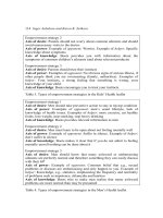
Figure 7.7 Interdigitated capacitor’s
|
S
11
|
and
|
S
21
|
responses.
7.2 Design Considerations
In this section we discuss several design considerations such as compact size,
high-voltage operation, multilayer structure, and voltage tunable capacitor.
7.2.1 Compact Size
The capacitor size can be reduced by reducing the dimensions of the structure
or by using a high dielectric constant value substrate. The achievable Q -value
and fabrication photoetching limit on the minimum line width and separation
dictate the size of the capacitor. For ceramic and GaAs substrates, these limits
are about 12 and 6
m, respectively. It is well known that the wavelength of
a signal is inversely proportional to the square root of the dielectric constant
of the medium in which the signal propagates. Hence, increasing the dielectric
constant of the medium a hundred-fold will reduce the component dimensions
240 Lumped Elements for RF and Microwave Circuits
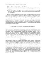
Figure 7.8 Interdigitated capacitor’s ∠S
11
and ∠S
21
responses.
Table 7.2
Physical Dimensions and Equivalent Model Values for Interdigital Capacitors
Physical Dimensions INDIG80 INDIG180 INDIG300 INDIG400 UNITS
Finger length, ᐉ 80 180 300 400
m
Finger width, W 12 12 12 12
m
Finger spacing, side, S 8888
m
Finger spacing, end, S ′ 12 12 12 12
m
Finger thickness, t 5555
m
Number of fingers, N 20 20 20 20
m
Substrate thickness, h 125 125 125 125
m
Capacitance, C 0.126 0.252 0.405 0.527 pF
Inductance, L 0.001 0.025 0.064 0.101 nH
Resistance, R
dc
1.89 0.850 0.500 0.441 ⍀
Shunt capacitance, C
s
0.028 0.052 0.080 0.104 pF
241
Interdigital Capacitors
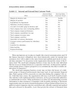
Figure 7.9 The measured performance of an interdigital capacitor compared with the present
model and Touchstone model: (a) reflection coefficient and (b) transmission coeffi-
cient.
by a factor of 10. This simple concept is being exploited extensively as distributed
circuit technology is being adopted at RF and lower microwave frequencies.
7.2.2 Multilayer Capacitor
Gevorgian et al. [22] have reported closed-form expressions for interdigital
capacitors, on two- and three-layered substrates, using conformal mapping
242 Lumped Elements for RF and Microwave Circuits
technique. Figure 7.10 shows the interdigital capacitor configuration, and the
total capacitance is given by
C = C
3
+ C
n
+ C
end
(7.12)
where C
3
, C
n
, and C
end
represent the three-finger capacitance, capacitance of
the periodical (n − 3) structure, and a correction term for the fringing fields of
the ends of the strips, respectively. Closed-form expressions for these capacitance
components are given next.
C
3
capacitance:
C
3
= 4
⑀
0
⑀
e3
K (k
′
03
)
K (k
03
)
ᐉ (7.13)
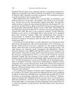
Figure 7.10 (a) Physical layouts and (b) cross-sectional view of the interdigital capacitor.
(From: [22]. 1996 IEEE. Reprinted with permission.)
243
Interdigital Capacitors
where ᐉ is the length of strip fingers and
⑀
e3
= 1 + q
13
⑀
1
− 1
2
+ q
23
⑀
2
−
⑀
1
2
+ q
33
⑀
3
− 1
2
(7.14a)
q
i3
=
K (k
i3
)
K (k
′
i3
)
K (k
′
03
)
K (k
03
)
, for i = 1, 2, 3 (7.14b)
k
03
=
S
S + 2g
√
1 −
ͩ
(S + 2g)
(S + 2S
1
+ 2g)
ͪ
2
1 −
ͩ
S
(S + 2S
1
+ 2g)
ͪ
2
(7.14c)
k
i3
=
sinh
ͩ
S
2h
i
ͪ
sinh
ͩ
(S + 2g)
2h
i
ͪ
и
√
1 − sinh
2
ͫ
(S + 2g)
2h
i
ͬ
⁄
sinh
2
ͫ
(S + 2S
1
+ 2g)
2h
i
ͬ
1 − sinh
2
ͫ
S
2h
i
ͬ
⁄
sinh
2
ͫ
(S + 2S
1
+ 2g)
2h
i
ͬ
(7.14d)
and k
′
i3
=
√
1 − k
2
i3
, i = 1, 2, 3. In the preceding formulas, S
1
= S should be
used where the widths of the external and middle fingers are the same.
C
n
capacitance:
C
n
= (n − 3)
⑀
0
⑀
en
K (k
0
)
K (k
′
0
)
ᐉ (7.15)
where
⑀
en
= 1 + q
1n
⑀
1
− 1
2
+ q
2n
⑀
2
−
⑀
1
2
+ q
3n
⑀
3
− 1
2
(7.16a)
q
in
=
K (k
in
)
K (k
′
in
)
K (k
′
0
)
K (k
0
)
, for i = 1, 2, 3 (7.16b)
244 Lumped Elements for RF and Microwave Circuits
k
in
=
sinh
ͩ
S
2h
i
ͪ
sinh
ͩ
(S + g)
2h
i
ͪ
и
√
cosh
2
ͩ
(S + g)
2h
i
ͪ
+ sinh
2
ͩ
(S + g)
2h
i
ͪ
cosh
2
ͩ
S
2h
i
ͪ
+ sinh
2
ͩ
(S + g)
2h
i
ͪ
(7.16c)
C
end
capacitance:
C
end
= 4ns(2 +
)
⑀
0
⑀
eend
K (k
0end
)
K (k
′
0end
)
(7.17)
where
⑀
eend
= 1 + q
1end
⑀
1
− 1
2
+ q
2end
⑀
2
−
⑀
1
2
+ q
3end
⑀
3
− 1
2
(7.18a)
k
0end
=
x
x + 2g
end
√
1 −
ͩ
(x + 2g
end
)
(x + w + 2g
end
)
ͪ
2
1 −
ͩ
x
(x + w + 2g
end
)
ͪ
2
(7.18b)
where x ≅ 0.5S. The effect of strip thickness t can be accounted for when the
inductor and the gap are replaced by 2S = 2S ′+⌬t and 2g = 2g ′−⌬t, where
⌬t =
t
ͫ
1 + ln
8
S ′
t
ͬ
and 2S ′ and 2g ′ are the physical width of the strip and the gap between them.
7.2.3 Q -Enhancement Techniques
The Q-factor of interdigital capacitors can be enhanced by using high-conductiv-
ity conductors and low-loss tangent dielectric substrate materials. Other
Q-enhancement techniques include suspended substrate, multilayer structure,
and micromachining. These are briefly discussed in the following subsections.
7.2.3.1 Suspended Substrate
The suspended-substrate technique provides a lower loss than the conventional
microstrip structure. Figure 7.11(a) shows a suspended-substrate interdigital
245
Interdigital Capacitors
Figure 7.11 (a) Suspended-substrate interdigital capacitor and (b) multilayer interdigital
capacitor.
capacitor. By selecting the proper substrate thickness and air spacing between
the substrate and ground plane, one can reduce the capacitor loss by a factor
of 25% to 50%. The EM simulated performance of a suspended-substrate
interdigital capacitor is compared with that for a conventional interdigital capaci-
tor in Table 7.3. The capacitor dimensions are W = 20
m, S = S ′=10
m,
ᐉ ′=20
m, ᐉ = 600
m, h = 100
m, and N = 9. The conductors are
4-
m-thick gold.
7.2.3.2 Multilayer Microstrip
The Q-factor of an interdigital capacitor can also be enhanced by using a
modified microstrip structure, as shown in Figure 7.11(b). This structure is
compatible with the standard MMIC fabrication process. The strip conductor
is fabricated on a thin polyimide dielectric layer, which is placed on top of a
GaAs substrate. This allows more of the electric flux lines in the air and resembles
a suspended-substrate microstrip line, which has much lower dissipation loss
than a conventional microstrip. Another way to think of this is that, instead
of inserting 50 to 75
m of additional GaAs beneath the line, we have inserted
a thinner layer of polyimide (a material with lower permittivity) in order to
reduce the dissipation loss. This fabrication technique has also been used to
improve the performance of single-layer and multilayer inductors as discussed
in Chapter 3. The performance of a multilayer interdigital capacitor is compared
with that of conventional and suspended-substrate interdigital capacitors in
Table 7.3. Here the dielectric under the conductors is 10-
m polyimide
(
⑀
r
= 3.2), but the other parameters are the same. In this example, both of
these techniques reduce the interdigital series capacitance by a factor of 3.2.
7.2.3.3 Micromachined Technique
The Q of interdigital capacitors on Si substrate is drastically improved by using
the micromachining technique [23] as discussed in Section 3.1.5, in which the
246 Lumped Elements for RF and Microwave Circuits
Table 7.3
High-Frequency EC Model Parameters of Standard, Suspended-Substrate and Multilayer Interdigital Capacitors, with GaAs Substrate Thickness
of 100
m
Capacitor Qf
res
Configuration L ′ (nH) C ′ (pF) R
dc
R
ac
R
d
C
S1
(pF) C
S2
(pF) C
S3
(pF) at 10 GHz (GHz)
Standard 0.100 0.695 0.011 0.0085 0.0010 0.068 0.188 0.025 398 19.11
Suspended substrate 0.106 0.220 0.011 0.0095 0.0011 0.029 0.093 0.002 1,735 33.00
Multilayer 0.110 0.225 0.011 0.0095 0.0015 0.045 0.156 0.004 1,533 30.6
Note: The EC model used is shown in Figure 7.3(b) and R ′=R/2, where R is given by (3.14).
247
Interdigital Capacitors
parasitic substrate loss is reduced by removing Si below the interdigital structure.
This approach reduces the parasitic capacitance by a factor of
⑀
r
and results in
better millimeter-wave circuits. However, micromachining techniques also
reduce the interdigital series capacitance approximately by a factor of (1 +
⑀
r
)/2.
7.2.4 Voltage Tunable Capacitor
The voltage tunability of interdigital capacitors is achieved by using ferroelectric
materials such as barium strontium titanate or strontium titanate. The properties
of ferroelectric materials were discussed in Section 6.2.5. A voltage tunable
structure could be realized either using bulk material or by employing thin films
as shown in Figure 7.12. The latter configuration is compatible with MIC
technology and can be realized using widely used thin-film deposition techniques.
In the thin-film case, the voltage required to change the material dielectric
constant values is lower than that used for the bulk material configuration. The
dielectric strength for such materials is in the range of a few volts per micron,
which means that the films must be more than 10
m thick to operate such
structures at 5V to 10V, before breakdown occurs. Relatively higher losses and
a lower breakdown voltage limit the power levels of such structures. Such
capacitors can be designed using the analysis discussed in the previous section.
Figure 7.12 Field configurations between interdigital fingers: (a) bulk ferroelectric substrate
and (b) thin-film ferroelectric on a dielectric substrate.
248 Lumped Elements for RF and Microwave Circuits
Measured capacitance versus bias voltage and Q-factor versus operating
frequency of an interdigital capacitor on a thin ferroelectric covered substrate
[Figure 7.12(b)] are shown in Figure 7.13 [24]. The ferroelectric thin film of
Sr
0.5
Ba
0.5
TiO
3
was deposited on an MgO substrate. The interdigital structure
has 12 fingers, line width W ≅ 20
m, gap between fingers S ≅ 6
m, and
Figure 7.13 (a) Capacitance versus bias voltage at 1, 3, and 5 GHz, and (b) Q-factor versus
frequency at various bias voltages of a Sr
0.5
Ba
0.5
TiO
3
thin-film interdigital capacitor
on an MgO substrate. (From: [24]. 1999 John Wiley. Reprinted with permission.)
249
Interdigital Capacitors
finger length ᐉ ≅ 150
m. At 5 GHz, the capacitance value varied by 40%
and the Q-value by 100% when the structure was biased from 0 to 40V.
7.2.5 High-Voltage Operation
Conventional interdigitally coupled line structures are capable of handling volt-
ages of less than 200V, depending on the fabrication tolerances and humidity
[25]. To increase the protection against voltage breakdown across the gap, an
overlay of silicon rubber as shown in Figure 7.14 has been used. Because
dielectric loading modifies the electrical characteristics of the coupled line,
accurate design or simulation methods such as EM simulators are required to
determine the new parameters. A dc block fabricated on RT/duroid substrate
with spacing S = 50
m and width W = 60
m achieved a breakdown voltage
of more than 4.5 kV. Breakdown generally occurs at one of the open ends of
the coupled lines [25].
7.3 Interdigital Structure as a Photodetector
An interdigital structure (Figure 7.1) on a semi-insulating GaAs substrate can
be realized as a photodetector. When a dc voltage that is much higher than the
threshold for electron velocity saturation is applied across the electrodes of an
interdigital structure, the incident photon energy is absorbed by the GaAs
Figure 7.14 Top and side views of high-voltage dc block showing high-voltage insulator
dielectric.
250 Lumped Elements for RF and Microwave Circuits
material, producing electron-hole pairs [26]. These charge carriers induce electric
current between the electrodes, giving rise to the photodetection effect. In such
structures, the semiconductor is usually undoped, the photon energy is larger
than the bandgap of the semiconductor, and the dark current is lower than in
photoconductive detectors. In an interdigital structure, each TiAu electrode
makes a Schottky diode, resulting in a back-to-back diode configuration. When
a voltage is applied across the electrodes, one diode is forward biased and the
other is reverse biased, giving rise to reduced dark current.
A typical interdigital photodetector consists of multilayer GaAs layers as
shown in Figure 7.15(a). The multilayer structure comprises a 0.1-
m-thick
intermediate growth temperature (IGT) GaAs layer grown at 350°C on a 0.4-
m-
thick GaAs buffer layer placed on a semi-insulating GaAs substrate. Both layers
are of undoped GaAs type. The fingers have line width W = 4
m, line spacing
S = 5
m, and an active area of 300 × 300
m
2
.
Figure 7.15 (a) Cross-sectional view of an interdigital photodetector and (b) measured pho-
tocurrent versus input optical power.
251
Interdigital Capacitors
The structure was tested using 0.85-
m wavelength optical power. The
devices were biased at 10V. Figure 7.15(b) shows the measured photocurrent
response as a function of optical power. This device can also be used as an
electron detector [26].
References
[1] Alley, G. D., ‘‘Interdigital Capacitors and Their Application in Lumped Element Micro-
wave Integrated Circuits,’’ IEEE Trans. Microwave Theory Tech., Vol. MTT-18, December
1970, pp. 1028–1033.
[2] Hobdell, J. L., ‘‘Optimization of Interdigital Capacitors,’’ IEEE Trans. Microwave Theory
Tech., Vol. MTT-27, September 1979, pp. 788–791.
[3] Esfandiari, R., D. W. Maki, and M. Sircusa, ‘‘Design of Interdigitated Capacitors and
Their Application to GaAs Filters,’’ IEEE Trans. Microwave Theory Tech., Vol. MTT-31,
January 1983, pp. 57–64.
[4] Joshi, J. S., J. R. Cockril, and J. A. Turner, ‘‘Monolithic Microwave Gallium Arsenide
FET Oscillators,’’ IEEE Trans. Electron Devices, Vol. ED-28, February 1981, pp. 158–162.
[5] Pettenpaul, E., et al., ‘‘CAD Models of Lumped Elements on GaAs Up to 18 GHz,’’
IEEE Trans. Microwave Theory Tech., Vol. 36, February 1998, pp. 294–304.
[6] Bahl, I. J., and P. Bhartia, Microwave Solid State Circuit Design, New York: John Wiley,
1988, Chap. 2.
[7] Sadhir, V., I. Bahl, and D. Willems, ‘‘CAD Compatible Accurate Models for Microwave
Passive Lumped Elements for MMIC Applications,’’ Int. J. Microwave and Millimeter
Wave Computer Aided Engineering, Vol. 4, April 1994, pp. 148–162.
[8] Gupta, K. C., et al., Microstrip Lines and Slotlines, 2nd ed., Norwood, MA: Artech House,
1996, Chap. 8.
[9] Wilson, K., ‘‘Other Circuit Elements for MMICs,’’ GEC J. Research (Special Issue on
Monolithic Microwave Integrated Circuits), Vol. 4, 1986, 126–133.
[10] Ladbrooke, P. H., MMIC Design GaAs FETs and HEMTs, Norwood, MA: Artech House,
1989.
[11] Zhu, L., and K. Wu, ‘‘Accurate Circuit Model of Interdigital Capacitor and its Application
to Design of New Quasi-Lumped Miniaturized Filters With Suppression of Harmonic
Resonance,’’ IEEE Trans. Microwave Theory Tech., Vol. 48, March 2000, pp. 347–356;
also see correction in Trans. MTT, Vol. 50, October 2002, p. 2412.
[12] Sonnet Software, Liverpool, NY: EM.
[13] Maxwell SV, Pittsburgh: Ansoft.
[14] High Frequency Structure Simulator, Santa Rosa, CA: Agilent.
[15] LINMIC + Analysis Program, Ratingen, Germany: Jansen Microwave.
[16] MSC/EMAS, Milwaukee, WI: MacNeal Schwendler.
252 Lumped Elements for RF and Microwave Circuits
[17] IE3D, San Francisco: Zeland Software.
[18] Kattapelli, K., J. Burke, and A. Hill, ‘‘Simulation Column,’’ Int. J. Microwave and Millimeter
Wave Computer-Aided Engineering, Vol. 3, January 1993, pp. 77–79.
[19] Rautio, J., ‘‘Simulation Column,’’ Int. J. Microwave and Millimeter Wave Computer-Aided
Engineering, Vol. 3, January 1993, pp. 80–81.
[20] Zhang, J. X., ‘‘Simulation Column,’’ Int. J. Microwave and Millimeter Wave Computer-
Aided Engineering, Vol. 3, July 1993, pp. 299–300.
[21] Mongia, R., I. Bahl, and P. Bhartia, RF and Microwave Coupled-Line Circuits, Norwood,
MA: Artech House, 1999.
[22] Gevorgian, S. S., et al., ‘‘CAD Models for Multi-Layered Substrate Interdigital Capacitors,’’
IEEE Trans. Microwave Theory Tech., Vol. 44, June 1996, pp. 162–164.
[23] Chi, C Y., and G. M. Rebeiz, ‘‘Planar Microwave and Millimeter-Wave Lumped Elements
and Coupled-Line Filters Using Micro-Machining Techniques,’’ IEEE Trans. Microwave
Theory Tech., Vol. 43, April 1995, pp. 730–738.
[24] Patel, D. P., J. M. Pond, and J. B. L. Rao, ‘‘Microwave Ferroelectric Devices,’’ Wiley
Encyclopedia of Electrical and Electronics, Vol. 13, New York: John Wiley, 1999,
pp. 109–118.
[25] Koscica, T. E., ‘‘Microstrip Quarter-Wave High Voltage DC Block,’’ IEEE Trans. Micro-
wave Theory Tech., Vol. 41, January 1993, pp. 162–164.
[26] Yost, T. A., A. Madjar, and P. R. Herczfeld, ‘‘Frequency Response Mechanisms for the
GaAs MSM Photodetector and Electron Detector,’’ IEEE Trans. Microwave Theory Tech.,
Vol. 49, October 2001, pp. 1900–1907.
8
Resistors
8.1 Introduction
Lumped-element resistors [1–13] are used in RF, microwave, and millimeter-
wave ICs. The applications include terminations, isolation resistors, feedback
networks, lossy impedance matching, voltage dividers, biasing elements, attenua-
tors, gain equalizing elements, and as stabilizing or damping resistors that prevent
parasitic oscillations. The design of these resistors requires a knowledge of (1)
sheet resistance, (2) thermal resistance, (3) current-handling capacity, (4) nomi-
nal tolerances, and (5) temperature coefficient of the film. These resistors can
be realized either by depositing thin films of lossy material on a dielectric
base using thin-film, thick-film, or monolithic technologies or by employing
semiconductor films on a semi-insulating substrate between two electrodes.
Nichrome and tantalum nitride are the most popular and useful film materials
for thin-film resistors (thickness: 0.05–0.2
m).
The resistance R value of a planar resistor, as shown in Figure 8.1, depends
on the material properties and its dimensions, and is given by
R =
ᐉ
A
=
ᐉ
Wt
=
ᐉ
Wt
(8.1)
where
is the bulk resistivity of the material expressed in ⍀-m,
is the bulk
conductivity expressed in S/m, ᐉ is the length of the resistor along the direction
of current flow (Figure 8.1), W is the width, t is the thickness, A is the cross-
sectional area, and dimensions are in meters. The resistance can also be calculated
from the sheet resistance R
s
(ohms/square) of the resistive film (for given thickness
t) using the following relation:
253
254 Lumped Elements for RF and Microwave Circuits
Figure 8.1 Geometry of a planar resistor.
R = R
s
ᐉ
W
, where R
s
=
/t =
1
t
(8.2)
For given material R
s
, the resistance can easily be calculated from the num-
ber of squares of width in total length. For example, a line of width 50
m
that is 1,000
m long has 2.5 times less resistance than a line of width 20
m
that is also 1,000
m long. Thus the key in increasing the resistance is to keep
the number of metallization squares as large as possible in a given length. Fig-
ure 8.2 shows six squares between terminals 1 and 2 and if the R
s
value is
10 ⍀/square, the total resistance is 60⍀.
When a voltage is applied across a resistor (Figure 8.3), the current flowing
through it depends on the resistance or conductance (reciprocal of resistance)
value, or when a current flows through the resistor, the voltage developed across
its terminals again depends on its resistance value.
The ratio of voltage and current is equal to the resistance R, also known
as Ohm’s law:
R =
V
I
⍀ (8.3)
where voltage V and current I are expressed in volts and amperes, respectively.
Figure 8.2 Resistance calculation representation of a resistor from sheet resistance.
255
Resistors
Figure 8.3 Electrical representation of a resistor.
The power dissipated, P
dc
, in the resistor due to the applied voltage is
given by
P
dc
= V и I =
V
2
R
= I
2
R (8.4)
where unit of P
dc
is in watts. An ideal resistor, or a resistor with length very
small compared to the operating wavelength, dissipates only electric energy and
constitutes negligible electric and magnetic stored energies because of negligible
associated parasitic capacitance and inductance, respectively.
Like low-frequency resistors, RF and microwave resistors must have the
following properties:
•
Sheet resistance in the range of 1 to 1,000 ⍀/square;
•
Low temperature coefficient of resistance;
•
Good stability;
•
Required power dissipation capability;
•
Low parasitics.
Table 13.4 in Chapter 13 provides some of the resistive materials used
in the fabrication of resistors. From those materials specified, nichrome and
tantalum nitride are the most widely used. The exact properties of these materials
vary with fabrication process and thickness.
8.2 Basic Definitions
In this section various terms used to specify a resistor are defined.
8.2.1 Power Rating
The power rating of a resistor is defined as the maximum power a resistor can
withstand without affecting its base value and reliability. Power rating depends
256 Lumped Elements for RF and Microwave Circuits
on its area (larger area can sink more dissipated power) and ambient temperature.
High-power rated resistors have large areas and appreciable parasitics, which
can affect their RF performance at microwave frequencies.
8.2.2 Temperature Coefficient
The rate of change of resistor value with temperature is known as the temperature
coefficient of resistors (TCR) or simply TC and is expressed in percent per degree
Celsius or parts per million per degree Celsius (ppm/°C). When the resistance
increases with increasing temperature, the TC value has a positive sign; if it
decreases, the TC value has a negative sign. The resistor’s temperature depen-
dence is given by
R
OT
= R
RT
+ TC(T
OT
− T
RT
) (8.5)
where OT and RT denote the operating and room or ambient temperature,
respectively. If a resistor has +TC value of 40 ppm/°C, the resistance value
will increase with temperature by about 0.4% at 125°C; when the ambient
temperature is 25°C, a 100-⍀ resistor at room temperature will be about 100.4⍀
at 125°C.
8.2.3 Resistor Tolerances
Variations in the specified resistor values in a batch or batch to batch are
expressed in terms of resistor tolerances. In general, depending on the resistor
manufacturing technology and the application, resistor tolerances in the range
of ±1%, ±5%, ±10%, or ±20% can be achieved.
8.2.4 Maximum Working Voltage
The maximum voltage one can apply across a resistor without affecting its
resistance value is termed the maximum working voltage. The maximum working
voltage depends on the resistor material, allowed resistance deviations from a
small voltage value, and physical configuration. The voltage coefficient of a
resistor in percentage is expressed as
Voltage coefficient =
R − R
m
RV
m
100 (8.6)
where R and R
m
are the resistance values at a very low voltage and the maximum
allowed voltage V
m
, respectively.
257
Resistors
8.2.5 Maximum Frequency of Operation
A resistor value also depends on its frequency of operation. Planar resistors have
associated parasitic reactances and their values increase with frequency, affecting
the net resistance value. At a certain frequency, the capacitive and inductive
reactances become equal and give rise to self-resonance. This will be discussed
in detail in Section 8.3.
8.2.6 Stability
In most applications, the change of resistance value with time is not a desirable
characteristic. The drift in resistance value over an extended time period is
expressed in terms of stability of the resistor. Typically, thin-film resistors might
change within ±0.2% during a 5-year period.
8.2.7 Noise
Every resistor has Johnson noise proportional to its resistance value due to
unwanted random voltage fluctuations generated within the resistor. Depending
on the resistor material and its fabrication, the resistors also have additional noise
sources. For example, in a monolithic thin-film resistor on a GaAs semiconductor
substrate, additional noise is a result of imperfect ohmic contact and the resistor
film.
Johnson noise, also known as ‘‘white’’ or thermal noise, depends on the
temperature and is independent of frequency of operation. The rms voltage v
n
expressed in volts is given by
v
n
= (4kRT⌬f )
1/2
(8.7)
where k is the Boltzmann constant (1.38 × 10
−
23
J/K), R is the resistance in
ohms, T is the operating temperature in kelvins, and ⌬f is the bandwidth in
hertz over which the noise voltage is measured.
8.2.8 Maximum Current Rating
Each resistor has a specified maximum current rating above which the resistor
might fail due to current density being higher than the allowed value.
8.3 Resistor Types
The manufacturing of LE resistors can be divided into three categories: chip,
monolithic, and multichip module resistors. These are briefly discussed in this
section.
258 Lumped Elements for RF and Microwave Circuits
8.3.1 Chip Resistors
Thin-film and thick-film hybrid technologies have been used to manufacture
chip resistors for low-power and high-power applications. In thin-film hybrid
technology, resistive thin films consisting of nichrome (NiCr) or tantalum
nitride (TaN) are deposited on alumina for low-power applications and on
beryllia or aluminum nitride for high-power applications.
Thick-film resistors are manufactured using various compositions of ruthe-
nium dioxide (RuO
2
) paste and a screen printing process. Sheet resistance values
ranging from 1⍀ to 10 k⍀ per square are obtained by mixing RuO
2
with silver
(Ag) and palladium (Pd) conducting particles for values less than 100 ⍀/square,
and by mixing RuO
2
with Ag lead ruthenate and bismuth ruthenate for values
higher than 100 ⍀/square. Commonly used base substrate materials are alumina,
beryllia, and aluminum nitride. More detailed discussion of this subject is
provided in Chapter 13.
8.3.2 MCM Resistors
MCM technologies include PCBs, cofired ceramic, and thin film on silicon.
In PCB technology, the resistor material is deposited on a polyimide layer
and covered with another polyimide film for encapsulation. The electrode
connections through contact holes are made with copper using photolithography
techniques. The resistive film materials used are NiCr, TaN, and CrSi. The
other two MCM technologies use resistor fabrication as discussed for hybrid
and monolithic technologies.
8.3.3 Monolithic Resistors
Resistors are an integral part of MICs and can be realized either by depositing
thin films of lossy metal or by employing bulk semiconductor films on a semi-
insulating substrate as shown in Figure 8.4.
Nichrome and tantalum nitride are the most popular and useful film
materials for thin-film resistors (thickness: 0.05–0.2
m). Resistors based on
semiconductor (e.g., GaAs or Si) films can be fabricated by forming an isolated
land of semiconductor conducting layer (thickness: 0.05–0.5
m). Both types
are fabricated by defining the desired pattern by photolithography. Factors such
as resistance value, tolerance, reproducibility, and power handling are determined
based on the resistor type. Table 8.1 summarizes typical parameters of monolithic
resistors fabricated on GaAs substrate.
In monolithic resistors, the total resistance is the sum of resistive film and
the resistance of the two ohmic contacts and is given as
R = R
s
ᐉ
W
+ 2R
sc
ᐉ
c
W
c
(8.8)
259
Resistors
Figure 8.4 Planar resistors: (a) thin film, (b) mesa, and (c) implanted.
where R
sc
, ᐉ
c
and W
c
are the sheet resistance, length, and width of the ohmic
contacts, respectively.
8.3.3.1 Thin-Film Resistors
Thin-film resistor materials are of metal types such as GeAu, Ta, Ti, Cr, and
NiCr or of composite material type such as TiWN, TaN, and Ta
2
N. Thin-
film resistors are typically 0.1 to 0.4
m thick and have limited current-
carrying capability. The maximum current density allowed by electromigration
requirements in thin films is about 3 × 10
5
A/cm
2
. Therefore, the current
density per unit width for such resistors is of the order of 0.3 to 1.2 mA/
m.
8.3.3.2 Bulk Semiconductor Resistors
Bulk semiconductor resistors form an integral part of MIC fabrication and no
additional fabrication steps are required. The sheet resistance (R
s
) value of such
resistors depends on the doping of the material such as n
−
, n, and n
+
. For
GaAs semiconductors, the typical value of R
s
lies between 100 and 1,500
⍀/square, and is lowest for n
+
layers and highest for n
−
layers. However, GaAs
resistors have four potential problems: change in surface potential, low current
260 Lumped Elements for RF and Microwave Circuits
Table 8.1
Typical Room Temperature Parameters of Monolithic Resistors Fabricated on GaAs Substrate
Sheet Resistance Nominal Maximum Current
Resistor Type Material Thickness (
m) Value (ohm/square) Tolerance (%) TCR (ppm/؇C) (mA/
m)
Thin film TiWN 0.18 10.8 ±10 +100 1.0
Implanted n
+
GaAs 0.2 140.0 ±20 +2,000 0.6
Ohmic Ni/Ge/Au 0.14 0.9 ±30 +100 0.4
Metal 1 Ti/Pd/Au 0.60 0.05 ±20 +100 1.0
261
Resistors
saturation, Gunn domain formation, and large temperature coefficient. These
are briefly discussed next.
Change in Surface Potential
The first potential problem is the change in surface potential under resistor
areas over an extended period of time. Such drifts affect the sheet resistance of
the resistor. A dielectric protection layer over such resistors minimizes this
change.
Low Current Saturation
Bulk resistors have nonlinear behavior at high electric fields as a result of carrier
velocity saturation. The electric field at which this phenomenon takes place is
known as the critical electric field and its value for GaAs is 3.3 kV/cm. In
practice, this can be avoided by designing resistor dimensions such that maxi-
mum field strength across the resistor’s electrodes is less than about 2 kV/cm
(0.2 V/
m). Assuming that 10V is a safe operating voltage, the minimum
resistor’s length required is 50
m. If the sheet resistance of an n
+
-type GaAs
layer is 150 ⍀/square, the widths required for 50-, 200-, and 500-⍀ resistors
calculated using W = R
s
ᐉ /R are 150, 37.5, and 15
m, respectively.
Gunn Domains
Gunn domains are formed only above the critical field across the resistor elec-
trodes. Because the operating electric field across the bulk resistors is much
less than critical field, the occurrence of Gunn domains in such resistors is
nonexistent.
Temperature Coefficient
The temperature coefficient of GaAs resistors is positive and large. The approxi-
mate value is about 300 ppm/°C and is about 10 times higher than the values
for thin-film resistors. This results in appreciable increase in resistance value
with temperature. In most MMIC applications, bulk resistors are used when
their value is not critical to the circuit design; otherwise, one has to include
temperature dependence in the design or some temperature compensation tech-
niques must be utilized to offset the change in resistance with temperature.
Because bulk resistors or GaAs resistors are fabricated from single-crystal
GaAs material, the electromigration phenomenon is not present, because this
phenomenon deals with crystalline grain boundaries.
8.3.3.3 Parasitic Effects
A problem common to all planar resistors is the parasitic capacitance attributable
to the underlying dielectric region and the distributed inductance, which makes
such resistors exhibit a frequency dependence at high frequencies. If the substrate
262 Lumped Elements for RF and Microwave Circuits
has a ground plane, one can determine the frequency dependence by treating
the resistor as a section of a very lossy microstrip line. Figure 8.5 shows how
the VSWR increases dramatically at low values of R
SH
because the length of
the resistor becomes too large.
Also shown in Figure 8.5 is the thermal resistance. Clearly, a trade-off is
necessary between VSWR and thermal resistance. The smaller the resistor size
meeting the current-handling and thermal requirements the better the electrical
performance due to lower parasitic effects.
8.3.3.4 Power Handling
The power-handling capacity of monolithic resistors is limited due to burnout
of the thin film by overheating. The power-handling capacity of monolithic
resistors can be determined in a way similar to that of microstrip lines (discussed
in Chapter 14). In this case, the resistor strip is considered to be a lossy microstrip
line. Because the loss in the resistor conductor is much higher than the dielectric
loss, only conductor loss is considered in the calculation of power dissipated.
The temperature difference ⌬T (in degrees Celsius) between the resistor film
and the back side of the substrate due to P
dc
(in watts) power dissipated in the
resistor is given by
⌬T = P
dc
R
TH
= P
dc
h
KA
(8.9)
Figure 8.5 Thermal resistance and VSWR of a planar resistor as a function of sheet resistance
and frequency.
263
Resistors
where R
TH
is the thermal resistance, A is the equivalent area of the resistor of
length ᐉ, h is the thickness, and K is the thermal conductivity of the substrate.
Dimensions of h, A , and K are meters, square meters, and W/m-°C, respectively.
The resistor area is given by
A = W
e
(ᐉ + 2ᐉ ′) (8.10)
where ᐉ ′ is the length of the ohmic contact used to connect the resistor film
to other circuitry and W
e
is the effective width calculated from the parallel plate
waveguide model. Approximately W
e
= W + 2h.IfR
s
is the sheet resistance of
the film, the total resistance R is given by
R = R
s
ᐉ
W
(8.11)
From (8.10) and (8.11),
A = (W + 2h)
ͩ
R
R
s
W + 2ᐉ ′
ͪ
(8.12)
From (8.9) and (8.12),
W
2
+ pW − q = 0 (8.13)
where
p = 2h +
2ᐉ ′R
s
R
(8.14a)
q =
R
s
h
R
ͫ
P
dc
K⌬T
− 4ᐉ ′
ͬ
(8.14b)
Equation (8.14b) is valid for positive values of q .
The solution of (8.13) for positive a value of W is
W =
−p +
√
p
2
+ 4q
2
(8.15)
Thus, the required resistor width for given power dissipation and resistance
value can be calculated from (8.15). Consider an example of a 50-⍀ resistor