Báo cáo lâm nghiệp: "Discrimination of coated carbide tools wear by the features extracted from parallel force and noise level" potx
Bạn đang xem bản rút gọn của tài liệu. Xem và tải ngay bản đầy đủ của tài liệu tại đây (395.96 KB, 6 trang )
731
Ann. For. Sci. 61 (2004) 731–736
© INRA, EDP Sciences, 2004
DOI: 10.1051/forest:2004070
Note
Discrimination of coated carbide tools wear by the features
extracted from parallel force and noise level
Wayan DARMAWAN
a,b
*, Chiaki TANAKA
c
a
Faculty of Forestry, Bogor Agricultural University, Kampus IPB Darmaga, Bogor 16680, Indonesia
b
Current address: Dept. Teknologi Hasil Hutan, Fakultas Kehutanan, Kampus IPB Darmaga, Bogor 16680, Indonesia
c
Faculty of Science and Engineering, Shimane University, Nishikawatsu-cho 1060, Matsue, Shimane 690-8504, Japan
(Received 27 February 2003; accepted 2 July 2004)
Abstract – Coated carbide tools were tested for turning of wood-chip cement board. Coating materials, which were synthesized on the P30
carbide substrate, are titanium carbonitride, titanium nitride, chromium nitride, and titanium nitride/aluminum nitride. Cutting tests were
performed at cutting speeds of 30, 40, 50 and 60 m/s, depth of cut of 1 mm, and feed of 0.05 mm/rev. Wear, parallel force and noise level were
measured at every specified cutting length. The purpose was to discriminate various stages of wear of the coated carbide tools by the features
extracted from parallel force and noise level. The results of the study show that both the parallel force and noise level generated by the tools
tested were observed to increase linearly with increasing the tools wear, and would be good parameters for monitoring the tool wear. The
parallel force and the noise level of the cutting tools also increased with increasing the cutting speeds for every specified cutting length. The
parallel force became more sensitive than the noise level for monitoring the tool wear when the cutting speed was increased.
coated carbide tool / parallel force / noise level / wood-chip cement board / cutting speed
Résumé – Estimation de l’usure d’outils carbures revêtus à partir de paramètres extraits de l’analyse du bruit et des efforts de coupe.
Des outils carbure ont été testés dans un essai de tournage de panneaux bois ciment. Le carbonite, de titane, le nitride de titane, le nitride de
chrome et le complexes nitride de titane/nitride d’aluminium ont été utilisés comme matériaux de revêtement sur un substrat carbure de type
P30. Les essais de coupe ont été réalisés à des vitesses de 30, 40, 50 et 60 m/s avec une profondeur de coupe de 1 mm et une avance de 0,05 mm
par tour. L’usure, la composante de l’effort de coupe parallèle au mouvement relatif bois/outil et le niveau de bruit ont été menés pour chaque
longueur de coupe retenue. L’objectif était de distinguer différentes étapes d’usure de l’outil revêtu à partir de l’analyse des signaux d’efforts
et de bruit. L’étude a montré que la composante parallèle de l’effort de coupe et le niveau de bruit augmentaient tous deux de manière linéaire
avec l’usure mesurés sur la face de dépouille, pour tous les outils testés. Ce sont potentiellement de bons paramètres pour le suivi en ligne de
l’usure de l’outil. Ces deux paramètres augmentent aussi quand la vitesse de coupe augmente, pour toutes les longueurs de coupes utilisées. La
composante parallèle de l’effort de coupe devient un paramètre plus sensible pour suivre l’usure de l’outil quant la vitesse de coupe augmente.
outil carbure revêtu / effort de coupe / niveau de bruit / composite bois ciment / vitesse de coupe
1. INTRODUCTION
Some automatic monitoring systems have been proposed to
achieve a higher productivity in wood processing. Application
of the automatic monitoring system in band-sawing, circular-
sawing, routing, milling and peeling would help the wood
worker in increasing productivity, diagnosing the machine con-
ditions (bearings, chains), predicting the machining imperfect-
ness (washboard, abnormal roughness), and controlling the cut-
ting tool condition (tool edge wear, tool edge damage). Several
parameters (cutting energy [10], cutting force [6], cutting sound
[15], acoustic emission [8], saw vibration [9], cutting temper-
ature [11]) were investigated to be useful for providing infor-
mation to the automatic systems.
Cutting tools are generally replaced or grinded to minimize
the probable consequences of a failure event during the cutting
processes. A wood worker may check or replace the cutting tool
frequently to reduce the probability of an in-process failure, but
as a consequent interrupting the process so frequently is a
decrease in productivity and an increase in tool cost. Though
a skilled worker in woodworking industry can diagnose the
state of tool wear during the cutting processes by the cutting
force, cutting noise, or cutting power consumption with the
help of his experiences, however recently, due to the lack of
those skilled workers and the increasing demands for the pro-
duction techniques for higher efficiency and productivity, it is
necessary to promote an automation in the woodworking indus-
try. For the realization of the automatic mechanical processing
of wood, the in-process monitoring and the diagnosing of the
process is an important technique to be developed.
Cutting forces and noise level have shown great promise in the
monitoring of the extent of tool wear. An excellent correlation
* Corresponding author:
732 W. Darmawan, C. Tanaka
was found to exist between the cutting forces and tool wear [1,
13, 14], and the feasibility of techniques of pattern recognition
using the cutting sound for the discrimination of the various
stages of edge wear was clarified [7]. Another study revealed
that behavior of acoustic emission (AE) signal was found to be
a superior parameter for estimation of wear of the cutting tool
[12]. In those studies, non-coated tools with their various
geometries were experimented.
In another study, coated carbide tools were experimented for
cutting wood based materials, and their wear characteristics
were reported [3–5]. In an effort to provide more information,
the parallel force and noise level of the tools, and their changes
due to the wear were reported in this paper. The regression
equations were applied to discriminate the various stages of
tool wears by the features extracted from the parallel force and
noise level. The purpose is to determine the feasibility of using
parallel force and noise level to monitor the extent of wear of
the coated carbide tools for various cutting speed.
2. MATERIALS AND METHODS
2.1. Coated carbide tools and work material
Specifications of coated carbide tools tested, work material
machined and cutting conditions applied are summarized in Table I,
Table II, Table III respectively. P30 carbide tool [81% WC, 9% (Ti,Ta),
10% Co] used as a substrate was in 12.7 mm long, 12.7 mm wide, and
4.8 mm thick. Some P30 carbides were coated with the single layer
of titanium nitride (TiN), chromium nitride (CrN), titanium carboni-
tride (TiCN) and alternating-multilayer of titanium nitride/aluminum
nitride (TiN/AlN) coatings by PVD method on the rake and clearance
faces. All the coated tools were produced in a standard production line
for experiment.
2.2. Methods
Wear resistance of the coated carbide tools was tested in turning
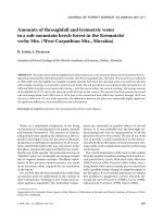
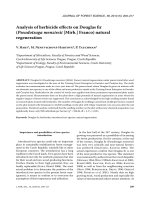
high-density wood-chip cement board. Schematic diagram of the turn-
ing tests is presented in Figure 1. In the figure, wood-chip cement
board in diameter of 300 mm was held on the router spindle of numer-
ical controlled (NC) machine. A tool with its holder, which was
designed to produce cutting angle of –5° and clearance angle of 5°,
was placed on the three component forces of dynamometer that was
held on the table of the NC machine.
Turning was performed by the corner of the cutting edge along the
edge of the disk (work material) with depth of cut of 1 mm. The disk
was fed down into the corner of the cutting edge in the speed of
0.05 mm/rev. When the cutting tools finished one pass of cutting (cut-
ting from bottom face to top face of the disk with cutting length of
about 500 m), the amount of clearance wear on the corner of the cutting
Table I. Specifications of the coated carbide tools.
Cutting tool Thickness
of film (µm)
Hardness (HV) Resistance to oxidation
temperature (°C)
Absorptive capacity of heat energy
(Ws
1/2
/m
2
K)
P30 carbide
TiN coated P30
CrN coated P30
TiCN coated P30
TiN/AlN coated P30
–
3–4
3–4
3–4
3–4
1450
2000
1800
3000
4000
–
750
800
450
930
–
8100
–
13900
6300
Table II. Specifications of the wood-chip cement board.
Thickness (mm) 25
Density (g/cm
3
)1.20
Moisture content (%) 11.6
Compressive strength (N/mm
2
) 23.4
Shear strength (N/mm
2
)3.5
Hardness (N/mm
2
) 50.6
Composition
Wood-chip 25wt%
Cement 75wt%
Table III. Cutting conditions for the carbide tools.
Cutting speed (V) 30, 40, 50, 60 m/s
Feed (F) 0.05 mm/rev
Depth of Cut (D) 1.0 mm
Tool geometry
Wedge angle
Corner radius
90°
0.8 mm
Figure 1. Schematic diagram of the turning test.
Discrimination of tool wear 733
edge, parallel force and noise level were measured. Then, cutting test
was continued on another new disk by replacing the old disk with the
new disk. Testing was stopped up to ten pass of cutting (cutting length
of about 5 km).
2.3. Measurements
All tools were inspected before testing to assure that there are no
surface cracks and chippings of the coating materials on the clearance
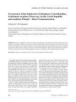
face using an optical video microscope. Measurement of the wear was
made using a measure-microscope as shown in Figure 2. The tools
were also inspected at the final cut using an optical-video microscope
and a scanning electron microscope/energy dispersive spectroscopy
(SEM/EDS) for identification of the mode of the cutting edge failure
and mapping the residuals elements of the worn surfaces.
A precision Sound Level Meter was used for measurement of the
sound level of the audible cutting noise on the C weighting, which is
usually used for measuring the peak of sound pressure level. The
Sound Level Meter was connected to a microphone, which was set up
at the height of the cutting tool edge (about 1000 mm above ground
level) and at a distance of about 1000 mm along a straight line extend-
ing from the cutting tool edge.
Measurement of the parallel force was made by using the three
components force of dynamometer attached on the table of the NC
machine. The three components force of dynamometer was connected
to a strain amplifier and a GP-IB board was used to record and to dis-
play the force during cutting on the personal computer.
3. RESULTS AND DISCUSSION
3.1. Parallel force and noise characteristics
of the coated carbide tools with clearance wear
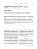
The experimental results indicated that all tools tested show
the same behavior in relationship between parallel force and
clearance wear, and noise level and clearance wear for all cut-
ting speeds performed. For this discussion, the parallel force
and noise level behaviors of the TiN/AlN coated tool are pro-
vided as presented in Figures 3 and 4. These figures give an
indication that the parallel force and the noise level generated
by the tools increased linearly with an increase in the clearance
wear.
Regression equation and its correlation coefficient for the
linears in Figures 3 and 4 are summarized in Table IV. The
regression equations and correlation coefficients for the other
tools are also included in Table IV for comparison. The results
show that the regression coefficients for the parallel force lin-
ears depicted by the tools vary from 0.04 to 0.08, and for the
noise level vary from 0.02 to 0.04. These variations give an
indication that the tool materials (coating materials) deter-
mined the rate of the increase of the parallel force and the noise
level. It appears that TiN coated tool would be more gradual in
the increase of the parallel force compared to the others, which
would be almost the same in the rate of the increase (Tab. IV).
The TiN/AlN coated tool would be more abrupt in the increase
of the noise level compared to the others. However, the regres-
sion coefficients for the parallel force and noise level among
cutting speeds in each tool are almost the same. This means that
each tool would generate almost the same parallel force and
noise level as long as the amounts of clearance wear attained
are the same.
Figure 2. Illustration of clearance wear measurement.
Figure 3. Linear relationships between parallel force and clearance
wear of the TiN/AlN coated tool for various cutting speeds.
Figure 4. Linear relationships between noise level and clearance wear
of the TiN/AlN coated tool for various cutting speeds.
734 W. Darmawan, C. Tanaka
It also appears from the results in Table IV that both the par-
allel force and noise level are high in correlation coefficient
with the clearance wear. Therefore, the variation in the parallel
force and noise level with clearance wear is a good indication
of the extent of wear on the clearance face.
3.2. The effect of cutting speed on the parallel forces
and noise level
The experimental results indicated that the parallel force
increased proportionally with an increase in cutting speed at
every specified cutting length for all tools investigated. For this
discussion, relation between parallel force and cutting speed for
the final cutting length is provided in Figure 5. The increase in
the parallel force with an increase in cutting speed was caused
by larger relaxation of the work material on the clearance face
[2] and greater amount of clearance wear [5], which further
caused high rubbing pressure on the clearance surface of the
coated carbide tools, being attained by the cutting tools for the
high cutting speed.
Table IV. Regression equation and correlation coefficient for the relationship between parallel force, noise level and clearance wear.
Cutting tools Cutting speed (m/s) Parallel force and clearance wear Noise level and clearance wear
Linear equation r Linear equation r
P30 carbide 30 Y = 9.38 + 0.08X 0.97 Y = 83.37 + 0.03X 0.94
40 Y = 12.46 + 0.08X 0.92 Y = 86.41 + 0.02X 0.96
50 Y = 12.68 + 0.07X 0.96 Y = 86.02 + 0.02X 0.92
60 Y = 11.13 + 0.06X 0.95 Y = 86.79 + 0.02X 0.91
TiN/AlN coated 30 Y = 15.00 + 0.06X 0.94 Y = 87.80 + 0.03X 0.89
40 Y = 15.03 + 0.06X 0.96 Y = 87.77 + 0.04X 0.90
50 Y = 15.03 + 0.07X 0.95 Y = 87.68 + 0.04X 0.92
60 Y = 15.38 + 0.08X 0.96 Y = 87.44 + 0.04X 0.89
CrN coated 30 Y = 14.33 + 0.06X 0.87 Y = 84.35 + 0.03X 0.93
40 Y = 15.37 + 0.06X 0.90 Y = 86.67 + 0.02X 0.87
50 Y = 17.44 + 0.05X 0.91 Y = 86.95 + 0.02X 0.96
60 Y = 16.70 + 0.06X 0.96 Y = 87.06 + 0.02X 0.88
TiN coated 30 Y = 16.08 + 0.04X 0.77 Y = 85.74 + 0.03X 0.89
40 Y = 16.71 + 0.04X 0.89 Y = 86.46 + 0.03X 0.92
50 Y = 19.78 + 0.05X 0.79 Y = 87.15 + 0.02X 0.87
60 Y = 18.48 + 0.04X 0.97 Y = 87.21 + 0.02X 0.87
TiCN coated 30 Y = 12.62 + 0.08X 0.90 Y = 85.48 + 0.03X 0.88
40 Y = 15.53 + 0.07X 0.97 Y = 86.40 + 0.03X 0.90
50 Y = 15.80 + 0.05X 0.93 Y = 86.69 + 0.02X 0.98
60 Y = 15.28 + 0.06X 0.92 Y = 86.97 + 0.02X 0.94
Y = parallel force and noise level, X = clearance wear, r = correlation coefficient.
Figure 5. Behaviors of the parallel force of the tools tested with cut-
ting speed for the final cutting length.
Discrimination of tool wear 735
Experimental results in Figure 5 show that the TiN/AlN
coated carbide tool generated the smallest parallel force for all
cutting speeds at the final cutting length among the tools inves-
tigated. This is considered to be due to the fact that the TiN/
AlN coated carbide tool suffered much lower amount of clear-
ance wear at every cutting speed performed compared to the
other tools investigated [5]. On the other hand the other tools
investigated varied slightly in the parallel force as the cutting
speed was increased.
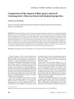
The experimental results also indicated that the noise level
generated by all tools increased proportionally with an increase
in cutting speed for every specified cutting length. In Figure 6,
the noise levels generated by all tools at the final cutting length
are provided for this discussion. The high noise levels gener-
ated during high-speed cutting are probably caused by large
impact force being imposed on the tools for the high-speed cut-
ting. It is also observed from the results in Figure 6 that though
the amount of clearance wear of the TiN/AlN coated carbide
was much lower than the other tools investigated [5], however
its noise level is almost the same as that of the other tools. This
could be due to the extreme hardness of the TiN/AlN coated
tool, which imposed large impact during the cutting.
3.3. Relationship between parallel force and noise level
The results in Figure 7 indicate that the noise level and the
parallel force are close in relationship. The noise level
increased linearly with increasing the parallel force. It could be
considered from the regression equation in Figure 7 that the
tools (in average) would generate about 1 dB noise level when
the parallel force of the tools changed in 2 N for the 30, 40, and
50 m/s cutting speeds, and would generate about 1 dB noise
level when the parallel force changed in 4 N for the 60 m/s cut-
ting speed. This fact gives an indication that the parallel force
became more sensitive compared to the noise level in deter-
mining the clearance wear behavior of the tools investigated
when the cutting speed was increased.
4. CONCLUSIONS
The following conclusions can be drawn based on the find-
ings of this experiment.
1. Both the parallel force and noise level of the tools inves-
tigated increase with increasing the clearance wear, and would
be a good indication for the extent of wear on cutting edge of
the tools.
2. The tool materials (coating materials) are observed to
determine the rate of the increase of the parallel force and the
noise level.
3. Though the coated tools are applied for different cutting
speed, the tools generate almost the same parallel force and
noise level, as long as their amount of clearance wears are same.
4. The parallel force of TiN/AlN coated carbide tool are the
smallest among the tools investigated, however its noise level
is almost the same as that of the other tools investigated for
every specified cutting length.
5. The parallel force becomes more sensitive than the noise
level for monitoring the tool wear when the cutting speed is
increased.
REFERENCES
[1] Axelsson B.O.M., Grundberg S.A., Gronlund J.A., Tool wear when
planning and milling, Measurement methodology and influencing
factors, in: Proceedings of the 11th International Wood Machining
Seminar, 1993, pp. 159–176.
[2] Costes J.P., Larricq P., Towards high cutting speed in wood mill-
ing, Ann. For. Sci. 59 (2002) 857–865.
[3] Darmawan W., Tanaka C., Usuki H., Ohtani T., Wear characteris-
tics of some coated carbide tools when machining hardboard and
wood-chip cement board, J. Wood Ind. 55 (2000) 456–460.
[4] Darmawan W., Tanaka C., Usuki H., Ohtani T., Performance of coated
carbide tools in grooving wood-based materials: Effect of coating
materials and work material on the wear resistance of coated car-
bide tools, J. Wood Sci. 47 (2001) 94–101.
Figure 6. Behaviors of the noise level of the tools tested with cutting
speed for the final cutting length.
Figure 7. Linear relationships between noise level and parallel force
of the tools investigated (in average) for 30, 40, 50 m/s and 60 m/s
cutting speeds.
736 W. Darmawan, C. Tanaka
[5] Darmawan W., Tanaka C., Usuki H., Ohtani T., Performance of coated
carbide tools in turning wood-based materials: Effect of coating
materials and cutting speeds on the wear characteristics of coated
carbide tools in turning wood-chip cemenboard, J. Wood Sci. 47
(2001) 342–349.
[6] Eyma F., Meausoone P.J., Martin P., Study of the properties of thir-
teen tropical wood species to improve the prediction of cutting
forces in modes B, Ann. For. Sci. 61 (2004) 55–64.
[7] Fujii Y., Fuketa T., Arashi Y., Okumura S., Noguchi M., Pattern
recognition of cutting sound from woodworking tools and its appli-
cation to the in-process monitoring of wear, in: Proceedings of the
11th International Wood Machining Seminar, 1993, pp. 147–156.
[8] Lemaster R., Tee L., Monitoring tool wear during wood machining
with acoustic emission, Wear 101 (1985) 273–282.
[9] Ulsoy A.G., Mote C.D. Jr, Vibration of wide band saw blades, J.
Engin. Ind. Trans. ASME 104 (1982) 71–78.
[10] Piotr I., Tanaka C., Energy Balance during orthogonal machining
of medium density fiberboard, in: Proceedings of the 16th Interna-
tional Wood Machining Seminar, 2003, pp. 459–467.
[11] Sokojowski W., Gogolewski P., Temperature of machined surface
as value for tool condition monitoring during wood products mill-
ing, in: Proceedings of the 14th International Wood Machining
Seminar, 1999, pp. 775–780.
[12] Tanaka C., Nakao T., Nishino Y., Hamaguchi T., Takahashi A.,
Detection of wear degree of cutting tool by acoustic emission sig-
nal, Mokuzai Gakkaishi 38 (1992) 841–846.
[13] Tanaka C., Takahashi A., Shiota Y., Cutting performance of cer-
met, ceramic, CBN and artificial diamond. I. Wear from continuous
cutting of wood-based materials, Mokuzai Gakkaishi 32 (1986) 96–
102.
[14] Tanaka C., Takahashi A., Date H., Nakao T., Cutting performance
of cermet, ceramic, CBN and artificial diamond. III. Cutting per-
formance of ceramic tools, Mokuzai Gakkaishi 34 (1986) 298–304.
[15] Ying-jie Q., Zhao-hao Z., Xiao-jie Q., Shou-qian C., Li Z., Noise
measuring and analysis study of precision panel saw, in: Proceed-
ings of the 16th International Wood Machining Seminar, 2003,
pp. 696–701.
To access this journal online:
www.edpsciences.org