Báo cáo lâm nghiệp: "Infra-red images of heat field around a linear heater and sap flow in stems of lime trees under natural and experimental conditions" doc
Bạn đang xem bản rút gọn của tài liệu. Xem và tải ngay bản đầy đủ của tài liệu tại đây (2.31 MB, 11 trang )
203
Ann. For. Sci. 61 (2004) 203–213
© INRA, EDP Sciences, 2004
DOI: 10.1051/forest:2004014
Original article
Infra-red images of heat field around a linear heater and sap flow
in stems of lime trees under natural and experimental conditions
Nadezhda NADEZHDINA
a
*, Helmut TRIBUTSCH
b
, Jan ERMÁK
a
a
Institute of Forest Ecology, Mendel University of Agriculture and Forestry, Zemedelska 3, Brno 61300, Czech Republic
b
Hahn-Meitner Institute, Dept. Solare Energetik, 14109 Berlin, Germany
(Received 26 February 2003; accepted 20 August 2003)
Abstract – The heat field deformation method, HFD, for sap flow measurements was applied under field conditions simultaneously with the
infra-red imaging of the smoothed stem surface in two lime (Tilia cordata Mill.) trees. Deformation of the heat field generated in the stems by
the linear heater was measured by thermocouples, installed in axial and tangential directions around the heater in different xylem depths. The
frontal and radial views of the heat field were visualized at the same time by the infra-red, IR, camera under conditions of zero-flow and moving
sap. The IR-technique basically underlines the established interpretation of sap flow dynamics, but contributes by a more complex and
visualized picture. The IR also shows directly the xylem anisotropy. The ability of HFD-method for measurements of bi-directional sap flow
rates and flows approaching zero was confirmed by simultaneous comparing with IR-images. Fast responding and capabilities of HFD-method
for studying tree architecture and function were demonstrated.
cutting / bi-directional, low and “zero”-flow / flow redistribution / heat field deformation method
Résumé – Images infra-rouges du champ calorifique autour d’un appareil de chauffage linéaire et flux de sève dans des troncs de tilleul
en conditions naturelles et expérimentales. La méthode de déformation du champ calorifique (HFD) a été appliquée à des mesures du flux
de sève en conditions naturelles, simultanément avec la photographie infra-rouge de la surface du tronc lisse de deux arbres. La déformation du
champ calorifique produite dans les troncs par chauffage linéaire a été mesurée avec des thermocouples installés dans des directions axiales et
tangentielles autour du chauffage à différentes profondeurs de xylème. Les vues frontales et radiales du champ calorifique ont été simultanément
visualisées par une caméra infrarouge, IR, dans des conditions de flux nul ou non nul de sève. La technique IR appuie l'interprétation établie de
la dynamique du flux de sève, mais fournit aussi une information plus complexe et plus imagée, qui pourrait être employée pour l’optimisation
du positionnement des sondes thermiques. La détection IR montre également l'anisotropie du xylème (axiale et tangentielle), qui a été mesurée
et représentée. Les capacités de la méthode HFD, pour des mesures du flux bi-directionnel de sève et des flux extrêmement faibles approchant
zéro (tels que la re-saturation des flux pendant la nuit), ont été confirmées par comparaison simultanée avec des images IR. La rapidité ainsi
que les possibilités uniques qu’offre la méthode HFD pour étudier l'architecture et le fonctionnement de l’arbre ont été démontrées. Pendant les
expériences de découpage, la redistribution du flux dans le parcours du xylème a pu être étudiée.
découpage / bi-directionnel, faible et « zéro »-flux / redistribution du flux / méthode de déformation du champ calorifique
Č
1. INTRODUCTION
Good knowledge of heat distribution around sap flow
measuring points when using thermal methods with internal
heating is a prerequisite for understanding heat field deforma-
tion by moving sap and determination of right sensor geometry.
However measuring the heat field when using a higher number
of thermometers is difficult, first of all because conducting
pathways would be severely damaged. Application of infra-red
technology introduced by Anfodillo et al. [1, 2] and applied for
further sap flow studies [8] has a great advantage in this respect.
We focused in this paper on simultaneous measurement of tem-
perature gradients by thermocouples, inserted in the sap flow
sensors and situated within the conductive xylem around a
linear heater, and by the infra-red camera, focused on the selec-
ted and smoothed stem surfaces. We wanted to compare both
techniques under well defined experimental conditions in order
to identify advantages and shortness each of them.
Particularly we tried to answer following methodical questions:
visualization of the frontal and the radial view of heat field around
the linear heater in a real tree stem taking place during usual diurnal
changes of sap flow; deformation of heat field after abrupt changes
of heating (when the heater is switched on and off) under condi-
tions of zero-flow and moving sap; deformation of heat field when
sap flow was interrupted abruptly (cutting experiments under
* Corresponding author:
204 N. Nadezhdina et al.
continuous heating); verification of HFD-method for measuring
bi-directional and very low flows.
At the same time, combination of applied two independent
methods of measurement temperature gradients around the
linear heater should lead to new insights useful for further better
theoretical understanding of the relation between measurable
parameters of the heat field and sap flow and for methodical
aspects of sap flow techniques.
2. MATERIALS AND METHODS
2.1. Site and sample trees
Experiments were performed in sample trees situated in the small
park of the Hahn-Meitner Institute in Berlin, Germany during August
1999. Two lime sample trees (Tilia cordata Mill.) with similar diam-
eter at breast height (Tilia_1: 15.3 cm and Tilia_2: 14.8 cm) were
selected for the study.
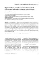
The first sample tree – Tilia_1 was prepared for taking frontal
images of the heat field around the heater. This was achieved by cutting
off the outer segment of the stem (20 cm long) down to the depth of
2.6 cm from the northern stem side (Fig. 1, upper panel). The xylem
surface, opened this way, was then smoothed by a sharp knife and the
IR-camera was focused on the smooth surface. The multi-point HFD
sap flow sensor was installed from the opposite (southern) side of stem,
so that the tip of the long heater reached the smooth surface. The heated
(hot) point visible on the smoothed stem surface occurred at a depth
corresponding to the middle sapwood approximately. The heat field
generated by the linear heater (heated hypodermic needle) was then
simultaneously recorded by the series of multi-point thermometers and
by the IR-camera, which visualized its frontal image (Fig. 1, upper
panel).
The second sample tree – Tilia_2 was prepared to get the radial
image of heat field around the heater (Fig. 1, middle panel). A bigger
part of the stem was cut-off (down to the depth of 4.5 cm from the east-
ern side of the stem) and its surface was smoothed as in the previous
case. The same radial sap flow sensor was installed in the stem, but
in parallel to the smooth stem surface. This way it was made possible
to monitor the radial (parallel to the stem radius) IR-images of the heat
field periodically and to get a continuous record of sap flow at the same
time.
2.2. Sap flow measurements
Sap flow was measured by the heat field deformation (HFD)
method [16, 19]. Sensors consisted of a long linear heater and two pairs
of thermocouples, of which one was placed symmetrically 1.5 cm up
and down from the heater (measured symmetrical temperature difference
dT
sym
), while the other was placed asymmetrically at a short distance
(1.0 cm) on one side of the heater (measured asymmetrical tempera-
ture difference dT
as
) [21]. Reference ends of the thermocouples were
at the same height below the heater. The heater and the thermocouples
were mounted in stainless steel hypodermic needles (always six pairs
of the thermocouples per needle were applied). The ratio of both measured
temperature gradients (dT
sym
/dT
as
), the geometry of the measuring
point and appropriate physical constants were applied for calculation
of the sap flow [19].
2.3. Infra-red imaging
The infrared camera (Model 600 IR Imaging Radiometer from Infr-
ametrics, 1990) with temperature resolution of 0.1
o
C, spectral band-
pass 8–12 micrometer and detector HGCdTe/77 °C was cooled by liq-
uid nitrogen. The camera was mounted on a tripod and focused on the
smoothed xylem surface to take heat field images (Fig. 1, lower panel).
No filters were used, but a silicon teleobjective was applied. Temper-
ature scale was about 4 °C within the range 15 to 22 °C. Several hun-
dreds of IR images were taken periodically. The actual terms of recording
were selected in correspondence with the continuous record of sap flow.
2.4. Cutting experiments
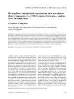
Tilia_1
Tilia_1 was treated in four subsequent steps in order to see in detail
the reaction of the tree, recorded by different techniques from two
opposite sides of the tree stem: (1) First, one main branch of the crown
was cut from two opposite sides approximately until pith (with dis-
tance 25 cm between both cuttings) at 15.38 h (Fig. 2, left) and then
(2) it was removed 11 min after the cutting (Fig. 2, middle). (3) The
main stem was cut below the heater (from the same side, where IR
images were taken) 14 min later after branch removal (Fig. 2, right
scheme and photo). (4) Finally the main stem was cut above the heater
8 min after the first cut from the same side of the stem (Fig. 2, right
scheme and photo).
Tilia_2
In order to get the true zero sap flow in Tilia_2, its main stem was
cut down to the pith 20 cm above the sensor from one side at 15.15 h
and subsequently 10 cm below the sensor from the opposite side of
the stem referring to the radial sensor at 15.38 h (Fig. 1, middle panel).
3. RESULTS AND DISCUSSION
3.1. Heat field around the heater under conditions
of zero-flow
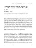
The frontal view of the heat field under zero sap flow appea-
red as a rather symmetrical ellipse, whose axis length in axial
and tangential directions reached the ratio of about 1.3:1, res-
pectively (Fig. 3, upper panel, the first left image) due to dif-
ferent heat conductivities in the corresponding directions.
IR-images taken along the heater installed in radial direction
(reaching from cambium on one side of the stem almost to the
bark on the opposite side) indicated a corresponding heat field,
which approached a symmetrical form (when looking up and
down the heater) under zero sap flow (Fig. 3, lower panel, the
first left image). The clearly distinguishable warm zone around
the heater disappeared gradually (i.e., heat field homogenized
with its surrounding) when heating was switched off. The
disappearing hot point remained on the same place at the heater
axis on the frontal image. Similarly the disappearing warm zone
remained symmetrical along the axis of the heater at the radial
images of the smoothed stem surface (see Fig. 3).
3.2. Heat field around the heater under conditions
of moving sap
3.2.1. Frontal view under switching off
and on the heating
The heat field responded to switching-off the heating by
gradual homogenizing with the surroundings, but it was also
carried upwards by the moving sap (Fig. 4, upper images)
IR images of heat field and sap flow of lime 205
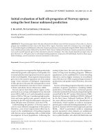
Figure 1. Upper panel (Tilia_1): Schemes and
photo of the lime sample tree stem prepared for
taking infra-red images of heat field around a
linear heater visible in frontal direction: cross-sec-
tion of the tree stem with the radial sap flow sensor
installed from the opposite side of stem and the
infra red camera focused on the smoothed stem
surface. Blue color limits zone with similar flow
rates from both opposite sides of stem (visible by
infra-camera and measured between the second
and third outer thermocouples of the radial sensor).
Two nails were installed on the smoothed surface
of the stem as referent ends: one on the distance of
3 cm apart from the heater and other on the dis-
tance of 3 cm above the first nail. Middle panel
(Tilia_2): Similar schemes and photos of the sam-
ple tree Tilia_2. Radial sap flow sensor was instal-
led in parallel to the smoothed stem surface, so that
the IR-camera “saw” heat field in radial direction.
Scheme of cutting experiments carried out with
Tilia_2 is also shown in the right photo. A nail was
installed on the smoothed surface of the stem as
referent end, marked localization of pith. Yellow
areas in both stem cross-sections correspond to
cut-off parts of stems. Lower panel: General view
of experimental place with sample tree and IR-
equipment.
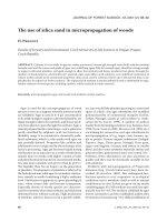
Figure 2. Schemes of complex treatments carried out with Tilia_1, showing
cutting the upper branch (the left panel), removing the upper branch (middle
panel) and cuttings of the stem just above and below of smoothed surface of the
stem, prepared for IR-images (the right panel with photo). The radial sensor was
displaced on the stem below the cut and removed branch. Orange arrows show
distribution of flow, moved through the left part of the stem.
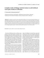
Figure 3. Frontal (upper panel – Tilia_1) and radial (lower panel – Tilia_2) views of
the heat field around the linear heater showing it disappearing from the moments, when
the heater was switched off (upper panel) or removed from the stem (lower panel) in
condition of zero-flow.
206 N. Nadezhdina et al.
together with the hot point originally identical with the heater
axis (Fig. 3, upper images for differences).
On the other hand the same picture illustrates the principle
of the HPV method [9, 10, 14, 24], which is based on recording
the time over which the peak temperature moves across a cer-
tain distance.
Displacement of the hot spot out of its original position vio-
lates one of the main principles of the HFD method (constant
power supply to the heater) and thus sap flow data calculated
after switching off the heating become unrealistic. Similarly it
fits also to heat dissipation method for sap flow measurements
[7], based on simultaneous measurement of heated needle com-
pared to non-heated ones. In practice it is rather difficult some-
times to distinguish short-term non-stable conditions (without
heating), if analyzing only calculated sap flow data (like shown
on Fig. 4, lower panels). In such cases it is very useful also to
analyze records of temperature differences, where continuous
power-supply and moments of its interruptions can be very well
distinguished.
Sap flow could be correctly calculated after 3–5 min of con-
tinuous power supply due to rather quick establishment of tem-
perature gradients around the heater (Fig. 4, lower images) and
especially due to applying their ratio for sap flow calculations.
This is because the point with maximum temperature stays at
the same place (at the axis of the heater) and constantly gene-
rates the heat field. The heat field started to acquire a typical
configuration according to existing sap flow rates just from the
beginning of heating.
3.2.2. Radial view under switching on the heating
IR-images demonstrate radial patterns of flow through the
whole stem section due to application of the long heater.
Various deformation of the heat field in different xylem depths
was recorded by both measuring techniques after switching on
the heater (Fig. 5). Realistic radial patterns of flow can again
be obtained after 3–5 min of continuous heating (Fig. 5, lower
panels). The heat field was no more symmetrical around the
heater axis as under zero flow (Fig. 3, lower images for diffe-
rences), but it was moved upwards by the moving sap, espe-
cially in places with high flow rates. The “hot line” deviated
from the heater axis, especially in the outer sapwood layers,
while little deviation was observed in deeper sapwood (close
to the heartwood): the line remained identical with the heater
axis near the pith. Both measuring techniques also confirmed
certain asymmetry of the treated stem, the left side of which
(where thermocouples of the sensor were placed) was slightly
wider than the right one.
3.3. Cutting experiments
3.3.1. Tilia_2
3.3.1.1. Cutting above the sensor at 15.15 h
(Fig. 1, middle panel)
Heat field responded extremely fast to the destructive treat-
ment, so that its changes in seconds were recorded. The field
started loosing its normal (previously described) form imme-
diately after the cut at the observed stem side and changed it to
an irregular and opposite one representing a downward move-
ment (Fig. 6A). The abrupt decrease of flow till negative values
was simultaneously recorded also by thermocouples of the flow
sensor. Sap flow reached maximum negative values within
3 min after the cut, which were especially pronounced in
sapwood layers, where the flow was higher before (Fig. 6A).
Concerning the measured place at the stem, we must consi-
der the complete change of its pressure situation during its
experimental treatment. The cut represent an abrupt separation
of the sink (foliage) from the source of water (roots/soil). This
caused replacing the usual negative water potential of foliage
by values close to zero (i.e., to the atmospheric pressure) at the
cut surface. Due to this change, roots (holding their original
water potential) started to suck down water from the stem. But
the free stem water storage was very small at the stem segment
between the cut surface and the heater, therefore flow gradually
declined there and finally approached zero. This procedure
down to complete flow cessation in all xylem layers took
13 min (Fig. 6A, lower panels).
It was shown earlier, that integrated sap flow corresponds
to changes in the stem water content before and after the cut
[5]. The water columns in the tree conduits act like an elastic
string being cut apart. The presented results confirm a very simi-
lar situation with simultaneous upward and downward sap
movement, occurring when an aqueous solution under atmos-
pheric pressure was applied into the hole drilled in stems during
staining experiments [6]. However (as it was visible on IR-images),
sap continued to move normally upwards at the opposite (not
damaged) side of the stem at the same time, what indicated tan-
gential stem segmentation.
3.3.1.2. Cutting below the sensor at 15.38 h
(Fig. 1, middle panel)
An increase of flow was recorded by the IR-camera in the
medium sapwood layers within the first minutes this time
(Fig. 6B). A small flow increase was also simultaneously recor-
ded at the opposite stem side, particularly in the inner (xylem)
sapwood layers (close to pith) by the HFD-sensor (Fig. 6B,
lower panels). Concerning the measured place, the cutting now
produced an abrupt separation of the water source from its sink.
This simultaneously released the soil-root resistance and
increased the gradient of water potential between leaves and the
plane of cutting. Also in this case an apparent elastic behavior
of the xylem conduits was observed. The flow slowly approa-
ched zero then (this time in all xylem layers of the whole stem)
again due to limited stem water storage.
3.3.2. Tilia_1
3.3.2.1. Cutting (step 1) and removing (step 2)
the branch above the sensor
(Fig. 2, left and middle panels)
Abrupt decrease of flow in outer xylem layers in the main
stem 5 m below the cut branch within 3 first minutes was recor-
ded by the HFD sensor (Fig. 7, middle upper panel). Then an
increase of flow occurred there in the same layers within the
next 8 min.
IR images of heat field and sap flow of lime 207
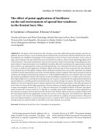
Figure 4. Frontal IR-images of the heat field around
the linear heater in stem of Tilia_1 for periods when
the heater was switched off (upper panel) and swit-
ched on (middle panel) under conditions of moving
sap. Dynamics of sap flow in different xylem depths
as well as temperature differences, recorded by the
HFD-sensor from the opposite side of the stem during
this period and used for calculation of sap flow, are
presented in lower panel. Vertical lines with numbers
mark periods with different sap flow rates, correspon-
ding to IR-images made at time periods: 16
41
, 17
05
,
17
30
and 18
11
. Distances between the heater and two
nails, heated by fingers for reference, are equal to 3 cm
each (see also Fig. 1 for details).
Figure 5. Radial view of IR-images of the heat field around the linear heater in stem of Tilia_2 from the moment, when heating was switched
on. Sap flow dynamics in different xylem depths, recorded by the radial sensor during the same time period, are presented in left lower panel
and radial patterns of flow for periods marked by vertical lines with numbers are presented in right lower panel. Positioning of theoretical (equal
to half of R
xyl
) and real (found after cutting) pith is marked in the last graph too.
208 N. Nadezhdina et al.
Under such conditions some flow apparently still existed
between both partially separated branch parts across 25 cm long
part of the branch still staying in its original position (Fig. 2,
left panel) and part of flow also passed through the measured
part of the stem to the second big upper branch. The radial pat-
tern of flow changed after its following increase: it became
lower in the outer xylem layers but a little higher in inner xylem
layers apparently due to redistribution of flow in xylem. It is
interesting to compare this situation with the branch cut highly
above (around 5 m) the sensor to the cutting experiment on
Tilia_2 with the cut closely above (20 cm) the sensor on the stem.
No flow was recorded by the sensor after cut there (Fig. 6A).
Abrupt reaction on cutting also differed: here some low positive
flow continued after cutting (Fig. 7), while a negative flow
occurred in case of stem cutting just above sensor (Fig. 6A).
No visible change of the heat field was observed by the IR-
camera during this treatment (Fig. 7). Obviously, outer xylem
layers (where we observed the IR-images) were connected pre-
sumably with the second upper branch, which was not damaged.
Gradual decrease of sap flow in outer and middle xylem
layers was observed at the left stem side within the next 12 min
when the cut branch was removed (Fig. 7, lower left panels).
Figure 6. (A) Radial IR-images of the heat field along the linear heater after stem cutting in Tilia_2 above the radial sensor (Fig. 1, middle
panel). Position of the sensor in the stem is shown schematically below IR-image, observed at 15
21
. IR-image, marked by red frame, corres-
ponds to 1 s after cutting. Changing sap flow dynamics in different xylem depths as well as radial patterns corresponded to different time
periods before and after cutting are shown in the left and the right lower panels, respectively. (B) Radial IR-images of heat field around the
linear heater, showing it changing after stem cutting in Tilia_2 below the heater (Fig. 1, middle panel). IR-image, marked by red frame, cor-
responds to moment of cutting. Changing sap flow dynamics in different xylem depths as well as radial patterns corresponded to different time
periods before and after cutting is shown in the left and the right lower panels, respectively.
IR images of heat field and sap flow of lime 209
The flow decreased here mostly in outer xylem layers. The
remaining fraction of flow was obviously related to the flow
moving from roots situated below this side to the second upper
branch. The IR-images showed additional enlargement of heat
field with slightly increasing flow at the side with the IR-
camera, although it was observed during later afternoon. This
could be related with better illumination of the second branch
after removing the first one.
3.3.2.2. Cutting the stem below (step 3) and above (step 4)
the heater from the side, where IR-images were
observed (Fig. 8)
The reaction of the tree, recorded by the sap flow sensor from
the opposite side of the stem, followed rather similar tendency
in both cutting events: the decrease in flow rate was followed
by its gradual increase. The decreases of flow after cuttings may
Figure 7. Scheme of Tilia_1 (middle upper panel) showing cutting of the upper branch, situated above the radial sensor with positioning of the
radial sensor and smoothed surface from the opposite stem side, prepared for IR-images. Orange and yellow arrows show distribution of flow,
moving through each part of the stem to both branches. Scheme of Tilia_1 (middle lower panel) showing removing the upper branch, situated
above the radial sensor. Radial patterns of sap flow and sap flow dynamics in different xylem depths, recorded by the radial profile sensor in
the left stem side, and IR-images of the smoothed surface of the right stem side, recorded by the IR-camera for the same time period before
and after cuttings or branch removing, are presented on the left and the right panels, respectively. Red arrows show periods cutting or removing
the branch.
210 N. Nadezhdina et al.
tentatively be explained as a consequence of redistribution of
tensile forces. The followed increases of flow could be explai-
ned by a decreasing of conducting pathways from side of cut-
ting, drained by the same sink (i.e., leaf area). So, only pathways
from opposite side of stem (where the radial sensor was placed)
can be used after cuttings for water supply to the second branch.
IR-images during these treatments provide information on
the side of stem cutting below the heater: similar as in the case
with Tilia_2 (Fig. 6, upper panel) we also could see a “shock”
of the heat field, caused by severing. The heat field was also
abruptly disturbed here, but by different manner: it became lon-
ger and narrower, especially closely above the heater.
This could correspond to short abrupt increasing of flow due
to sudden release of root-soil resistance and increase of the gra-
dient of water potential between foliage and cut place at the
same time (similar to cutting below the sensor in Tilia_2-
Fig. 6, lower panel).
The following IR-images (Fig. 8) demonstrate that the inner
part of the heat field started to enlarge then and the eccentricity
of the ellipses became smaller, indicating decrease of flow rates
with depletion of the water storage in the remaining part of the
stem. The upper part of the heat field slowly contracted. The
flow stopped completely after the next cutting above the heater.
The heat field continued to enlarge gradually until it reached
the equilibrium (Fig. 8, IR-images). Finally, the form of the
ellipse stabilized, what evidently occurred, when the heat field
became determined by anisotropy (axial to tangential) heat con-
ductivities only (Fig. 8, last right image). This situation occur-
red in contrast to that one, when the sink was deleted abruptly
first (Fig. 6, upper panel: abrupt negative flow was observed).
Responses of flow on abrupt environmental changes, caused by
experimental treatments, as well as presence of flow redistri-
bution in remaining xylem pathways were similar to those, des-
cribed earlier for spruce and lime trees [17, 18].
Summarized pictures of sap flow dynamics and changing
radial patterns of flow during this short (less than 1 h) cutting
experiments are shown in Figure 9, where sap flow dynamics
in different xylem layers is presented in Figure 9A and simpli-
fied schemes of the tree canopy (sink of water) connected
through sapwood of the stem with roots (source of water) are
shown in Figure 9B. Each stem side supplied with water both
opposite parts of the canopy through both opposite sides of the
stem from corresponding water sources. (1) Before the experi-
ments the situation on the opposite sides of the lime stem was
as follows: some flow existed on the left stem side (which was
recorded by the HFD-sensor: radial pattern of flow is shown).
Similar flow took place also on the right side of the stem (where
it was measured by the IR-camera) - (Figs. 9A and 9B, upper
panel). (2) After deleting half of the sink (i.e., one of the two
main branches – see middle panels in Fig. 9B) some pathways
in both stem sides connected to the severed branch were inac-
tivated. Earlier experiments showed, that stem at breast height
is very sectorally connected with source of water (roots), but flow
then spread wider in direction to foliage (Nadezhdina, unpu-
blished). So, any radial cross-section in the stem sapwood is
connected to each big branches, including those from the opposite
side of stem concerning to the considering sector (Nadezhdina,
unpublished). That is why the inactivated pathways were
Figure 8. IR-images of the smoothed surface of the right stem side of Tilia_1 (upper panel) before and after cuttings of the stem (marked by
red arrows with time) below and above the heater from the right stem side (scheme in lower middle panel). Sap flow dynamics (right) as well
as radial patterns of sap flow (left) in different xylem depths, recorded by the radial profile sensor in the left stem side for the same time period
before and after cuttings are presented on the graphs.
IR images of heat field and sap flow of lime 211
present in both stem sides after one branch removing (see mid-
dle panel in Fig. 9B). Flow from the side of the missing sink
decreased significantly especially in outer xylem layers and the
remaining flow moved to the second branch (Figs. 9A and 9B,
middle panel). (3) When only the left stem side functioned par-
tially (see lower panels in Fig. 9B - no flow occurred any more
in the right stem side after its cutting), flow slightly increased
there using the remaining part of water source (roots) towards
the same sink (remaining branch). Magnitude of flow increase
is dependent on water availability in soil in that case. If the IR-
images for all 3 cases discussed above are compared, we can
see two phenomena: first the flow increased after branch remo-
ving (due to better illumination of remaining branch) and then
the flow stopped there completely, after the main stem was cut
(and the heat field come again to equilibrium).
3.4. Analytical characterization of IR heat field pattern
Changes of heat field naturally well corresponded with the
sap flow rates recorded by the HFD sap flow sensors. In general,
behavior of the heat field under different sap flow rates was
similar to that described by other authors [1, 2, 8] and corres-
pond to our previous descriptions, obtained by using series of
thermocouples, arranged around a linear heater [15]. Deforma-
tion of the heat field clearly reflected radial changes in sap flow
[4, 6, 11, 12, 20, 21]. The information obtainable from the infra-
red images of the heat field was analyzed and analytical pro-
cedure was suggested toward improved tools for sap flow
measurement.
Generally, it has to be stated, that reasonably complete
mathematical description of the heat field pattern dynamics in
a xylem structure is too complicated for practical use [3].
However a significant simplification may be possible. Under
conditions of theoretically homogenous material (with equal
heat conductivities in all directions), the heat field pattern
would obtain the form of a circle (Fig. 10, upper panel). Under
real conditions due to asymmetry of heat conductivities, caused
by xylem structure, the iso-temperature profiles in thermogra-
phic pictures around the heated needle are arranged in the form
of ellipses (Fig. 10, upper right scheme and lower left IR-
image). Ratio of heat conductivities, R, in axial and tangential
directions in stems is always higher than 1.The stem xylem is
a complex material consisting mainly of cell-wall solid subs-
tance, water and air. These main fractions of the total xylem
volume V, marked as V
x
, V
w
and V
a
have known heat conduc-
tivities, valid for all woody species (k
xyl_ax
= 0.88; k
xyl_tg
=
0.44; k
wat
= 0.59; k
air
= 0.024 – [23]) and can be easily estima-
ted e.g. on woody cores. Technical literature gives values for
R between 1.6–2.5 for partially dry wood [13, 22]. Estimates
for sapwood in live trees gave lower values of that ratio, from
1.2 to 1.7 for poplar, oak, spruce and pine (Cermak, unpu-
blished).
Under zero-flow the ratio of the axes (a/b) in IR-ellipses
could also provide information on the asymmetry of heat con-
duction parallel and perpendicular to the stem axes. Values,
readable from IR pictures (Fig. 10), confirm the volumetric
estimates.
The ellipses follow the well known mathematical laws: they
are described by two axes – a and b, two focuses F1 and F2
and the center M. The distance from focus F1 via any point P
on the ellipse to focus F2 is equivalent to the twice length of
the main bigger axis. This simply reflects the fact that heat, lea-
ving focus F1 in any direction and at any flow rates, will always
be determined by the second focus F2.
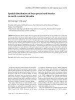
IR-images, shown in Figure 10, demonstrate, how the ellip-
ses of iso-temperature profiles change with increasing sap flow
rates. For zero-flow conditions the heating source is situated in
the center of the ellipse (Fig. 10, left IR-image). When the sap
starts to move, the center M of the ellipse is carried upwards,
because the asymmetric heat conductivity is compensated and
the lower focus F1 gradually approaches the heater (Fig. 10).
Under higher sap flow rates it remains localized there, while
the upper focus F2 and the center of the ellipse M continue to
move upwards with increasing sap flow. At the same time the
b –axis of the ellipse becomes smaller, satisfying the condition
that eccentricity, e, of the ellipse (equal to the half of the dis-
tance between focuses) is increasing simultaneously (Fig. 10:
e’’’ > e’’ > e’). Intuitively one can imagine, that the heat can-
not progress so far away perpendicular to the stem axis, because
it is transported along the stem with the sap. It is well visible
also, that definite zone of sensitivity for measurements exists
around the heater depending on used power supply: isothermal
profiles become bigger and lose their elliptical forms with
increasing distances from the heater. So, some compromise
should be found between applied power and sensor’s geometry.
Considering the mathematical properties of ellipses and adap-
ting the measured IR-patterns of heat fields (particularly the
eccentricity of ellipses) may therefore provide an important
tool for further improving our knowledge on measuring sap
flow rates, when using internal point heating. This strategy will
be adapted in a forthcoming paper.
4. CONCLUSIONS
The selected field experiments on large trees with combined
multi-point thermometer technique (applied in HFD-method)
and IR-imaging technique allowed comparable evaluation of
characteristic thermodynamic features of the heat field around
a linear heater in tree stems under well defined experimental
conditions. Both measurement techniques are invasive for
trees, but to a different extent. Both methods are based on tem-
perature measurements. While the IR-technique gives a full
picture of the heat field distribution around the heater, the HFD
measures only two distinct temperature gradients. The heat
field on IR-images is shown in a wider environment from the
heater, then with point sensor techniques. A special advantage
of the direct IR-visualization of the heat field dynamics is that
the cohesion properties of the xylem water can be intuitively
interpreted and understood. The IR also shows directly the
xylem anisotropy (axial and tangential), which could be quan-
tified and depicted.
However, the IR-method measures the heat field in only one
layer of observation (tangential or radial), while the HFD-tech-
nique can monitor the depth (many layers) simultaneously.
HFD-method allows simultaneous measurements of sap flow
in many compartments of a tree as well, what hardly could be
achieved with IR-technique.
Comparison the HFD-method with IR-technique in situ confir-
med the ability of the HFD for measurements of the bi-directional
212 N. Nadezhdina et al.
Figure 9. (A) Sap flow dynamics in different xylem depths,
recorded by the radial sensor in the left side of the stem during
complex treatments carried out with Tilia_1. Four vertical lines
with arrow correspond to period of different treatments marked
above them (see also Figs. 7 and 8). (B) Simplified schemes
of complex treatments carried out with Tilia_1 (Figs. 2, 7, 8
and 9A), showing tree before treatments (upper panels), after
removing one upper (left) branch (middle panels) and cuttings
of the right side of the stem (lower panels). All these three
periods marked by vertical line with numbers on graph with sap
flow dynamics (Fig. 9A). Parts of stem not filled by color pre-
sent inactivated xylem vessels in both sides of the stem. Radial
patterns, recorded by the radial sensor for chosen periods of the
experiment are shown in the left side and IR-images of smoo-
thed surface of the stem for the same moments – in the right
side. IR-images represented only one measured point along
stem radius- that one with maximum flow at the smoothed stem
surface.
Figure 10. Theoretical schemes of a heat field in the stem
xylem around a linear heater under zero-flow conditions (upper
panel): it is a circle (left) under ideal conditions with equal heat
conductivities in axial (K_ax) and tangential (K_tg) directions
and an ellipse (right) in reality due to asymmetry in heat con-
ductivities (K_ax > K_tg) in tree stem. M – center of a circle
or an ellipse, F1, F2 – focuses of an ellipse, a and b – main axes
of an ellipse, e – eccentricity of an ellipse. IR-images of the heat
field (lower panel) under zero-flow (left) and with increasing
sap flow rates (middle and right images, respectively): numbers
of inverted commas nearby letters mark situation with different
increasing sap flow rates, starting from zero. Red horizontal
line marks the axis of the heater. Scale: small axis (b1) of one
of the ellipses under zero flow (drawn by white color in the left
IR-image) is equal to 1 cm.
IR images of heat field and sap flow of lime 213
and extremely low flows (those approaching zero, such as re-
saturating flows at night). Fast responding and high sensitivity
of the HFD-method to any changes within xylem pathways,
demonstrated during severing experiments, also showed its
capability for studies of tree architecture and function, inclu-
ding flow redistribution within trees.
Visualization of the heat field also allows evaluation of opti-
mal positioning of the sap flow sensors. For this purpose the
mathematical properties of the dynamics of heat field (via ellip-
ses with different eccentricities) will have to be evaluated and
the sensor geometry could be optimized in order to measure the
relevant parameters.
Acknowledgements: This study was done within the project of
Hahn-Meither Institute and analysed within the framework of
WATERUSE project (EVK1-CT-2000-00079).
REFERENCES
[1] Anfodillo T., Sabatti M., Sigalotti G.B., Valentini R., An application
of infrared thermal image to monitor water transport in plants, in:
Carlomagno G.M., Corso C. (Eds.), Advanced Infrared Technology
and Applications, Firenze, 1992, pp. 427–437.
[2] Anfodillo T., Sigalotti G.B., Tomasi M., Semenzato P., Valentini R.,
Application of thermal imaging in the study of sap flow in woody
species. Plant Cell Environ. 16 (1993) 997–1001.
[3] Carslaw H.S., Jaeger J.C., Heat in Solids, Oxford University (Clare-
don) Press, 2nd Issue, 1962.
[4] ermák J., Nadezhdina N., Sapwood as the scaling parameter - defi-
ning according to xylem water content or radial pattern of flow? Ann.
Sci. For. 55 (1998) 509–521.
[5] ermák J., Jeník J., Ku era J., Zidek V., Xylem water flow in a crack
willow tree (Salix fragilis L.) in relation to diurnal changes of envi-
ronment, Oecologia 64 (1984) 145–151.
[6] ermák J., Cienciala E., Ku era J., Lindroth A., Hallgren J.E., Radial
velocity profiles of water flow in stems of spruce and oak and res-
ponse of spruce tree to severing, Tree Physiol. 10 (1992) 367–380.
[7] Granier A., A new method to measure the raw sap flux in the trunk
of trees, Ann. Sci. For. 42 (1985) 193–200.
[8] Granier A., Anfodillo T., Sabatti M., Cochard H., Dreyer E., Tomasi
M., Valentini R., Breda N., Axial and radial water flow in the trunks
of oak trees: a quantitative and qualitative analysis, Tree Physiol. 14
(1994) 1383–1396.
[9] Huber B., Weitere quantitative Untersuchungen uber das Wasser-
leitungssystem der pflanzen, Jahrsblad des wissenschaftliche
Botany 67 (1936) 877–959.
[10] Huber B., Schmidt E., Weitere thermoelektrische Untersuchungen
uber den Transpirationsstrom der Baume, Tharandter Forstliche
Jahrsblad 87 (1936) 369–412.
[11] Jimenez M.S., Nadezhdina N., ermák J., Morales D., Radial varia-
tion in sap flow rate in five laurel forest tree species in Tenerife,
Canary Islands, Tree Physiol. 20 (2000) 1149-1156.
[12] Lambs L., Muller E., Sap flow and water transfer in the Garrone
River riparian woodland, France: first results on poplar and willow,
Ann. For. Sci. 59 (2002) 301–315.
[13] MacLean J.D., Thermal Conductivity of Wood, Heating, Piping, and
Air Conditioning 13 (1941) 380–391.
[14] Marshall D.C., Measurements of sap flow in conifers by heat trans-
port, Plant Physiol. 33 (1958) 385–396.
[15] Nadezhdina N., Temperature gradients around a linear heater in
stems due to mowing sap, in: Cermak J., Nadezhdina N. (Eds.),
Measuring Sap Flow in Intact Plants, Proc. of 4th. Int. Workshop,
Zidlochovice, Czech Republic, IUFRO Publications, Brno, Czech
Republic, Publishing House of Mendel University, 1998, pp. 65–71.
[16] Nadezhdina N., ermák J., The technique and instrumentation for
estimation the sap flow rate in plants (in Czech), Patent No. 286438
(PV-1587-98), 1998.
[17] Nadezhdina N., ermák J., Responses of Sap flow rate along tree
stem and coarse root radii to changes of water supply, in: Stokes A.
(Ed.), The Supporting Roots of Trees and Woody Plants: Form,
Function and Physiology. Developments in Plant and Soil Sciences,
Vol. 87, Kluwer Academic Publishers, 2000, pp. 227–238.
[18] Nadezhdina N., ermák J., Responses of sap flow in spruce roots to
mechanical injury, in: Klimo E., Hager H., Kulhavy J. (Eds.), Spruce
Monocultures in Central Europe: Problems and Prospects, EFI Proc.
No. 33, 2000, pp. 167–175.
[19] Nadezhdina N., ermák J., Nadezhdin V., Heat field deformation
method for sap flow measurements, in: ermák J., Nadezhdina N.
(Eds.), Measuring Sap Flow in Intact Plants, Proc. of 4th. Int. Works-
hop, Zidlochovice, Czech Republic, IUFRO Publications, Brno,
Czech Republic, Publishing House of Mendel University, 1998,
pp. 72–92.
[20] Nadezhdina N., ermák J., Morales D., Jimenez M.S., Raschi A.,
Tognetti R., Ferreira M.J., Variations in conducting patterns of trees
growing in three Mediterranean countries and relations to crown
development, in: Radoglu K. (Ed.), Forest Research: a Challenge for
an Integrated European Approach, Proc. of the Int. Conf., Thessa-
loniki, Greece, 2001, pp. 507–512.
[21] Nadezhdina N., ermák J., Ceulemans R., Radial patterns of sap
flow in woody stems of dominant and understory species: scaling
errors associated with positioning of sensors, Tree Physiol. 22
(2002) 907–918.
[22] Perelygin L.M., Ugolev B.N., Woodscience (in Russian), Lesnaja
Promyschlennost, Moskva, 1971.
[23] Siau J.F., Wood: Influence of Moisture on Physical Properties, Vir-
ginia Polytechnic Institute and State University, 1995.
[24] Swanson R.H., Numerical and experimental analysis of implanted-
probe heat-pulse theory, Ph.D. thesis, University Alberta, Canada,
1983.
C
v
C
v
c
v
C
v
c
v
C
v
C
v
C
v
C
v
C
v
C
v
C
v
C
v