SystemVerilog For Design phần 7 pdf
Bạn đang xem bản rút gọn của tài liệu. Xem và tải ngay bản đầy đủ của tài liệu tại đây (223.69 KB, 40 trang )
236 SystemVerilog for Design
.reg_file_sel(reg_file_sel),
.zero_enable(zero_enable),
.carry_enable(carry_enable),
.polarity(polarity),
.option(isoption),
.tris(istris),
.instruct_reg(instruct_reg)
);
register_files regs (
.dout(reg_file_out),
.tmr0_reg(tmr0_reg),
.status_reg(status_reg),
.fsr_reg(fsr_reg),
.port_a(port_a),
.port_b(port_b),
.port_c(port_c),
.trisa(trisa),
.trisb(trisb),
.trisc(trisc),
.option_reg(option_reg),
.w_reg(w_reg),
.instruct_reg(instruct_reg),
.program_data(program_data),
.port_a_pins(port_a_pins),
.data_bus(data_bus),
.address(reg_file_addr),
.clk(clk),
.resetN(resetN),
.skip(skip),
.reg_file_sel(reg_file_sel),
.zero_enable(zero_enable),
.carry_enable(carry_enable),
.w_reg_enable(w_reg_enable),
.reg_file_enable(reg_file_enable),
.zero(zero),
.carry(carry),
.special_reg_sel(special_reg_sel),
.isoption(isoption),
.istris(istris)
);
alu alu (
.y(data_bus),
.carry_out(carry),
.zero_out(zero),
.a(alu_a),
.b(alu_b),
Chapter 9: SystemVerilog Design Hierarchy 237
.opcode(alu_opcode),
.carry_in(status_reg[0])
);
glue_logic glue (
.port_b_pins(port_b_pins),
.port_c_pins(port_c_pins),
.alu_a(alu_a),
.alu_b(alu_b),
.expan_out(expan_out),
.expan_addr(expan_addr),
.reg_file_addr(reg_file_addr),
.reg_file_enable(reg_file_enable),
.special_reg_sel(special_reg_sel),
.expan_read(expan_read),
.expan_write(expan_write),
.skip(skip),
.instruct_reg(instruct_reg),
.program_counter(program_counter),
.port_a(port_a),
.port_b(port_b),
.port_c(port_c),
.data_bus(data_bus),
.expan_in(expan_in),
.fsr_reg(fsr_reg),
.tmr0_reg(tmr0_reg),
.status_reg(status_reg),
.w_reg(w_reg),
.reg_file_out(reg_file_out),
.alu_a_sel(alu_a_sel),
.alu_b_sel(alu_b_sel),
.reg_file_sel(reg_file_sel),
.polarity(polarity),
.zero(zero)
);
endmodule
Named port connection advantages
An advantage of named port connections is that they reduce the risk
of an inadvertent design error because a net was connected to the
wrong port. In addition, the named port connections better docu-
ment the intent of the design. In the example above, it is very obvi-
ous which signal is intended to be connected to which port of the
name
d
por
t
connections are
a preferred style
238 SystemVerilog for Design
flip-flop, without having to go look at the source code of each mod-
ule. Many companies have internal modeling guidelines that
require using the named port connection style in netlists, because of
these advantages.
Named port connection disadvantages
The disadvantage of the named port connection style is that it is
very verbose. Netlists can contain tens or hundreds of module
instances, and each instance can have dozens of ports. Both the
name of the port and the name of the net connected to the port must
be listed for each and every port connection in the netlist. Port and
net names can be up to 1024 characters long in Verilog tools. When
long, descriptive port names and net names are used, and there are
many ports for each module name, the size and verbosity of a netlist
using named port connections can become excessively large and
difficult to maintain.
9.4.1 Implicit .name port connections
SystemVerilog provides three enhancements that greatly simplify
netlists:
.name (pronounced “dot-name”) port connections, .*
(pronounced “dot-star”) port connections, and interfaces. The
.name and .* styles are discussed in the following subsections,
and interfaces are presented in Chapter 10.
The SystemVerilog
.name port connection syntax combines the
advantages of both the conciseness of ordered port connections
with self-documenting code and order independence of named-port
connections, eliminating the disadvantages of each of the two Ver-
ilog styles. In many Verilog netlists, especially top-level netlists
that connect major design blocks together, it is common to use the
same name for both the port name and the name of the net con-
nected to the port. For example, the module might have a port
called
data, and the interconnected net is also called data.
Using Verilog’s named port connection style, it is necessary to
repeat the name twice in order to connect the net to the port, for
example:
.data(data). SystemVerilog simplifies the named port
connection syntax by allowing just the port name to be specified.
When only the port name is given, SystemVerilog infers that a net
or variable of the same name will automatically be connected to the
name
d
por
t
connections are
verbose
.name
i
s an
abbreviation of
named port
connections
.name s
i
mp
lifi
es
connections to
module
instances
.name
i
n
f
ers a
connection of a
net and port of
the same name
Chapter 9: SystemVerilog Design Hierarchy 239
port. This means the verbose Verilog style of .data(data) can be
reduced to simply
.data.
When the name of a net does not match the port to which it is to be
connected, the Verilog named port connection is used to explicitly
connect the net to the port. As with the Verilog named port connec-
tions, an unconnected port can be left either unspecified, or explic-
itly named with an empty parentheses set to show that there is no
connection.
Example 9-4 lists the simple processor model shown previously in
example 9-3, but with SystemVerilog’s
.name port connection
style for all nets that are the same name as the port. Compare this
example to example 9-3, to see how the
.name syntax reduces the
verbosity of named port connections. Using the
.name connection
style, the netlist is easier to read and to maintain.
Example 9-4: Simple netlist using SystemVerilog’s .name port connections
module miniPIC (
inout wire [7:0] port_a_pins,
inout wire [7:0] port_b_pins,
inout wire [7:0] port_c_pins,
input wire clk,
input wire resetN
);
wire [11:0] instruct_reg, program_data;
wire [10:0] program_counter, program_address;
wire [ 7:0] tmr0_reg, status_reg, fsr_reg, w_reg, option_reg,
reg_file_out, port_a, port_b, port_c, trisa,
trisb, trisc, data_bus, alu_a, alu_b;
wire [ 6:0] reg_file_addr;
wire [ 3:0] alu_opcode;
wire [ 1:0] alu_a_sel, alu_b_sel;
wire reg_file_sel, special_reg_sel, reg_file_enable,
w_reg_enable, zero_enable, carry_enable, skip,
isoption, istris, polarity, carry, zero;
pc_stack pcs ( // module instance with .name port connections
.program_counter,
.program_address,
.clk,
.resetN,
.instruct_reg,
.data_bus,
.name can
b
e
combined with
named port
connections
240 SystemVerilog for Design
.status_reg
);
prom prom (
.dout(program_data),
.clk,
.address(program_address)
);
instruction_decode decoder (
.alu_opcode,
.alu_a_sel,
.alu_b_sel,
.w_reg_enable,
.reg_file_sel,
.zero_enable,
.carry_enable,
.polarity,
.option(isoption),
.tris(istris),
.instruct_reg
);
register_files regs (
.dout(reg_file_out),
.tmr0_reg,
.status_reg,
.fsr_reg,
.port_a,
.port_b,
.port_c,
.trisa,
.trisb,
.trisc,
.option_reg,
.w_reg,
.instruct_reg,
.program_data,
.port_a_pins,
.data_bus,
.address(reg_file_addr),
.clk,
.resetN,
.skip,
.reg_file_sel,
.zero_enable,
.carry_enable,
.w_reg_enable,
Chapter 9: SystemVerilog Design Hierarchy 241
.reg_file_enable,
.zero,
.carry,
.special_reg_sel,
.isoption,
.istris
);
alu alu (
.y(data_bus),
.carry_out(carry),
.zero_out(zero),
.a(alu_a),
.b(alu_b),
.opcode(alu_opcode),
.carry_in(status_reg[0])
);
glue_logic glue (
.port_b_pins,
.port_c_pins,
.alu_a,
.alu_b,
.reg_file_addr,
.reg_file_enable,
.special_reg_sel,
.skip,
.instruct_reg,
.program_counter,
.port_a,
.port_b,
.port_c,
.data_bus,
.fsr_reg,
.tmr0_reg,
.status_reg,
.w_reg,
.reg_file_out,
.alu_a_sel,
.alu_b_sel,
.reg_file_sel,
.polarity,
.zero
);
endmodule
242 SystemVerilog for Design
In order to infer a connection to a named port, the net or variable
must match both the port name and the port vector size. In addition,
the types on each side of the port must be compatible. Incompatible
types are any port connections that would result in a warning or
error if a net or variable is explicitly connected to the port. The
rules for what connections will result in errors or warnings are
defined in the IEEE 1364-2005 Verilog standard, in section
12.3.10
1
. For example, a tri1 pullup net connected to a tri0 pull-
down net through a module port will result in a warning, per the
Verilog standard. Such a connection will not be inferred by
the
.name syntax.
These restrictions reduce the risk of unintentional connections
being inferred by the
.name connection style. Any mismatch in
vector sizes and/or types can still be forced, using the full named
port connection style, if that is the intent of the designer. Such mis-
matches must be explicitly specified, however. They will not be
inferred from the
.name syntax.
9.4.2 Implicit .* port connection
SystemVerilog provides an additional short cut to simplify the spec-
ification of large netlists. The
.* syntax indicates that all ports and
nets (or variables) of the same name should automatically be con-
nected together for that module instance. As with the
.name syn-
tax, for a connection to be inferred, the name and vector size must
match exactly, and the types connected together must be compati-
ble. Any connections that cannot be inferred by
.* must be
explicitly connected together, using Verilog’s named port connec-
tion syntax.
Example 9-5 illustrates the use of SystemVerilog’s
.* port con-
nection syntax.
1. IEEE Std 1364-2005, Language Reference Manual (LRM). See page xxvii of this book for
details.
.name
connection
inference rules
.
*i
n
f
ers
connections of
all nets and
ports of the
same name
Chapter 9: SystemVerilog Design Hierarchy 243
Example 9-5: Simple netlist using SystemVerilog’s .* port connections
module miniPIC (
inout wire [7:0] port_a_pins,
inout wire [7:0] port_b_pins,
inout wire [7:0] port_c_pins,
input wire clk,
input wire resetN
);
wire [11:0] instruct_reg, program_data;
wire [10:0] program_counter, program_address;
wire [ 7:0] tmr0_reg, status_reg, fsr_reg, w_reg, option_reg,
reg_file_out, port_a, port_b, port_c, trisa,
trisb, trisc, data_bus, alu_a, alu_b;
wire [ 6:0] reg_file_addr;
wire [ 3:0] alu_opcode;
wire [ 1:0] alu_a_sel, alu_b_sel;
wire reg_file_sel, special_reg_sel, reg_file_enable,
w_reg_enable, zero_enable, carry_enable, skip,
isoption, istris, polarity, carry, zero;
pc_stack pcs ( // module instance with .* port connections
.*
);
prom prom (
.*,
.dout(program_data),
.address(program_address)
);
instruction_decode decoder (
.*,
.option(isoption),
.tris(istris)
);
register_files regs (
.*,
.dout(reg_file_out),
.address(reg_file_addr)
);
alu alu (
.y(data_bus),
.carry_out(carry),
.zero_out(zero),
.a(alu_a),
244 SystemVerilog for Design
.b(alu_b),
.opcode(alu_opcode),
.carry_in(status_reg[0])
);
glue_logic glue (
.*
);
endmodule
9.5 Net aliasing
SystemVerilog adds an alias statement that allows two different
names to reference the same net. For example:
wire clock;
wire clk;
alias clk = clock;
The net clk is an alias for clock, and clock is an alias for clk.
Both names refer to the same logical net.
Defining an alias for a net does not copy the value of one net to
some other net. In the preceding example,
clk is not a copy of
clock. Rather, clk is clock, just referenced by a different name.
Any value changes on
clock will be seen by clk, since they are
the same net. Conversely, any value changes on
clk will be seen by
clock, since they are the same net.
SystemVerilog adds two new types of hierarchy blocks that can
also have ports, interfaces (see Chapter 10), and programs (refe
r
to the companion book, SystemVerilog for Verification).
Instances of these new blocks can also use the .name and .*
inferred port connections. SystemVerilog also allows calls to
functions and tasks to use named connections, including the
.name and .* shortcuts. This is covered in section 6.3.5 on
page 156.
NOTE
an a
li
as crea
t
es
two or more
names for the
same net
Chapter 9: SystemVerilog Design Hierarchy 245
alias versus assign
The alias statement is not the same as the assign continuous
assignment. An
assign statement continuously copies an expres-
sion on the right-hand side of the assignment to a net or variable on
the left-hand side. This is a one-way copy. The net or variable on
the left-hand side reflects any changes to the expression on the
right-hand side. But, if the value of the net or variable on the left-
hand side is changed, the change is not reflected back to the expres-
sion on the right-hand side.
An
alias works both ways, instead of one way. Any value changes
to the net name on either side of the alias statement will be reflected
on the net name on the other side. This is because an alias is effec-
tively one net with two different names.
Multiple aliases
Several nets can be aliased together. A change on any of the net
names will be reflected on all of the nets that are aliased together.
wire reset, rst, resetN, rstN;
alias rst = reset;
alias reset = resetN;
alias resetN = rstN;
The previous set of aliases can also be abbreviated to a single state-
ment containing a series of aliases, as follows:
alias rst = reset = resetN = rstN;
The order in which nets are listed in an alias statement does not
matter. An alias is not an assignment of values, it is a list of net
names that refer to the same object.
9.5.1 Alias rules
SystemVerilog imposes several restrictions on what signals can be
aliased to another name.
• Only the net types can be aliased. Variables cannot be aliased.
Verilog’s net types are
wire, uwire, wand, wor, tri, triand,
trior, tri0, tri1, and trireg.
an a
li
as
i
s no
t
an assignment
c
h
anges on any
aliased net
affect all aliased
nets
a
li
ases are no
t
order dependent
on
l
y ne
tt
ypes
can be aliased
246 SystemVerilog for Design
• The aliased net type must be the same net type as the net to which
it is aliased. A
wire type can be aliased to a wire type, and a
wand type can be aliased to a wand type. It is an error, however,
to alias a
wire to a wand or any other type.
• The aliased net and the net to which it is aliased must be the same
vector size. Note, however, that bit and part selects of nets can be
aliased, so long as the vector size of the left-hand side and right-
hand side of the alias statement are the same.
The following examples are all legal aliases of one net to another:
wire [31:0] n1;
wire [3:0][7:0] n2;
alias n2 = n1; // both n1 and n2 are 32 bits
wire [39:0] d_in;
wire [7:0] crc;
wire [31:0] data;
alias data = d_in[31:0]; // 32 bit nets
alias crc = d_in[39:32]; // 8 bit nets
9.5.2 Implicit net declarations
An alias statement can infer net declarations. It is not necessary to
first explicitly declare each of the nets in the alias. Implicit nets are
inferred, following the same rules as in Verilog for inferring an
implicit net when an undeclared identifier is connected to a port of
a module or primitive instance. In brief, these rules are:
• An undeclared identifier name on either side of an alias statement
will infer a net type.
• The default implicit net type is
wire. This can be changed with
the
‘default_nettype compiler directive.
• If the net name is listed as a port of the containing module, the
implicit net will be the same vector size as the port.
• If the net name is not listed in the containing module’s port list,
then a 1-bit net is inferred.
The following example infers single bit nets called
reset and
rstN, and 64 bit nets called q and d:
on
l
y ne
t
s o
fth
e
same type can
be aliased
on
l
y ne
t
s o
fth
e
same size can
be aliased
i
mp
li
c
it
ne
t
s can
be inferred from
an alias
Chapter 9: SystemVerilog Design Hierarchy 247
module register (output [63:0] q,
input [63:0] d,
input clock, reset);
wire [63:0] out, in;
alias in = d; // infers d is a 64-bit wire
alias out = q; // infers q is a 64-bit wire
alias rstN = reset; // infers 1-bit wires
Net aliasing can also be used to define a net that represents part of
another net. In the following example,
lo_byte is an alias for the
lower byte of a vector, and
hi_byte is an alias for the upper byte.
Observe that the order of signals in the alias statement does not
matter. An alias is not an assignment statement. An alias is just
multiple names for the same physical wires.
module ( );
wire [63:0] data;
wire [7:0] lo_byte, hi_byte;
alias data[7:0] = lo_byte;
alias hi_byte = data[63:56];
endmodule
9.5.3 Using aliases with .name and .*
The alias statement enables greater usage of the .name and .*
shortcuts for modeling netlists. These shortcuts are used to connect
a module port and net of the same name together, without the ver-
bosity of Verilog’s named port connection syntax. In the following
example, however, these shortcuts cannot be fully utilized to con-
nect the clock signals together, because the port names are not the
same in each of the modules.
248 SystemVerilog for Design
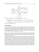
Figure 9-1: Diagram of a simple netlist
Example 9-6: Netlist using SystemVerilog’s .* port connections without aliases
module chip (input wire master_clock,
input wire master_reset,
);
wire [31:0] address, new_address, next_address;
ROM i1 ( .*, // infers .address(address)
.data(new_address),
.clk(master_clock) );
program_count i2 ( .*, // infers .next_address(next_address)
.jump_address(new_address),
.clock(master_clock),
.reset_n(master_reset) );
address_reg i3 ( .*, // no connections can be inferred
.next_addr(next_address),
.current_addr(address),
.clk(master_clock),
.rstN(master_reset) );
endmodule
module ROM (output wire [31:0] data,
input wire [31:0] address,
input wire clk);
endmodule
ROM program address
count reg
data
address
clk
next_addr
clock
jump_address
reset_n
clk
rstN
current_addr
next_address
master_clock
master_reset
new_address
next_address
address
Chapter 9: SystemVerilog Design Hierarchy 249
module program_count (output logic [31:0] next_address,
input wire [31:0] jump_address,
input wire clock, reset_n);
endmodule
module address_reg (output wire [31:0] current_addr,
input wire [31:0] next_addr,
input wire clk, rstN);
endmodule
The master_clock in chip should be connected to all three mod-
ules in the netlist. However, the clock input ports in the modules are
not called
master_clock. In order for the master_clock net in
the top-level
chip module to be connected to the clock ports of the
other modules, all of the different clock port names must be aliased
to
master_clock. Similar aliases can be used to connect all reset
ports to the
master_reset net, and to connect other ports together
that do not have the same name.
Example 9-7 adds these alias statements, which allow the netlist to
take full advantage of the
.* shortcut to connect all modules
together. In this example, wires for the vectors are explicitly
declared, and wires for the different clock and reset names are
implicitly declared from the alias statement.
Example 9-7: Netlist using SystemVerilog’s .* connections along with net aliases
module chip (input wire master_clock,
input wire master_reset,
);
wire [31:0] address, data, new_address, jump_address,
next_address, next_addr, current_addr;
alias clk = clock = master_clock;
alias rstN = reset_n = master_reset;
alias data = new_address = jump_address;
alias next_address = next_addr;
alias current_addr = address;
ROM i1 ( .* );
us
i
ng a
li
ases
can simplify
netlists
250 SystemVerilog for Design
program_count i2 ( .* );
address_reg i3 ( .* );
endmodule
module ROM (output wire [31:0] data,
input wire [31:0] address,
input wire clk);
endmodule
module program_count (output logic [31:0] next_address,
input wire [31:0] new_count,
input wire clock, reset_n);
endmodule
module address_reg (output wire [31:0] address,
input wire [31:0] next_address,
input wire clk, rstN);
endmodule
In this example, the .* shortcuts infer the following connections to
the module ports of the module instances:
ROM i1 (.data(data),
.address(address)
.clk(clk) );
program_count i2 (.next_address(next_address),
.jump_address(jump_address),
.clock(clock),
.reset_n(reset_n) );
address_reg i3 (.current_addr(current_addr),
.next_addr(next_addr),
.clk(clk),
.rstN(rstN) );
Even though different net names are connected to different module
instances, such as
clk to the ROM module and clock to the
program_count module, the alias statements make them the same
net, and make those nets the same as
master_clock.
Chapter 9: SystemVerilog Design Hierarchy 251
9.6 Passing values through module ports
The Verilog language places a number of restrictions on what types
of values can be passed through the ports of a module. These
restrictions affect both the definition of the module and any
instances of the module. The following bullets give a brief sum-
mary of the Verilog restrictions on module ports:
• Only net types, such as the
wire type, can be used on the receiv-
ing side of the port. It is illegal to connect any type of variable,
such as
reg or integer , to the receiving side of a module port.
• Only net,
reg, and integer types, or a literal integer value can
be used on the transmitting side of the port.
• It is illegal to pass the
real type through module ports without
first converting it to a vector using the
$realtobits system
function, and then converting it back to a real number, after pass-
ing through the port, with the
$bitstoreal system function.
• It is illegal to pass unpacked arrays of any number of dimensions
through module ports.
9.6.1 All types can be passed through ports
SystemVerilog removes nearly all restrictions on the types of values
that can be passed through module ports. With SystemVerilog:
• Values of any type can be used on both the receiving and trans-
mitting sides of module ports, including real values.
• Packed and unpacked arrays of any number of dimensions can be
passed through ports.
• SystemVerilog structures and unions can be passed through mod-
ule ports.
The following example illustrates the flexibility of passing values
through module ports in SystemVerilog. In this example, variables
are used on both sides of some ports, a structure is passed through a
V
er
il
og
restrictions on
module ports
S
ys
t
em
V
er
il
og
removes most
port restrictions
SystemVerilog adds two new types of hierarchy blocks that can
also have ports, interfaces (see Chapter 10), and programs (refer
to the companion book, SystemVerilog for Verification). These
new blocks have the same port connection rules as modules.
NOTE
252 SystemVerilog for Design
port, and an array, representing a look-up table, is passed through a
port.
Example 9-8: Passing structures and arrays through module ports
typedef struct packed {
logic [ 3:0] opcode;
logic [15:0] operand;
} instruction_t;
module decoder (output logic [23:0] microcode,
input instruction_t instruction,
input logic [23:0] LUT [0:(2**20)-1] );
// do something with Look-Up-Table and instruction
endmodule
module DSP (input logic clock, resetN,
input logic [ 3:0] opcode,
input logic [15:0] operand,
output logic [23:0] data );
logic [23:0] LUT [0:(2**20)-1]; // Look Up Table
instruction_t instruction;
logic [23:0] microcode;
decoder i1 (microcode, instruction, LUT);
// do something with microcode output from decoder
endmodule
9.6.2 Module port restrictions in SystemVerilog
SystemVerilog does place two restrictions on the values that are
passed through module ports. These restrictions are intuitive, and
help ensure that the module ports accurately represent the behavior
of hardware.
The first restriction is that a variable type can only have a single
source that writes a value to the variable at any given moment in
time. A source can be:
var
i
a
bl
es can
only receive
values from a
single source
Chapter 9: SystemVerilog Design Hierarchy 253
• a single module output or inout port
• a single primitive output or inout port
• a single continuous assignment
• any number of procedural assignments
The reason for this single source restriction when writing to vari-
ables is that variables simply store the last value written into them.
If there were multiple sources, the variable would only reflect the
value of the last source to change. Actual hardware behavior for
multi-source logic is different. In hardware, multiple sources, or
“drivers”, are merged together, based on the hardware technology.
Some technologies merge values based on the strength of the driv-
ers, some technologies logically-and multiple drivers together, and
others logically-or multiple drivers together. This implementation
detail of hardware behavior is represented with Verilog net types,
such as
wire, wand, and wor. Therefore, SystemVerilog requires
that a net type be used when a signal has multiple drivers. An error
will occur if a variable is connected to two drivers.
Any number of procedural assignments is still considered a single
source for writing to the variable. This is because procedural
assignments are momentary statements that store a value but do not
continuously update that value. For example, in an
if else pro-
graming statement, either one branch or the other can be used to
update the value of the same variable, but both branches do not
write to the same variable at the same time. Even multiple proce-
dural assignments to the same variable at the same simulation time
behave as temporary writes to the variable, with the last assignment
executed representing the value that is actually stored in the vari-
able. A continuous assignment or a connection to an output or inout
port, on the other hand, needs to continuously update the variable to
reflect the hardware behavior of a continuous electrical source.
The second restriction SystemVerilog places on values passed
through module ports is that unpacked types must be identical in
layout on both sides of a module port. SystemVerilog allows struc-
tures, unions, and arrays to be specified as either packed or
unpacked (see sections 5.1.3 on page 101, 5.2.1 on page 106, and
5.3.1 on page 113, respectively). When arrays, structures or unions
are unpacked, the connections must match exactly on each side of
the port.
mu
lti
source
logic requires
net types
unpac
k
e
d
values must
have matching
layouts
254 SystemVerilog for Design
For unpacked arrays, an exact match on each side of the port is
when there are the same number of dimensions in the array, each
dimension is the same size, and each element of the array is the
same size.
For unpacked structures and unions, an exact match on each side of
the port means that each side is declared using the same typedef
definition. In the following example, the structure connection to the
output port of the buffer is illegal. Even though the port and the
connection to it are both declared as structures, and the structures
have the same declarations within, the two structures are not
declared from the same user-defined type, and therefore are not an
exact match. The two structures cannot be connected through a
module port. In this same example, however, the structure passed
through the input port is legal. Both the port and the structure con-
nected to it are declared using the same user-defined type defini-
tion. These two structures are exactly the same.
typedef struct { // unpacked structure
logic [23:0] short_word;
logic [63:0] long_word;
} data_t;
module buffer (input data_t in,
output data_t out);
endmodule
module chip ( );
data_t din; // unpacked structure
struct { // unpacked structure
logic [23:0] short_word;
logic [63:0] long_word;
} dout;
buffer i1 (.in(din), // legal connection
.out(dout) // illegal connection
);
endmodule
Packed and unpacked arrays, structures, and unions are discussed in
more detail in Chapter 5.
Chapter 9: SystemVerilog Design Hierarchy 255
The restrictions described above on passing unpacked values
through ports do not apply to packed values. Packed values are
stored as contiguous bits, are analogous to a vector of bits, and are
passed through module ports as vectors. If the array, structure, or
union are different sizes on each side of the port, Verilog’s standard
rules are followed for a mismatch in vector sizes.
9.7 Reference ports
Verilog modules can have input, output and bidirectional inout
ports. These port types are used to pass a value of a net or variable
from one module instance to another.
SystemVerilog adds a fourth port type, called a
ref port. A ref
port passes a hierarchical reference to a variable through a port,
instead of passing the value of the variable. The name of the port
becomes an alias to hierarchical reference. Any references to that
port name directly reference the actual source.
A reference to a variable of any type can be passed through a ref
port. This includes all built-in variable types, structures, unions,
enumerated types, and other user-defined types. To pass a reference
to a variable through a port, the port direction is declared as
ref,
instead of an
input, output, or inout. The type of a ref port
must be the same type as the variable connected to the port.
The following example passes a reference to an array into a mod-
ule, using a
ref port.
Example 9-9: Passing a reference to an array through a module ref port
typedef struct packed {
logic [ 3:0] opcode;
logic [15:0] operand;
} instruction_t;
module decoder (output logic [23:0] microcode,
input instruction_t instruction,
ref logic [23:0] LUT [0:(2**20)-1] );
// do something with Look-Up-Table and instruction
endmodule
pac
k
e
d
va
l
ues
are passed
through ports as
vectors
a re
f
por
t
passes
a hierarchical
reference
through a port
256 SystemVerilog for Design
module DSP (input logic clock, resetN,
input logic [ 3:0] opcode,
input logic [15:0] operand,
output logic [23:0] data );
logic [23:0] LUT [0:(2**20)-1]; // Look Up Table
instruction_t instruction;
logic [23:0] microcode;
decoder i1 (microcode, instruction, LUT);
// do something with microcode output from decoder
endmodule
9.7.1 Reference ports as shared variables
Passing a reference to a variable to another module makes it possi-
ble for more than one module to write to the same variable. This
effectively defines a single variable that can be shared by multiple
modules. That is, procedural blocks in more than one module could
potentially write values into the same variable.
A variable that is written to by more than one procedural block does
not behave the same as a net with multiple sources (drivers). Net
types have resolution functionality that continuously merge multi-
ple sources into a single value. A
wire net, for example, resolves
multiple drivers, based on strength levels. A
wand net resolves mul-
tiple drivers by performing a bit-wise AND operation. Variables do
not have multiple driver resolution. Variables simply store the last
value deposited. When multiple modules share the same variable
through
ref ports, the value of the variable at any given time will
be the last value written, which could have come from any of the
modules that share the variable.
9.7.2 Synthesis guidelines
Passing variables through ports by reference creates shared
variables, which do not behave like hardware.
NOTE
Passing references through ports is not synthesizable.
NOTE
Chapter 9: SystemVerilog Design Hierarchy 257
Passing references to variables through module ports is not synthe-
sizable. It is recommended that the use of
ref ports should be
reserved for abstract modeling levels where synthesis is not a con-
sideration.
9.8 Enhanced port declarations
9.8.1 Verilog-1995 port declarations
Verilog-1995 required a verbose set of declarations to fully declare
a module’s ports. The module statement contains a port list which
defines the names of the ports and the order of the ports. Following
the module statement, one or more separate statements are required
to declare the direction of the ports. Following the port direction
declarations, additional optional statements are required to declare
the types of the internal signals represented by the ports. If the types
are not specified, the Verilog-1995 syntax infers a net type, which,
by default, is the
wire type. This default type can be changed,
using the
‘default_nettype compiler directive.
module accum (data, result, co, a, b, ci);
inout [31:0] data;
output [31:0] result;
output co;
input [31:0] a, b;
input ci;
wire [31:0] data;
reg [31:0] result;
reg co;
tri1 ci;
endmodule
9.8.2 Verilog-2001 port declarations
Verilog-2001 introduced ANSI-C style module port declarations,
which allow the port names, port size, port direction, and type dec-
larations to be combined in the port list.
module accum (inout wire [31:0] data,
output reg [31:0] result,
output reg co,
V
er
il
og-
199
5
port declaration
style is verbose
V
er
il
og-
2001
port declaration
style is more
concise
258 SystemVerilog for Design
input [31:0] a, b,
input tri1 ci );
endmodule
With the Verilog-2001 port declaration syntax, the port direction is
followed by an optional type declaration, and then an optional vec-
tor size declaration. If the optional type is not specified, a default
type is inferred, which is the
wire type, unless changed by the
‘default_nettype compiler directive. If the optional vector size
is not specified, the port defaults to the default width of the type.
Following the optional width declaration is a comma-separated list
of one or more port names. Each port in the list will be of the direc-
tion, type, and size specified.
Verilog-2001’s ANSI-C style port declarations greatly simplify the
Verilog-1995 syntax for module port declarations. There are, how-
ever, three limitations to the Verilog-2001 port declaration syntax:
• All ports must have a direction explicitly declared.
• The type cannot be changed for a subsequent port without re-
specifying the port direction.
• The vector size of the port cannot be changed for a subsequent
port without re-specifying the port direction and optional type.
In the preceding example, the optional type is specified for all but
the
a and b input ports. These two ports will automatically infer the
default type. The optional vector size is specified for the
data,
result, a, and b ports; but not for the co and ci ports. The
unsized ports will default to the default size of their respective
types, which are both 1 bit wide. The vector sizes for
result and
co are different. In order to change the size declaration for co, it is
necessary to re-specify the port direction and type of
co. Also, in
the preceding example, input ports
a and b do not have a type
defined, and therefore default to a
wire type. In order to change the
type for the
ci input port, the port direction must be re-specified,
even though it is the same direction as the preceding ports.
9.8.3 SystemVerilog port declarations
SystemVerilog simplifies the declaration of module ports in several
ways.
V
er
il
og-
2001
ports have a
direction, type
and size
i
n
V
er
il
og, a
ll
ports must have
a direction
declared
Chapter 9: SystemVerilog Design Hierarchy 259
First, SystemVerilog specifies a default port direction of inout
(bidirectional). Therefore, it is no longer required to specify a port
direction, unless the direction is different than the default.
Secondly, if the next port in the port list has a type defined, but no
direction is specified, the direction defaults to the direction of the
previous port in the list. This allows the type specification to be
changed without re-stating the port direction.
Using SystemVerilog, the Verilog-2001 module declaration for an
accumulator shown on the previous page can be simplified to:
module accum (wire [31:0] data,
output reg [31:0] result, reg co,
input [31:0] a, b, tri1 ci );
endmodule
The first port in the list, data, has a type, but no explicit port direc-
tion. Therefore, this port defaults to the direction of
inout. Port co
also has a type, but no port direction. This port defaults to the direc-
tion of the previous port in the list, which is
output. Ports a and b
have a port direction declared, but no type. As with Verilog-2001
and Verilog-1995, an implicit net type will be inferred, which by
default is the type
wire. Finally, port ci has a type declared, but no
port direction. This port will inherit the direction of the previous
port in the list, which is
input.
Backward compatibility
SystemVerilog remains fully backward compatible with Verilog by
adding a rule that, if the first port has no direction and no type spec-
ified, then the Verilog 1995 port list syntax is inferred, and no other
port in the list can have a direction or type specified within the port
list.
module accum (data, result, );
// Verilog-1995 style because first port has
fi
rs
t
por
td
e
f
au
lt
s
to inout
su
b
sequen
t
ports default to
direction of
previous port
SystemVerilog adds two new types of hierarchy blocks that can
also have ports, interfaces (see Chapter 10), and programs (refer
to the companion book on SystemVerilog for Verification). These
new blocks have the same port declaration rules as modules.
NOTE
260 SystemVerilog for Design
// no direction and no type
module accum (data, wire [31:0] result, );
// ERROR: cannot mix Verilog-1995 style with
// Verilog-2001 or SystemVerilog style
9.9 Parameterized types
Verilog provides the ability to define parameter and localparam
constants, and then use those constants to calculate the vector
widths of module ports or other declarations. A parameter is a con-
stant, that can be redefined at elaboration time for each instance of a
module. Modules that can be redefined using parameters are often
referred to as parameterized modules.
SystemVerilog adds a significant extension to the concept of rede-
finable, parameterized modules. With SystemVerilog, the net and
variable types of a module can be parameterized. Parameterized
types are declared using the
parameter type pair of keywords. As
with other parameters, parameterized types can be redefined for
each instance of a module. This capability introduces an additional
level of polymorphism to Verilog models. With Verilog, parameter
redefinition can be used to change vector sizes and other constant
characteristics for each instance of a model. With SystemVerilog,
the behavior of a module can be changed based on the net and vari-
able types of a module instance.
Parameterized types are synthesizable, provided the default or rede-
fined types are synthesizable types.
In the following example, the variable type used by an adder is
parameterized. By default, the type is
shortint. Module
big_chip contains three instances of the adder. Instance i1 uses
the adder’s default variable type, making it a 16-bit signed adder.
Instance
i2 redefines the variable type to int, making this instance
a 32-bit signed adder. Instance
i3 redefines the variable type to int
unsigned
, which makes this third instance a 32-bit unsigned
adder.
parame
t
er
i
ze
d
modules
po
l
ymorp
hi
c
modules using
parameterized
types