tài liệu biến tần SK Getting Started Guide Commander phần 8 pptx
Bạn đang xem bản rút gọn của tài liệu. Xem và tải ngay bản đầy đủ của tài liệu tại đây (247.74 KB, 10 trang )
Commander SK Size 2 to 6 Getting Started Guide 71
Issue Number: 7 www.controltechniques.com
Safety Information
Product
Information
Mechanical
Installation
Electrical
Installation
Keypad and
Display
Parameters
Quick start
commissioning
Diagnostics Options
UL listing
information
Action Detail
Before power up
Ensure:
• The drive enable signal is not given, terminal B4 is open
• The motor is connected to the drive
• The motor connection is correct for the drive Δ or Y
• The correct supply voltage is connected to the drive
Power up the drive
Ensure:
• The drive displays:
Enter minimum and
maximum speeds
Enter:
• Minimum speed Pr 01 (Hz)
• Maximum speed Pr 02 (Hz)
Enter acceleration
and deceleration
rates
Enter:
• Acceleration rate Pr 03 (s/100Hz)
• Deceleration rate Pr 04 (s/100Hz)
Set keypad control
Enter:
• PAd into Pr 05
Enter motor
nameplate details
Enter:
• Motor rated current in Pr 06 (A)
• Motor rated speed in Pr 07 (rpm)
• Motor rated voltage in Pr 08 (V)
• Motor rated power factor in Pr 09
• If the motor is not a standard 50/60Hz motor, set Pr 39
accordingly
Ready to autotune
Enable and run the
drive
Close:
• The enable signal
• Press the START key
Autotune
The Commander SK will carry out a non-rotating autotune on
the motor.
The motor must be stationary to carry out an autotune correctly.
The drive will carry out a non-rotating autotune every time it is
first started after each power-up. If this will cause a problem for
the application, set Pr 41 to the required value.
Autotune complete
When the autotune has been completed, the display will show:
Ready to run
Run The drive is now ready to run the motor.
Increasing and
decreasing speed
Press the UP key to increase the speed
Press the DOWN key to decrease the speed
Stopping
Press the STOP/RESET key to stop the motor
Pr 02
t
Pr 01
100Hz
Pr 03
t
Pr 04
Mot X XXXXXXXXX
No XXXXXXXXXX kg
IP55 I.cl F C 40 s S1
°
VHzmin
-1
kW cos
φ
A
230
400
50 1445 2.20 0.80 8.50
4.90
CN = 14.5Nm
240
415
50 1445 2.20 0.76 8.50
4.90
CN = 14.4Nm
CTP- VEN 1PHASE 1=0,46A P=110W R.F 32MN
I.E.C 34 1(87)
cos
∅
σ
L
S
R
S
72 Commander SK Size 2 to 6 Getting Started Guide
www.controltechniques.com Issue Number: 7
8 Diagnostics
Do not attempt to carry out internal repairs. Return a faulty drive to the supplier for
repair.
WARNING
Trip code Condition Possible cause
UV DC bus under voltage
Low AC supply voltage
Low DC bus voltage when supplied by an external DC power
supply
OV DC bus over voltage
Deceleration rate set too fast for the inertia of the machine.
Mechanical load driving the motor
OI.AC**
Drive output instantaneous over
current
Insufficient ramp times
Phase to phase or phase to ground short circuit on the drives
output
Drive requires autotuning to the motor
Motor or motor connections changed, re-autotune drive to motor
OI.br**
Braking resistor instantaneous
over current
Excessive braking current in braking resistor
Braking resistor value too small
O.SPd Over speed
Excessive motor speed (typically caused by mechanical load
driving the motor)
tunE
Autotune stopped before
completion
Run command removed before autotune complete
It.br
I
2
t on braking resistor
Excessive braking resistor energy
It.AC
I
2
t on drive output current
Excessive mechanical load
High impedance phase to phase or phase to ground short circuit
at drive output
Drive requires re-autotuning to motor
O.ht1
IGBT over heat based on drives
thermal model
Overheat software thermal model
O.ht2
Over heat based on drives
heatsink
Heatsink temperature exceeds allowable maximum
th Motor thermistor trip Excessive motor temperature
O.Ld1*
User +24V or digital output
overload
Excessive load or short circuit on +24V output
O.ht3
Drive over-heat based on drives
thermal model
Overheat software thermal model
O.ht4
Power module rectifier over
temperature.
Power module rectifier temperature exceeds allowable
maximum
cL1
Analog input 1 current mode,
current loss
Input current less than 3mA when 4-20 or 20-4mA modes
selected
SCL
Serial communications loss time-
out
Loss of communication when drive is under remote control
EEF Internal drive EEPROM trip
Possible loss of parameter values
(set default parameters (see Pr
29 on page 60))
PH
Input phase imbalance or input
phase loss
One of the input phases has become disconnected from the
drive (not dual rated drives)
rS
Failure to measure motors stator
resistance
Motor too small for drive
Motor cable disconnected during measurement
C.Err SmartStick data error Bad connection or memory corrupt within SmartStick
C.dAt SmartStick data does not exist New/empty SmartStick being read
C.Acc SmartStick read/write fail Bad connection or faulty SmartStick
Commander SK Size 2 to 6 Getting Started Guide 73
Issue Number: 7 www.controltechniques.com
Safety Information
Product
Information
Mechanical
Installation
Electrical
Installation
Keypad and
Display
Parameters
Quick start
commissioning
Diagnostics
Options
UL listing
information
* The Enable/Reset terminal will not reset an O.Ld1 trip. Use the Stop/Reset key.
** These trips cannot be reset for 10 seconds after they occur.
See the Commander SK Advanced User Guide for further information on possible
causes of drive trips.
Table 8-1 DC bus voltages
Table 8-2 Alarm warnings/Display indications
C.rtg SmartStick/drive rating change
Already programmed SmartStick read by a drive of a different
rating
O.cL Overload on current loop input Input current exceeds 25mA
HFxx trip Hardware faults
Internal drive hardware fault (see Commander SK Advanced
User Guide)
Trip code Condition Possible cause
Drive voltage
rating
UV trip level UV reset level * Braking level OV trip level **
200V 175 215 390 415
400V 330 425 780 830
575V 435 590 930 990
690V 435 590 1120 1190
* These are the absolute minimum DC voltages the drives can be supplied by.
** The drive will trip on OV if the DC Bus goes above the OV trip level.
NOTE
Display Condition Solution
OVL.d I x t overload (I = current, t = time) Reduce motor current (Load)
hot Heatsink/IGBT temperature high Reduce ambient temperature or reduce motor current
br.rS Braking resistor overload
See Menu 10 in the Commander SK Advanced User
Guide
AC.Lt Drive is in current limit
See Menu 10 in the Commander SK Advanced User
Guide
FAIL Failed attempt to read stick
An attempt was made to read the stick when the drive
was not disabled or tripped, or the stick is read only
If no action is taken when an alarm warning appears, the drive will trip on the appropriate
fault code.
NOTE
74 Commander SK Size 2 to 6 Getting Started Guide
www.controltechniques.com Issue Number: 7
Figure 8-1 Diagnostics logic diagram
Cooling fan control
The cooling fan on a Commander SK size 2 is a dual speed fan and on sizes 3 to 6, it is
a variable speed fan. The drive controls the speed at which the fan runs based on the
temperature of the drives heatsink and also the drive’s thermal model system. The
cooling fan on Commander SK size 6 is a variable speed fan which requires an external
+24Vdc power supply.
See section 4.2 Heatsink fan on page 36.
Analog inputs
94
95
81
Analog input 1 (%)
Analog input 2 (%)
Digital I/O
XX
Digital I/O
Read
word
Pr
90
Sequencer
92
93
91
Jog
selected
Reverse
selected
Reference
enabled
X-1
1
0
0
1
0
1
0Hz
82
Pre-ramp
reference (Hz)
84
DC bus
voltage
42
41
40
39
38
37
32
09
08
07
06
Motor rated
current
Motor rated
speed
Motor rated
voltage
Motor power
factor
Dynamic V to f
select
Switching
frequency
Autotune
Motor rated
frequency
No. of motor
poles
Voltage
mode select
Voltage
boost
Motor control
03
Acceleration
rate
Deceleration
rate
Ramps
02
01
Minimum
speed
Maximum
speed
Speed clamps
83
Post-ramp
reference
(Hz)
85
Motor
frequency
86
Motor
voltage
87
Motor
speed
rpm
88
89
Motor current
15
Jog
reference
Digital I/O read word Pr
90
Ter mi nal
Binary value for XX
B3 1
B4 2
B5 4
B6 8
B7 16
T6/T5 64
Frequency
reference
selected (Hz)
04
T2
T4
T6
T5
B3
B4
B5
B6
B7
XX
XX
Key
Read-write (RW)
parameter
Read-only (RO)
parameter
Input
terminals
Output
terminals
B3
B4
11
12
Start/stop
logic select
Brake
controller
enabled
31
Stop mode
select
Ramp mode
select
30
Motor active
current
Current
measurement
10
Parameter
access
Commander SK Size 2 to 6 Getting Started Guide 75
Issue Number: 7 www.controltechniques.com
Safety Information
Product
Information
Mechanical
Installation
Electrical
Installation
Keypad and
Display
Parameters
Quick start
commissioning
Diagnostics
Options
UL listing
information
9Options
Option name Function Picture
SmartStick
Upload drive parameters to the SmartStick for storage or for easy
set-up of identical drives or downloading to replacement drives
LogicStick
The LogicStick plugs into the front of the drive and enables the user
to program PLC functions within the drive
The LogicStick can also be used as a SmartStick (now supplied with
LogicStick Guard)
LogicStick Guard
Kitbag
The LogicStick guard protects the Logicstick when installed to a
drive. Available in a bag of 25
SM-I/O Lite
Additional input/output module without real time clock
SM-I/O Timer Additional input/output module with real time clock
SM-I/O 120V
Additional input/output module conforming to IEC 1131-2 120Vac.
6 x digital inputs, 2 x relay outputs
SM-I/O PELV
Isolated input/output to NAMUR NE37 specifications (for chemical
industry applications)
SM-I/O 24V Protected
Additional input/output module with overvoltage protection up to
48V. 2 x analog outputs, 4 x digital inputs/outputs, 3 x digital
inputs, 1 x relay output
SM-I/O 32 Extended I/O Interface
SM-PROFIBUS-DP-V1
PROFIBUS-DP adapter for communication
SM-DeviceNet DeviceNet adapter for communication
SM-CANopen CANopen adapter for communication
SM-INTERBUS INTERBUS adapter for communication
SM-Ethernet Ethernet adapter for communication
SM-LON Lonworks adapter for communication
SM-EtherCAT EtherCAT adapter for communication
SM-Keypad Plus
Remote panel mounting LCD multilingual text keypad display to
IP54 and/or NEMA 12 with additional help key
SK-Keypad Remote
Remote panel mounting LED display to IP65 and/or NEMA 12
with additional function key
EMC filters
These additional filters are designed to operate together with the
drive’s own integral EMC filter in areas of sensitive equipment
CT comms cable
Cable with isolation RS232 to RS485 converter. For connecting
PC/Laptop to the drive when using CTSoft or SyPTLite
CT USB comms cable
Cable with isolation RS232 to RS485 converter. For connecting
PC/Laptop to the drive when using CTSoft or SyPTLite
AC input line reactors To reduce supply harmonics
76 Commander SK Size 2 to 6 Getting Started Guide
www.controltechniques.com Issue Number: 7
Details of all the above options can be found at www.controltechniques.com and on the
CD supplied with the drive.
CTSoft
Software for PC or Laptop which allows the user to commission
and store parameter settings
SyPTLite
Software for PC or Laptop which allows the user to program PLC
functions within the drive
Braking resistor
Optional internal braking resistor for Commander SK size 2 (see
Commander SK Technical Data Guide for further details).
Option name Function Picture
Commander SK Size 2 to 6 Getting Started Guide 77
Issue Number: 7 www.controltechniques.com
Safety Information
Product
Information
Mechanical
Installation
Electrical
Installation
Keypad and
Display
Parameters
Quick start
commissioning
Diagnostics Options
UL listing
information
10 UL listing information
The Control Techniques UL file number is E171230. Confirmation of UL listing can be
found on the UL website: www.ul.com.
10.1 Common UL information
Conformity
The drive conforms to UL listing requirements only when the following are observed:
• The drive is installed in a type 1 enclosure, or better, as defined by UL50
• The ambient temperature does not exceed 40°C (104°F) when the drive is
operating
• The terminal tightening torques specified in section 3.5.1 Terminal sizes and torque
settings on page 30.
Motor overload protection
The drive provides motor overload protection. The default overload protection level is no
higher than 150% of full-load current (FLC) of the drive. It is necessary for the motor
rated current to be entered into Pr 06 (or Pr 5.07) for the protection to operate correctly.
The protection level may be adjusted below 150% if required. The drive also provides
motor thermal protection, refer to Pr 4.15, Pr 4.19 and Pr 4.25 in the Commander SK
Advanced User Guide.
Overspeed protection
The drive provides overspeed protection. However, it does not provide the level of
protection afforded by an independent high integrity overspeed protection device.
10.2 Power dependant UL information
Conformity
The drive conforms to UL listing requirements only when the following is observed:
Fuses
Size 2 to 3
• The correct UL-listed high speed/fast acting fuses (class CC or class J up to 30A
and class J above 30A), e.g. Bussman Limitron KTK series, Gould Amp-Trap ATM
series or equivalent, are used in the AC supply. The drive does not comply with UL
if MCBs are used in place of fuses.
For further details on fusing, refer to section 2.3
Rating Data
on page 10.
Size 4 to 6
• The UL-listed Ferraz HSJ (High speed J class) fuses are used in the AC supply. The
drive does not comply with UL if any other fuses or MCBs are used in place of those
stated.
For further details on fusing, refer to
section 2.3
Rating Data on page 10.
Field wiring
Size 2 to 4
• Class 1 60/75°C (140/167°F) copper wire only is used in the installation
Size 5 and 6
• Class 1 75°C (167°F) copper wire only is used in the installation
Field wiring connectors
Sizes 4 to 6
• UL listed wire connectors are used for terminating power circuit field wiring, e.g.
Ilsco TA series
78 Commander SK Size 2 to 6 Getting Started Guide
www.controltechniques.com Issue Number: 7
10.3 AC supply specification
The Commander SK is suitable for use in a circuit capable of delivering not more than
100,000rms symmetrical Amperes at 264Vac rms maximum (200V drives), 528Vac rms
maximum (400V drives) or 600Vac rms maximum (575V and 690V drives).
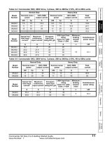
10.4 Maximum continuous output current
The drive models are listed as having the maximum continuous output currents (FLC)
shown in Table 10-1, Table 10-2, Table 10-3 and Table 10-4 (see the Commander SK
Technical Data Guide for details).
Table 10-1 Maximum continuous output current (200V drives)
Table 10-2 Maximum continuous output current (400V drives)
Table 10-3 Maximum continuous output current (575V drives)
Table 10-4 Maximum continuous output current (690V drives)
10.5 Safety label
The safety label supplied with the connectors and mounting brackets must be placed on
a fixed part inside the drive enclosure where it can be seen clearly by maintenance
personnel for UL compliance.
The label clearly states “CAUTION Risk of Electric Shock Power down unit 10 minutes
before removing cover”.
Model FLC (A) Model FLC (A)
SK2201 15.5 SK4201 68
SK2202 22 SK4202 80
SK2203 28 SK4203 104
SK3201 42
SK3202 54
Model FLC (A) Model FLC (A)
SK2401 15.3 SK4401 68
SK2402 21 SK4402 83
SK2403 29 SK4403 104
SK2404 29 SK5401 138
SK3401 35 SK5402 168
SK3402 43 SK6401 205
SK3403 56 SK6402 236
Model FLC (A) Model FLC (A)
SK3501 5.4 SK3505 16
SK3502 6.1 SK3506 22
SK3503 8.4 SK3507 27
SK3504 11
Model FLC (A) Model FLC (A)
SK4601 22 SK5601 84
SK4602 27 SK5602 99
SK4603 36 SK6601 125
SK4604 43 SK6602 144
SK4605 52
SK4606 62
0472-0064-07
T1
T2
T3
T4
0V
Remote current speed
reference input (A1)
+10V reference output
Local voltage speed
reference input (A2)
B1
B2
B3
B4
B5
B6
B7
+24V output
Drive Enable/Reset
Run Forward
Run Reverse
Local (A2)/Remote (A1)
speed reference select
Remote speed
reference input
V
_
+
10k
(2kmin)
+24V
0V
Pr 29 = Eur
Analog output
(motor speed)
Digital output
(zero speed)
T5
T6
OK Fault
Pr 29 = USA
T3 T4 T5 T6T1 T2
B3 B4 B5 B6B1 B2 B7
0
V
A
1
+
1
0
V
A
2
1
2
V
0V
+10V reference output
+24V output
Drive Enable/Reset
V
_
+
+24V
0V
Analog output
(motor speed)
Digital output
(zero speed)
Not used
Not used
Not used
Not used
T1
T2
T3
T4
B1
B2
B3
B4
B5
B6
B7
Forward/Reverse