AutoCAD Structural Detailing: Formwork Drawings doc
Bạn đang xem bản rút gọn của tài liệu. Xem và tải ngay bản đầy đủ của tài liệu tại đây (3.61 MB, 213 trang )
User Guide
Autodesk
®
March 2009
© 2009 Autodesk, Inc. All Rights Reserved. Except as otherwise permitted by Autodesk, Inc., this
publication, or parts thereof, may not be reproduced in any form, by any method, for any purpose.
Certain materials included in this publication are reprinted with the permission of the copyright
holder.
Disclaimer
THIS PUBLICATION AND THE INFORMATION CONTAINED HEREIN IS MADE AVAILABLE
BY AUTODESK, INC. “AS IS.” AUTODESK, INC. DISCLAIMS ALL WARRANTIES, EITHER
EXPRESS OR IMPLIED, INCLUDING BUT NOT LIMITED TO ANY IMPLIED WARRANTIES
OF MERCHANTABILITY OR FITNESS FOR A PARTICULAR PURPOSE REGARDING THESE
MATERIALS.
Trademarks
The following are registered trademarks of Autodesk, Inc., in the USA and/or other countries:
Autodesk Robot Structural Analysis, Autodesk Concrete Building Structures, Spreadsheet Calculator, ATC,
AutoCAD, Autodesk, Autodesk Inventor, Autodesk (logo), Buzzsaw,
Design Web Format, DWF, ViewCube, SteeringWheels, and Autodesk Revit.
All other brand names, product names or trademarks belong to their respective holders.
Third Party Software Program Credits
ACIS Copyright© 1989-2001 Spatial Corp. Portions Copyright© 2002 Autodesk, Inc.
Copyright© 1997 Microsoft Corporation. All rights reserved.
International CorrectSpell™ Spelling Correction System© 1995 by Lernout & Hauspie Speech
Products, N.V. All rights reserved.
InstallShield™ 3.0. Copyright© 1997 InstallShield Software Corporation. All rights reserved.
PANTONE® and other Pantone, Inc. trademarks are the property of Pantone, Inc.© Pantone, Inc.,
2002.
Portions Copyright© 1991-1996 Arthur D. Applegate. All rights reserved.
Portions relating to JPEG © Copyright 1991-1998 Thomas G. Lane. All rights reserved. Portions of
this software are based on the work of the Independent JPEG Group.
Portions relating to TIFF © Copyright 1997-1998 Sam Leffler. © Copyright 1991-1997 Silicon
Graphics, Inc. All rights reserved.
Government Use
Use, duplication, or disclosure by the U.S. Government is subject to restrictions as set forth in
FAR 12.212 (Commercial Computer Software-Restricte Rights) and DFAR 227.7202 (Rights in d
Technical Data and Computer Software), as applicable.
AutoCAD ® Structural Detailing - Formwork Drawings - User Guide page: 1
TABLE OF CONTENTS
1. GENERAL DESCRIPTION OF THE PROGRAM 6
1.1. GENERAL DESCRIPTION OF THE PROGRAM 6
1.2. WORK STAGES IN THE PROGRAM 6
1.3. OPTIONS AVAILABLE IN THE MENU 8
1.4. RIBBON 23
2. CONFIGURATION 24
2.1. JOB PREFERENCES 24
2.2. UNITS 25
2.3. DATABASES 26
2.4. OPTIONS 27
2.5. PRIORITIES 28
2.6. POSITION NAME 29
2.7. DIMENSION LINES 30
2.8. GROUP DIMENSION LINE 31
2.9. SIMPLE DIMENSION LINE 33
2.10. FOUNDATION PLAN 34
2.11. STORY PLAN 36
2.12. VERTICAL SECTION 41
2.13. ELEVATION VIEW 43
2.14. 3D VIEW 45
2.15. DETAIL 46
2.16. MODIFICATION OF DRAWING PARAMETERS 47
3. OBJECT INSPECTOR 49
3.1. DESCRIPTION OF OBJECT INSPECTOR 49
3.2. OBJECT INSPECTOR 49
3.3. MODEL TAB 50
3.4. LAYERS - STRUCTURE MODEL 53
3.5. REGISTER LAYER - STRUCTURE MODEL 53
3.6. PARTS EDITION TAB 54
3.7. POSITIONS TAB 54
3.8. PRINTOUTS TAB 57
3.9. STRUCTURAL DETAILING CENTER TAB 57
4. BASIC PARAMETERS OF A BUILDING 58
4.1. BUILDING PROPERTIES 58
4.2. STORY NAME 58
5. WORKFRAMES 60
5.1. WORKFRAME 60
5.2. RECTANGULAR WORKFRAME 61
5.3. CIRCULAR WORKFRAME 63
6. DEFINITION OF STRUCTURE ELEMENTS 67
6.1. BEAMS / GROUND BEAMS 67
6.1.1. Beam / ground beam - definition 67
6.1.2. Beam - section 68
6.1.3. Beam - vertical definition 69
6.1.4. Beam - details 70
6.1.5. Beam definition - command line 71
© 2009 Autodesk, Inc. All rights reserved
page: 2 AutoCAD ® Structural Detailing - Formwork Drawings - User Guide
6.2. WALLS 72
6.2.1. Wall - definition 72
6.2.2. Wall - section 73
6.2.3. Wall - vertical definition 74
6.2.4. Wall definition - command line 75
6.2.5. Definition rule - offset different from zero 76
6.3. COLUMNS 77
6.3.1. Column - definition 77
6.3.2. Column - section 78
6.3.3. Column - vertical definition 79
6.3.4. Column definition - command line 80
6.4. FLOOR SLABS / RAFT FOUNDATIONS 80
6.4.1. Floor slab / raft foundation - definition 80
6.4.2. Slab - section 81
6.4.3. Slab - vertical definition 82
6.4.4. Slab - details 83
6.4.5. Slab definition - command line 84
6.5. SPREAD FOOTINGS 85
6.5.1. Spread footing - definition 85
6.5.2. Spread footing - section 86
6.5.3. Spread footing - vertical definition 86
6.5.4. Spread footing definition - command line 87
6.6. CONTINUOUS FOOTINGS 88
6.6.1. Continuous footing - definition 88
6.6.2. Continuous footing - section 89
6.6.3. Continuous footing - vertical definition 90
6.6.4. Continuous footing - details 91
6.6.5. Continuous footing definition - command line 91
6.7. DOORS 92
6.7.1. Door - definition 92
6.7.2. Door - geometry 93
6.7.3. Door - vertical definition 93
6.7.4. Door definition - command line 94
6.8. WINDOWS 94
6.8.1. Window - definition 94
6.8.2. Window - geometry 95
6.8.3. Window - vertical definition 95
6.8.4. Window definition - command line 96
6.9. OPENINGS/RECESSES - WALLS 96
6.9.1. Opening / recess - definition 96
6.9.2. Opening / recess - geometry 97
6.9.3. Opening/recess - vertical definition 98
6.9.4. Opening definition - command line 98
6.10. OPENINGS/RECESSES - SLABS 99
6.10.1. Opening / recess - definition (slab) 99
6.10.2. Opening/recess - geometry (slab) 100
6.10.3. Opening/recess - details (slab) 101
6.11. LINTELS 101
6.11.1. Lintel - definition 101
6.12. RING BEAMS 103
6.12.1. Ring beam - Definition 103
6.12.2. Ring beam - Section 104
6.12.3. Ring beam - Vertical Definition 105
6.12.4. Ring beam - Details 105
6.13. PREFABRICATED ELEMENTS 106
6.13.1. Prefabricated element / stairs - definition 106
© 2009 Autodesk, Inc. All rights reserved
AutoCAD ® Structural Detailing - Formwork Drawings - User Guide page: 3
6.13.2. Prefabricated element - definition 106
6.13.3. Prefabricated element - section 107
6.13.4. Prefabricated element - vertical definition 109
6.14. STAIRS 110
6.14.1. Stairs - definition 110
6.14.2. Stairs - section 111
6.14.3. Stairs - vertical definition 111
6.15. PLANES 112
6.15.1. Definition of planes 112
6.15.2. Definition of planes - intermediate horizontal plane 113
6.15.3. Definition of planes - inclined plane of a defined shape and inclination 114
6.15.4. Definition of planes - inclined plane 115
6.15.5. Definition of planes - parameters of plane location 117
6.15.6. Manager of plane properties 117
7. DATABASES 119
7.1. AVAILABLE DATABASES 119
7.1.1. Databases 119
7.1.2. List of cross-sections 119
7.1.3. Material list 121
7.1.4. Prices of formworks and materials 122
7.1.5. Opening list (doors, windows, remaining openings) 122
7.2. DATABASES OF VOLUMETRIC ELEMENTS 124
7.2.1. Definition of prefabricated elements 124
7.2.2. Prefabricated elements - beams 125
7.2.3. Prefabricated elements - columns 126
7.2.4. Prefabricated elements - spread footings 128
7.2.5. Prefabricated elements - stairs 132
7.3. DEFINITION / MODIFICATION OF DATABASE ELEMENTS 132
7.3.1. Definition / modification of sections and openings 132
7.3.2. Definition / modification of a cross-section 133
7.3.3. Definition / modification of a material 134
7.3.4. Definition / modification of openings 135
8. ELEMENT POSITIONING 137
8.1. POSITIONING OF STRUCTURE ELEMENTS 137
8.2. AUTOMATIC POSITIONING 137
9. STYLES OF ELEMENT GRAPHIC DISPLAY 140
9.1. GRAPHIC REPRESENTATION OF STRUCTURE ELEMENTS 140
10. CREATING OF STRUCTURE VIEWS 142
10.1. VIEWS / PLANS CREATED FOR A STRUCTURE MODEL 142
10.2. CREATING OF A PLAN (PROJECTION) OF A BUILDING STORY 142
10.3. CREATING OF A PLAN (PROJECTION) OF FOUNDATIONS 143
10.4. CREATING OF A VERTICAL SECTION OF A BUILDING 144
10.5. CREATING OF AN ELEVATION VIEW OF A BUILDING 145
10.6. CREATING OF A 3D VIEW OF A BUILDING 146
10.7. LAYERS - DRAWING POSITIONS 146
10.8. REGISTER LAYER - DRAWING POSITIONS 147
11. DESCRIPTION OF STRUCTURE ELEMENTS 148
11.1. ELEMENT DESCRIPTIONS 148
11.2. DESCRIPTION STYLES 148
11.2.1. Styles of element description 148
11.2.2. Description style - definition 149
© 2009 Autodesk, Inc. All rights reserved
page: 4 AutoCAD ® Structural Detailing - Formwork Drawings - User Guide
11.2.3. Description elements 150
11.2.4. Description syntax 152
11.2.5. User description - mechanisms of the AutoCAD program 154
12. GRAPHIC SYMBOLS 155
12.1. HOW TO INSERT GRAPHIC SYMBOLS 155
12.2. STYLES OF GRAPHIC SYMBOLS 155
12.2.1. Styles of symbols 155
12.2.2. Axis 156
12.2.3. Elevation mark 157
12.2.4. Section symbol 158
12.2.5. Graphic designation 158
12.2.6. Intersecting line 160
12.2.7. Opening symbol in view 160
12.2.8. Opening symbol in cross-section 161
12.2.9. Symbol of main direction of the slab 162
12.2.10. Detail symbol 163
13. STYLES OF DRAWING TEMPLATES 164
13.1. DRAWING TEMPLATE MANAGER 164
13.2. ADJOINING ELEMENTS 165
13.3. GRAPHIC PRESENTATION 169
13.4. SECTION / VIEW - PARAMETERS 171
13.5. DRAWING LAYOUT 172
13.6. DRAWING COMPONENTS 175
14. SUMMARY TABLES 182
14.1. SUMMARY TABLES (STYLE MANAGER) 182
14.2. DEFINITION/MODIFICATION OF A SUMMARY TABLE STYLE 183
14.2.1. Definition/modification of a table style 183
14.2.2. Table: components and layout 183
14.2.3. Font, color, line 184
14.2.4. Options 185
14.2.5. Sorting and detailed options 186
15. PRINTOUT - TABLES 187
15.1. TABLE PRINTOUT MANAGER 187
15.2. TABLE COMPOSITION 188
15.3. PAGE SETUP 189
15.4. FRAMES 189
15.5. DISTANCES 190
15.6. COLORS AND FORMATS 190
15.7. HEADER 191
15.8. FOOTER 191
15.9. PARAMETERS 192
15.10. TEMPLATES 194
16. DRAWINGS 195
16.1. FORMWORK DRAWING WIZARD 195
16.2. EXPORT OF FORMWORK DRAWINGS TO DWG 195
16.3. EXPORT OF FORMWORK DRAWINGS TO AUTOCAD STRUCTURAL DETAILING
- REINFORCEMENT 196
16.4. AUTOMATIC REINFORCEMENT 200
17. TOOLS 202
17.1. COPY STORY 202
© 2009 Autodesk, Inc. All rights reserved
AutoCAD ® Structural Detailing - Formwork Drawings - User Guide page: 5
17.2. COPY / MOVE SELECTED ELEMENTS 202
17.3. FILTERS - ELEMENT SELECTION BY TYPE 203
17.4. FILTERS - ELEMENT SELECTION BY SECTION 204
17.5. FILTERS - ELEMENT SELECTION 205
17.6. MODIFICATION 206
17.6.1. Wall - modification of element graphic representation 206
17.6.2. Beam / ground beam - modification of element graphic representation 206
17.6.3. Column - modification of element graphic representation 207
17.6.4. Slab/raft foundation - modification of element graphic representation 208
17.6.5. Spread footing - modification of element graphic representation 208
17.6.6. Continuous footing - modification of element graphic representation 209
17.6.7. Openings (windows, doors) - modification of element graphic representation 210
18. EXAMPLE - PROCEDURE WHILE WORKING IN THE PROGRAM 211
18.1. SHORT EXAMPLE - USE OF AUTOCAD STRUCTURAL DETAILING - FORMWORK DRAWINGS 211
© 2009 Autodesk, Inc. All rights reserved
page: 6 AutoCAD ® Structural Detailing - Formwork Drawings - User Guide
1. GENERAL DESCRIPTION OF THE PROGRAM
1.1. General description of the program
AutoCAD Structural Detailing - Formwork Drawings has been developed to make it easier to
prepare formwork drawings (plans of arrangement of structural positions) of structure components.
AutoCAD Structural Detailing - Formwork Drawings is the program for defining a structure
model, creating drawings (sections, views, projections), creating formwork drawings of single
structure elements, preparing tables of material elements and estimating costs of a structure.
AutoCAD Structural Detailing - Formwork Drawings allows making detailed drawings of a
structure (story plans, foundation plans, sections, elevation views, etc.); it is equipped with a
complete set of options for drawing and description of structure elements, that are adapted to the
needs of an engineer / designer.
The program may be used as:
• a program for exporting elements of a structure model to AutoCAD Structural Detailing -
Reinforcement and generating required reinforcement
• a tool to use when preparing bids (quick modeling, cost estimation).
AutoCAD Structural Detailing - Formwork Drawings combined with the program AutoCAD
Structural Detailing - Reinforcement allows preparing a complete structure project and
generating detailed drawings with the possibility to edit prepared drawings.
Basic functions of AutoCAD Structural Detailing - Formwork Drawings are:
a) definition of a structure model
b) creating formwork drawings (single structure elements, story plans, elevation views, etc.)
c) export of structure model elements to AutoCAD Structural Detailing - Reinforcement.
The following objects are singled out in the program:
• Structure model, structure model elements - real structure elements (3D); detailed drawings
are created for them
• Position - an object concerned with organization of structure model elements; a (letter - digit)
designation of identical elements in a structure
• Document - a set of views of a position in specified projections and views (any number of
documents may be generated for each position); a document consists of views. NOTE: A
document may be edited only in the edition layout; a document may be printed only after it is
inserted to the printout layout.
• View - a single drawing; it is always a document component - if it has been added to a
printout, it is a printout element at the same time. NOTE: only a view (drawing) placed in the
printout layout may be printed
• Printout - ready-to-use printout composed of views; its equivalent in the AutoCAD ® program
is a layout together with AutoCAD views placed in it; for each printout there is exactly one
layout corresponding to it.
The listed elements are concerned with the stages of work on a project.
1.2. Work stages in the program
AutoCAD Structural Detailing - Formwork Drawings is a program for creating drawings of
buildings (elevation drawings, plans of stories, plans of foundations, sections, etc.). Creation of
drawings in the program is an automated process. Drawings are created based on a 3D model of
a real building which is defined using the options available in AutoCAD Structural Detailing -
Formwork Drawings. Since AutoCAD Structural Detailing - Formwork Drawings works on the
AutoCAD ® platform, there is also a possibility to use the options available in that program (e.g.
edit operations such as copying, moving, etc.).
© 2009 Autodesk, Inc. All rights reserved
AutoCAD ® Structural Detailing - Formwork Drawings - User Guide page: 7
Creation of a building model and its drawings can be divided into the following stages:
1. defining a model / loading a model from other programs
Structure model includes three-dimensional elements of a real 3D structure; drawings will be
prepared for these elements.
Definition of the model consists in determining the locations of structural elements of a
building, such as: beams, columns, walls, slabs, foundations, etc.
See – definition of basic structure elements:
Walls
Columns
Beams
Slabs
Spread footings
Continuous footings
Doors
Windows
Lintels
Databases
2. assigning positions to structure elements
Assigning - to elements of a structure model - positions (an object concerned with
organization of structure model elements; one or several structure elements are assigned a
position for which a common set of drawings may be generated). Positions are available on
the two tabs of the Object Inspector dialog box: Model and Positions.
See:
Positioning of elements of a structure model
Automatic positioning
3. automatic creation of drawings of a building model
Once positions are assigned to model elements, the program automatically creates
drawings of a building based on the configurable templates which define projections,
scales, appearance of descriptions, symbols and other parameters concerning graphic
representation of an element in a drawing – see:
creating a story plan
creating a foundation plan
creating a 3D view
creating an elevation view
creating a vertical section.
Drawings can be edited using the tools available in AutoCAD Structural Detailing -
Formwork Drawings or the AutoCAD ® standard options. In the case of model
modifications, it is possible to automatically update created drawings.
4. export of model elements to other programs / printouts
The following possibilities are offered here:
- saving of formwork drawings of individual structure elements in a DWG file
- export of formwork drawings of structure elements to AutoCAD Structural Detailing -
Reinforcement
- automatic generation of reinforcement and drawings of structure element reinforcements
in AutoCAD Structural Detailing - Reinforcement.
© 2009 Autodesk, Inc. All rights reserved
page: 8 AutoCAD ® Structural Detailing - Formwork Drawings - User Guide
1.3. Options available in the menu
Below is a list of all options available in AutoCAD Structural Detailing - Formwork Drawings.
The list includes location of options in the text menu, icons that represent particular options,
commands that activate options from the command line and short descriptions of options.
Definition
Wall
Opens the Wall: definition dialog box; the option enables definition of walls
in a structure model.
Menu: Formwork Drawings / Define / Wall command
Command line: RBCX_DEF_WALL
Column
Opens the Wall: definition dialog box; the option enables definition of
columns in a structure model.
Menu: Formwork Drawings / Define / Column command
Command line: RBCX_DEF_COL.
Beam
Opens the Beam: definition dialog box; the option enables definition of
beams in a structure model.
Menu: Formwork Drawings / Define / Beam command
Command line: RBCX_DEF_BEAM
Slab
Opens the Slab: definition dialog box; the option enables definition of floor
slabs in a structure model.
Menu: Formwork Drawings / Define / Slab command
Command line: RBCX_DEF_SLAB
Stairs
Opens the Stairs: definition dialog box; the option enables definition of
stairs in a structure model.
Menu: Formwork Drawings / Define / Stairs command
Command line: RBCX_DEF_STAIRS
Ring beam
Opens the Ring beam: definition dialog; use this option to define ring
beams in a structure model.
Menu: Formwork Drawings / Define / Ring Beam command
Command line: RBCX_DEF_RING_BEAM
Door
Opens the Door: definition dialog box after indicating a wall; the option is
used to define door openings in selected elements of a structure model.
Menu: Formwork Drawings / Define / Doors command
Command line: RBCX_DEF_DOOR.
Window
Opens the Window: definition dialog box after indicating a wall; the option
is used to define window openings in selected elements of a structure
model.
Menu: Formwork Drawings / Define / Window command
Command line: RBCX_DEF_WINDOW.
Lintel
Opens the Lintel: definition dialog box after selecting a window, door,
recess or opening in the wall; the option is used to define lintels above the
selected elements of a structure model.
Menu: Formwork Drawings / Define / Lintel command
Command line: RBCX_DEF_LINTEL
© 2009 Autodesk, Inc. All rights reserved
AutoCAD ® Structural Detailing - Formwork Drawings - User Guide page: 9
Opening/recess in
wall
Opens the Opening: definition dialog box after indicating a structure
element (wall); the option is used to define an opening/recess in the
selected walls of a structure.
Menu: Formwork Drawings / Define / Opening/recess in wall command
Command line: RBCX_DEF_HOLE_WALL.
Opening/recess in
slab
Opens the Opening: definition dialog box after indicating a structure
element (slab); the option is used to define an opening/recess in the
selected slabs of a structure model.
Menu: Formwork Drawings / Define / Opening/recess in slab command
Command line: RBCX_DEF_HOLE_SLAB
Spread footing
Opens the Spread footing: definition dialog box; the option enables
definition of spread footings in a structure model.
Menu: Formwork Drawings / Define / Spread footing command
Command line: RBCX_DEF_FOOT.
Continuous footing
Opens the Continuous footing: definition dialog box; the option enables
definition of continuous footings in a structure model.
Menu: Formwork Drawings / Define / Continuous footing command
Command line: RBCX_DEF_CONT_FOOT.
Ground beam
Opens the Ground beam: definition dialog box; the option enables
definition of ground beams in a structure model.
Menu: Formwork Drawings / Define / Ground beam command
Command line: RBCX_DEF_GROUND_BEAM
Raft foundation
Opens the Raft foundation: definition dialog box; the option enables
definition of raft foundations in a structure model.
Menu: Formwork Drawings / Define / Raft foundation command
Command line: RBCX_DEF_SLAB_FOUNDATION
Prefabricated
element
Opens the Prefabricated element: definition dialog box; the option
enables definition of prefabricated elements in a structure model.
Prefabricated elements are volumetric elements of complex geometry
(spread footings, stairs, beams, columns, etc.).
Menu: Formwork Drawings / Define / Prefabricated element command
Command line: RBCX_DEF_PREF
Add group
Select this option to define a group, that is a set of structure model
elements; a group is a user-defined set of elements with the specified
name. It allows generating drawings for a defined set of structure elements.
Using this option you can also define reinforcement (common reinforcement
for elements of the group, dowel reinforcement and so on) for elements that
belong to the group. Typical examples of groups defined from different
structure elements are:
1. a frame that consists of beams, columns and spread footings
2. slab for other structure elements.
To define a group:
1. select elements of the group
2. specify the group name.
Structure elements can belong to several groups. A defined group is saved
in the Object Inspector pane; after creating a first group, a new category
Groups displays in Object Inspector.
© 2009 Autodesk, Inc. All rights reserved
page: 10 AutoCAD ® Structural Detailing - Formwork Drawings - User Guide
A first selected element of a structure is treated as the main element of a
group (it is marked in Object Inspector). Selecting the main element is
important when drawings are generated for a group. Individual plans are
created in relation to the main element of a group.
Operations on groups (that is adding an element, selecting the main
element or deleting an element) are performed in the Object Inspector
pane.
Menu: Formwork Drawings / Define / Add group command
Command line: RBCX_ADDGROUP
Workframes
Insert rectangular
workframe
Opens the Workframe dialog box where parameters of a rectangular
workframe can be defined.
Menu: Formwork Drawings / Workframes / Insert rectangular workframe
command
Command line: RBCX_DEF_WORKFRAME
Insert circular
workframe
Opens the Workframe dialog box where parameters of a circular
workframe can be defined.
Menu: Formwork Drawings / Workframes / Insert circular workframe
command
Command line: RBCX_DEF_WORKFRAME_RADIAL
Insert structural axis
The option is used to insert an axis in a selected place in a drawing.
Symbols are drawn according to a default style set in the Job Preferences
dialog box. To insert a structural axis symbol in a drawing, follow the steps
below:
1 select the Formwork Drawings / Insert structural axis command
2 enter a number (name) of a structural axis
3 indicate the first point of an axis symbol
4 indicate the second point of the axis symbol (see the drawing below)
5 if need be, determine the order allowing insertion of axes in groups.
A number of the axis is proposed according to the settings in the default
style; while inserting the axis the user may enter any number (each
following one will be inserted according to the recently-specified
numbering). There is a possibility to modify the axis number using the
relevant option from the context menu.
Menu: Formwork Drawings / Insert structural axis command
Command line: RBCX_DEF_SYMBOL_AXIS
Planes
Definition of plane
Opens the Definition of planes dialog box. The option enables defining
intermediate (horizontal) planes or inclined planes on which elements of a
structure model can be defined.
Menu: Formwork Drawings / Planes / Definition of plane command
Command line: RBCX_PLANE_DEF
© 2009 Autodesk, Inc. All rights reserved
AutoCAD ® Structural Detailing - Formwork Drawings - User Guide page: 11
Attach to plane
The option allows attaching selected structure elements to an indicated
inclined plane. Geometry of structure elements is adjusted to the slope of
the inclined plane.
Menu: Formwork Drawings / Planes / Attach to plane command
Command line: RBCX_ATTACH_TO_PLANE
Detach from plane
The option allows ‘detaching’ selected structure elements from an indicated
inclined plane (the option has the opposite action to the Attach to plane
option). The operation results in ‘returning’ elements to default levels of the
reference plane.
Menu: Formwork Drawings / Planes / Detach from plane command
Command line: RBCX_DETACH_FROM_PLANE
Group planes
The option allows creating a group of planes; such a group is regarded as a
separate object which enables defining elements of a structure model with
a complicated plane geometry (e.g. planes of a multi-pitch roof).
To obtain a group of planes, the user should indicate planes that should
belong to the group of planes, and next, specify a name of the group of
planes. Once created, the group of planes is regarded in the same way as
a standard single plane.
Menu: Formwork Drawings / Planes / Group planes command
Command line: RBCX_GROUP_PLANES
Ungroup planes
The option allows ‘splitting’ a group of planes into single separate planes
(the option has the opposite action to the Group planes option).
Menu: Formwork Drawings / Planes / Ungroup planes command
Command line: RBCX_UNGROUP_PLANES
Import/Export
Import structure
from Autodesk CBS
The option allows import of a structure model created in Autodesk
Concrete Building Structures.
Menu: Formwork Drawings / Import\Export / Import structure from
Autodesk CBS command
Command line: RBCX_LOAD_ROBIN_MODEL
Export structure to
Autodesk CBS
The option allows opening Autodesk Concrete Building Structures and
saving a structure model in the format of this program.
Menu: Formwork Drawings / Import\Export / Export structure to Autodesk
CBS command
Command line: RBCX_SAVE_ROBIN_MODEL
Save model as ACIS
solids
The option allows saving a structure model as an ACIS solid (as a drawing
in a DWG format).
Menu: Formwork Drawings / Import\Export / Save model as ACIS solids
command
Command line: RBCX_ACIS_EXPORT
Display
Show whole building
A whole structure model is presented on the screen.
Menu: Formwork Drawings / Display / Show whole building command
Command line: RBCX_VIEW_BUILDING
Show active story
After selecting this option, only an active (selected) story of a building will
be presented on the screen.
Menu: Formwork Drawings / Display / Show active story command
Command line: RBCX_VIEW_STOREY
© 2009 Autodesk, Inc. All rights reserved
page: 12 AutoCAD ® Structural Detailing - Formwork Drawings - User Guide
Show only selected
elements
After selecting this option, only selected elements of a building will be
presented on the screen.
Menu: Formwork Drawings / Display / Show only selected elements
command
Command line: RBCX_VIEW_SELECT_EL
Show elements
Selecting this option opens the Filters - element selection dialog box; the
option is used to define criteria of selecting elements in a structure model.
Menu: Formwork Drawings / Display / Show elements command
Command line: RBCX_VIEW_ELEMENTS
Show planes
Selecting this option opens the Manager of plane properties dialog box;
the option is used for viewing and editing parameters of defined
intermediate or inclined planes.
Menu: Formwork Drawings / Display / Show planes command
Command line: RBCX_EDIT_PLANES
Create plan of story
After selecting this option the program automatically creates a plan of a
selected story in a building.
Menu: Formwork Drawings / Create plan of story command
Command line: RBCX_DEF_STOREY_VIEW
Create plan of
foundation
After selecting this option the program automatically creates a plan of
building foundations.
Menu: Formwork Drawings / Create plan of foundation command
Command line: RBCX_DEF_FOUNDATION_VIEW
Create vertical
section
After selecting this option the program automatically creates a vertical
section of a structure model; to create a vertical section, indicate lines
intersecting a structure model and a section ‘depth’.
Menu: Formwork Drawings / Create vertical section command
Command line: RBCX_DEF_V_SECTION
Create elevation
view
After selecting this option the program automatically creates an elevation
view of a structure model; to create an elevation view, indicate lines of the
elevation view and a direction of the view.
Menu: Formwork Drawings /Create elevation view command
Command line: RBCX_DEF_ELEVATION
Create 3D view
After selecting this option the program automatically creates a three-
dimensional view of a structure model;
Menu: Formwork Drawings /Create 3D view command
Command line: RBCX_DEF_VIEW3D
Create a drawing
detail
Select this option to automatically generate a detail in drawings. This type
of drawing can be widely used in the structure documentation which
necessitates preparing drawings (using a more accurate scale) of details of
the contact between elements or connections of elements. A detail is a
specific type of document; it is created based on another document (a
source document). It is usually created in relation to the plan (of story or
foundation) or the vertical section.
A detail drawing inherits all settings from the source document (see also:
Job preferences / Detail, Detail Style).
To create a detail:
© 2009 Autodesk, Inc. All rights reserved
AutoCAD ® Structural Detailing - Formwork Drawings - User Guide page: 13
1. move to the Edition Layout (from the level of a user-selected document)
2. select the place and circle the area to be included in the detail.
A circle that indicates the detail is drawn in the source document (the
document where the detail location was selected).
NOTE: A detail drawing presents elements to the extent limited by the
square inscribed in the specified circle.
Names of subsequent details are unique in the project.
A detail is added to the list in the Object Inspector pane; it is under the
document it was created from.
Menu: Formwork Drawings / Create a drawing detail command
Command line: RBCX_DEF_DETAIL
Element description
The option allows description of individual objects in a structure;
descriptions of structure elements are possible in plans (of stories or
foundations) and in sections.
Menu: Formwork Drawings / Element description command
Command line: RBCX_LABEL
Group description
Use this option to describe defined groups of structure elements;
descriptions of groups can be placed in plans (of stories or foundations),
views and sections.
To describe a group in the drawing, select any edge of the group element
(you can select a part of or whole drawing using a window). If an element
belongs to several groups, all groups are described. Groups are described
according to the style in element description styles.
Menu: Formwork Drawings / Group description command
Command line: RBCX_GROUP_LABEL
Dimension lines
Group dimension
line
The Group dimension line option is used to create dimension lines for
structure elements presented in created plans or sections of a designed
object. The user should indicate elements to be dimensioned and define an
offset of a dimension line from dimensioned elements. The program will
automatically recognize selected elements and appropriately group
dimension lines.
Menu: Formwork Drawings / Dimension lines / Group dimension line
command
Command line: RBCX_DIM_GROUP
Simple dimension
line
The Simple dimension line option is used to create dimension lines for
individual structure elements located in generated plans or sections of a
designed object; the user should indicate an element(s) to be dimensioned
(intersect the element with an auxiliary line) and define an offset of a
dimension line from the dimensioned element.
Menu: Formwork Drawings / Dimension lines / Simple dimension line
command
Command line: RBCX_DIM_SIMPLE
Arc dimension line
The Arc dimension line option is used to create dimension lines for arc-
shaped structure elements (walls, beams, continuous footings) located in
generated plans or sections of a designed object; the user should indicate
one arc element to be dimensioned and define an offset of a dimension line
from the dimensioned element.
Menu: Formwork Drawings / Dimension lines / Arc dimension line
command
Command line: RBCX_DIM_ARC
© 2009 Autodesk, Inc. All rights reserved
page: 14 AutoCAD ® Structural Detailing - Formwork Drawings - User Guide
Add division point
The option allows modifying dimension lines created by the program by
defining additional points (auxiliary lines) to which a given dimension will
refer. Dimensions presented on the dimension line will be recalculated and
adjusted to the location of a new point on the dimension line (see the
drawing below).
Before adding a line
After adding a line
Menu: Formwork Drawings / Dimension lines / Add division point
command
Command line: RBCX_DIM_UTIL_ADD
Delete division point
The option allows modifying dimension lines created by the program by
deleting indicated points (auxiliary lines) on a dimension line. Once a point
(auxiliary line) is deleted from a dimension line, dimensions on the
dimension line will be recalculated (see the drawing below).
Before deleting a line
© 2009 Autodesk, Inc. All rights reserved
AutoCAD ® Structural Detailing - Formwork Drawings - User Guide page: 15
After deleting a line
Menu: Formwork Drawings / Dimension lines / Delete division point
command
Command line: RBCX_DIM_UTIL_DEL
Insert elevation mark
The option is used to insert an elevation mark in a selected place in a
drawing. Symbols are drawn according to a default style set in the Styles
of symbols dialog box. To insert an elevation mark in a drawing, follow the
steps below:
1 select the Formwork Drawings / Insert elevation mark command
2 indicate a point on a selected level (the program will automatically
calculate the height with respect to the base point).
Levels are designated with respect to the base level defined in the Building
parameters dialog box.
Menu: Formwork Drawings / Insert elevation mark command
Command line: RBCT_DEF_SYMBOL_COTE
Insert symbol of
main direction
Use this option to insert a symbol of main direction for slabs. Symbols are
drawn according to a default style set in the Styles of symbols dialog.
You can perform this operation in the Edition Layout.
Menu: Formwork Drawings / Insert symbol of main direction command
Command line: RBCX_SLAB_MAIN_DIR
Insert opening
symbol in view
The option is used to insert an opening symbol at a selected place in a
drawing. Symbols are drawn according to a default style set in the Styles
of symbols dialog box. To insert an opening symbol in a view, follow the
steps below:
1 select the Formwork Drawings / Insert opening symbol in view command
2 select a point inside the opening in the view.
Menu: Formwork Drawings / Insert opening symbol in view command
Command line: RBCT_DEF_SYMBOL_HOLE
Insert opening
symbol in cross-
section
The option is used to insert an opening symbol in the cross-section.
Symbols are drawn according to a default style set in the Styles of
symbols dialog box.
Menu: Formwork Drawings / Insert opening symbol in cross-section
command
Command line: RBCT_DEF_SYMBOL_HOLECAST
Select labels and
dimensions
Opens the Filters – element selection dialog box; the option is used to
define criteria of selection of labels and dimensions of structure objects.
Labels (descriptions) of structure elements are available in plans (of stories
or foundations) and in sections.
Menu: Formwork Drawings / Select labels and dimensions command
Command line: RBCX_LABEL_SELECT
© 2009 Autodesk, Inc. All rights reserved
page: 16 AutoCAD ® Structural Detailing - Formwork Drawings - User Guide
Change size of labels
and dimensions
The option allows specifying a scale factor for labels and dimensions of
structure objects. After indicating a label or dimension of a structure
element, the user should define a factor value by which the size of a label
or dimension will be multiplied; the option is available in the edition layout.
Menu: Formwork Drawings / Change size of labels and dimensions
command
Command line: RBCX_MOD_LABEL_SCALE
Tables
Summary - elements
After running this option, the element summary table is inserted in a
drawing. This table may be inserted for:
- whole building (all model elements)
- selected model elements
- filtered model elements.
NOTE: The table may be added only to a completed printout (generated
drawing); it cannot be inserted to a structure model or to the edit layout.
Menu: Formwork Drawings / Tables / Summary - elements command
Command line: RBCX_LIST_ELEM
Summary - costs
After running this option, the summary table of element costs is inserted in
a drawing. This table may be inserted for:
- whole building (all model elements)
- selected model elements
- filtered model elements.
NOTE: The table may be added only to a completed printout (generated
drawing); it cannot be inserted to a structure model or to the edit layout.
Menu: Formwork Drawings / Tables / Summary - costs command
Command line: RBCX_LIST_PRICE
Detailed - elements
After running this option, the detailed element table (this table includes both
summary tables) is inserted in a drawing. This table may be inserted for:
- whole building (all model elements)
- selected model elements
- filtered model elements.
NOTE: The table may be added only to a completed printout (generated
drawing); it cannot be inserted to a structure model or to the edit layout.
Menu: Formwork Drawings / Tables / Detailed - elements command
Command line: RBCX_LIST_DETA
Detailed - openings
After running this option, a detailed table concerned with openings is
inserted in a drawing. This table may be inserted for:
- whole building (all model elements)
- selected model elements
- filtered model elements.
NOTE: The table may be added only to a completed printout (generated
drawing); it cannot be inserted to a structure model or to the edition layout.
Menu: Formwork Drawings / Tables / Detailed - openings command
Command line: RBCX_LIST_HOLE
Summary - groups
Select this option to insert to a drawing a summary table for a specified
selection of groups or for all groups.
A summary table includes basic data for a group, such as a volume or area
© 2009 Autodesk, Inc. All rights reserved
AutoCAD ® Structural Detailing - Formwork Drawings - User Guide page: 17
of the group as a whole.
Menu: Formwork Drawings / Tables / Summary - groups command
Command line: RBCX_LIST_GRSUM
Detailed - groups
Select this option to insert to a drawing a detailed table for a specified
selection of groups or for all groups.
A detailed table lists elements of the group and their basic data.
Menu: Formwork Drawings / Tables / Detailed - groups command
Command line: RBCX_LIST_GRDET
Update table
After the option is switched on, the program updates an indicated table after
changes made in geometry / parameters of a structure model.
Menu: Formwork Drawings / Tables / Update table command
Command line: RBCX_LIST_ACT
Table Printout /
Export / Edit
The option allows printing a table or exporting a table to an *.xls or *.csv
format file.
Menu: Formwork Drawings / Tables / Table Printout / Export / Edit
command
Command line: RBCX_LIST_EXP
Styles
Element description
styles
Opens the Description Styles dialog box; the option allows defining styles
(format) of description for individual elements of a structure model.
Menu: Formwork Drawings / Styles / Element description styles command
Command line: RBCX_STYLE_LABEL
Styles - tables
Opens the Summary tables - style manager dialog box; the option allows
defining/modifying summary tables for structure model elements.
Menu: Formwork Drawings / Styles / Styles - tables command
Command line: RBCX_STYLE_LIST
Styles - graphic
symbols
Opens the Styles of symbols dialog box; the option allows defining styles
(format) of symbols presented in structure drawings (elevation mark,
structural axis symbol).
Menu: Formwork Drawings / Styles / Styles – graphic symbols command
Command line: RBCT_DEF_SYMBOL_STYLE.
Styles – element
graphic display
Opens the Structure model – graphic representation of elements dialog
box; the option allows defining the manner of representing structure model
elements on the screen (line thickness and type, colors, etc.).
Menu: Formwork Drawings / Styles / Styles - element graphic display
command
Command line: RBCX_STYLE_GRAPHIC_PRESENTATION
Styles – drawing
templates
Opens the Drawing template manager dialog box; the option allows
determining a method of creating formwork drawings of elements of a
building structure.
Menu: Formwork Drawings / Styles / Styles – drawing templates command
Command line: RBCX_DRAWING_LAYOUT_MNGR
Databases
Section database
Opens the Section list dialog box; the options provided in this dialog box
allow the user to:
= define a new section shape
= open external section databases (e.g. Robot databases)
= save defined sections in a database (*.mdb file).
© 2009 Autodesk, Inc. All rights reserved
page: 18 AutoCAD ® Structural Detailing - Formwork Drawings - User Guide
Menu: Formwork Drawings / Databases / Section database command
Command line: RBCX_TOOL_BASE_SECT
Material database
Opens the Material list dialog box; the options provided in this dialog box
allow the user to:
= define a new material type
= open external material databases (e.g. Robot databases)
= save defined materials in a database (*.mdb file).
Menu: Formwork Drawings / Databases / Material database command
Command line: RBCX_TOOL_BASE_MAT
Spread footing
database
Opens the Spread footing list dialog box (prefabricated elements, i.e.
solids of complex geometry); the options provided in this dialog box allow
the user to:
= define a new shape of a spread footing
= open files with definitions of spread footings
= save defined solid shapes in a database.
Menu: Formwork Drawings / Databases / Spread footing database
command
Command line: RBCX_TOOL_BASE_SOLID
Stairs database
Opens the dialog box List of stairs (prefabricated elements, i.e. solids of
complex geometry); the options provided in the dialog box allow the user to:
= define a new shape of stairs
= open files with definitions of stairs
= save defined stair shapes in a database.
Menu: Formwork Drawings / Databases / Stairs database command
Command line: RBCX_TOOL_BASE_SOLID
Prefabricated
element database
Beam database
Opens the dialog box Prefabricated beam list (prefabricated elements, i.e.
solids of complex geometry); the options provided in this dialog box allow
the user to:
= define a new shape of a prefabricated beam
= open files with definitions of prefabricated beams
= save defined shapes of prefabricated beams in a database.
Menu: Formwork Drawings / Databases / Prefabricated element database
/ Beam database command
Command line: RBCX_TOOL_BASE_PREF_BEAM
Column database
Opens the dialog box Prefabricated column list (prefabricated elements,
i.e. solids of complex geometry); the options provided in this dialog box
allow the user to:
= define a new shape of a prefabricated column
= open files with definitions of prefabricated columns
= save defined shapes of prefabricated columns in a database.
Menu: Formwork Drawings / Databases / Prefabricated element database
/ Column database command
Command line: RBCX_TOOL_BASE_PREF_COL
Slab database
Opens the dialog box Prefabricated slab list (prefabricated elements, i.e.
solids of complex geometry); the options provided in this dialog box allow
the user to:
= define a new shape of a prefabricated slab
= open files with definitions of prefabricated slabs
= save defined shapes of prefabricated slabs in a database.
© 2009 Autodesk, Inc. All rights reserved
AutoCAD ® Structural Detailing - Formwork Drawings - User Guide page: 19
Menu: Formwork Drawings / Databases / Prefabricated element database
/ Slab database command
Command line: RBCX_TOOL_BASE_PREF_SLAB
Wall database
Opens the dialog box Prefabricated wall list (prefabricated elements, i.e.
solids of complex geometry); the options provided in this dialog box allow
the user to:
= define a new shape of a prefabricated wall
= open files with definitions of prefabricated walls
= save defined shapes of prefabricated walls in a database.
Menu: Formwork Drawings / Databases / Prefabricated element database
/ Wall database command
Command line: RBCX_TOOL_BASE_PREF_WALL
Ground beam
database
Opens the dialog box Prefabricated ground beam list (prefabricated
elements, i.e. solids of complex geometry); the options provided in this
dialog box allow the user to:
= define a new shape of a (prefabricated) ground beam
= open files with definitions of (prefabricated) ground beams
= save defined shapes of (prefabricated) ground beams in a database.
Menu: Formwork Drawings / Databases / Prefabricated element database
/ Ground beam database command
Command line: RBCX_TOOL_BASE_PREF_GROUND_BEAM
Continuous footing
database
Opens the dialog box Prefabricated continuous footing list
(prefabricated elements, i.e. solids of complex geometry); the options
provided in this dialog box allow the user to:
= define a new shape of a (prefabricated) continuous footing
= open files with definitions of (prefabricated) continuous footings
= save defined shapes of (prefabricated) continuous footing in a database.
Menu: Formwork Drawings / Databases / Prefabricated element database
/ Continuous footing database command
Command line: RBCX_TOOL_BASE_PREF_CONT_FOOT
Raft foundation
database
Opens the dialog box Prefabricated raft foundation list (prefabricated
elements, i.e. solids of complex geometry); the options provided in this
dialog box allow the user to:
= define a new shape of a (prefabricated) raft foundation
= open files with definitions of (prefabricated) raft foundations
= save defined shapes of (prefabricated) raft foundations in a database.
Menu: Formwork Drawings / Databases / Prefabricated element database
/ Raft foundation database command
Command line: RBCX_TOOL_BASE_PREF_SLAB_FOUNDATION
Window database
Opens the Window list dialog box; the options provided in this dialog box
allow the user to:
= define a new window shape
= open external window databases
= save defined window shapes in a database (*.mdb file).
Menu: Formwork Drawings / Databases / Window database command
Command line: RBCX_TOOL_BASE_WINDOW
Door database
Opens the Door list dialog box; the options provided in this dialog box
allow the user to:
= define a new door shape
© 2009 Autodesk, Inc. All rights reserved
page: 20 AutoCAD ® Structural Detailing - Formwork Drawings - User Guide
= open external door databases
= save defined door shapes in a database (*.mdb file).
Menu: Formwork Drawings / Databases / Door database command
Command line: RBCX_TOOL_BASE_DOOR
Remaining openings
Opens the Opening list dialog box; the options provided in this dialog box
allow the user to:
= define a new opening shape
= open external opening databases
= save defined opening shapes in a database (*.mdb file).
Menu: Formwork Drawings / Databases / Remaining openings command
Command line: RBCX_TOOL_BASE_OPENINGS
Tools
Modify
The option allows modifying parameters of a selected structure element
(parameters of a wall, beam, column, etc.). Once the structure element is
selected, the dialog box appears on the screen where parameters of the
structure element definition (material, geometric parameters, priority, etc.)
may be modified.
Menu: Formwork Drawings / Tools / Modify command
Command line: RBCX_MOD
Modify graphical
parameters
The option allows modification of graphic parameters of a selected structure
element. Once the structure element is selected, the dialog box appears on
the screen where parameters of the structure element presentation (type of
the element contour line, filling, element hatching, etc.) may be modified.
Menu: Formwork Drawings / Tools / Modify graphical parameters
command
Command line: RBCX_MOD_PROP
Element selection by
type
Open the Filters – element selection dialog box; the option is used to
define criteria of selection of elements in a structure model.
Menu: Formwork Drawings / Tools / Element selection by type command
Command line: RBCX_TOOL_SELECT_EL
Element selection by
section
Opens the Filters – element selection dialog box; the option is used to
define criteria of selection of elements in a structure model.
Menu: Formwork Drawings / Tools / Element selection by section
command
Command line: RBCX_TOOL_SELECT_EX
Element info
The option allows displaying information concerning an indicated element.
Once an element is selected, the dialog box with basic information about
the selected element (element type, position, material, length, priority, etc.)
appears on the screen.
Menu: Formwork Drawings / Tools / Element info command
Command line: RBCX_TOOL_INFO
Select group
Use this option to select a group in a structure model. selecting a group or
groups highlights them in the structure model.
After selecting this option, select a selection mode in the command line:
selecting a group or selecting elements of the group. It activates the mode
of operation on the group (such as adding an element) or mode of
operation on elements (such as positioning the elements), respectively.
Menu: Formwork Drawings / Tools / select group command
Command line: RBCX_SELGROUP
© 2009 Autodesk, Inc. All rights reserved
AutoCAD ® Structural Detailing - Formwork Drawings - User Guide page: 21
Refresh structure
model
Use this option to generate a correct structure model and to delete incorrect
items in the model that are associated with connections in a structure
model element (such as intersections of walls with beams / slabs).
NOTE: After performing this operation all documents (story plans, sections
of a building, elevation views, 3D views) are out of date. They need to be
generated again, because elements of a structure model might have been
changed.
Menu: Formwork Drawings / Tools / Refresh structure model command
Command line: RBCX_MODELREFRESH
Modify
Change beam to
ground beam
The option allows swapping:
- a selected beam for a ground beam
- a selected ground beam for a beam.
After swapping them, all parameters determined for a beam/ground beam
are kept (section, position with respect to a story), only the object type
changes.
NOTE: If a beam / ground beam has been positioned, then after a swap,
positioning of such an element should be repeated.
Menu: Formwork Drawings / Modify / Change beam to ground beam
command
Command line: RBCX_TOOL_SWAP_BEAM
Copy / Move
elements
The options allows copying or moving selected structure elements to a new
place indicated by the user. The Copy / Move selected elements dialog
box opens on the screen.
Menu: Formwork Drawings / Modify / Copy /Move elements command
Command line: RBCX_TOOL_COPYOBJECTS
Define opening in a
beam
The option allows defining an opening in a beam, a ground beam or a
continuous footing. To define an opening, the user should:
- indicate a beam, a ground beam or a continuous footing
- in the Opening in a beam - Definition dialog box – select a type and
geometry of an opening in the section of a beam/continuous footing
- indicate the location of an opening along the length of a
beam/continuous footing
Menu: Formwork Drawings / Modify / Define opening in a beam command
Command line: RBCX_TOOL_HOLE_BEAM
Cut beam/wall to
polyline
The option allows cutting a beam, a ground beam, a continuous footing or a
wall to the plane determined by a polyline. To do it, the user should:
- indicate a beam, a ground beam, a continuous footing or a wall
- indicate a polyline defining the cutting plane
- indicate a part of a beam/continuous footing/wall to be cut off.
Menu: Formwork Drawings / Modify / Cut beam/wall to polyline command
Command line: RBCX_TOOL_CUT_POLYLINE
Inclination of slab
surface
Select this option to define inclination of a slab. Using it you can dimension
slabs of varying thickness (previous versions of the software allowed
defining slabs of only constant thickness).
To define inclination of a slab:
1. select a slab
2. select the slab surface (top or bottom)
3. define an offset of the edge or vertex of the slab; the offset is defined in
the perpendicular direction to the slab.
An offset value is specified in work units. An offset with the [+] sign is
directed up (in relation to the building), while the offset with the [-] sign is
© 2009 Autodesk, Inc. All rights reserved
page: 22 AutoCAD ® Structural Detailing - Formwork Drawings - User Guide
directed down.
Offsets of edges or vertexes of the slab are treated as machinings of the
slab. They are saved in Object Inspector on the Parts Edition tab. Offsets
can be deleted from the slab to restore its initial thickness.
Menu: Formwork Drawings / Modify / Inclination of slab surface command
Command line: RBCX_TOOL_INCLINED_PLATE
Merge elements
Use this option to merge elements. To merge elements, select elements to
be merged into one element.
After performing this operation, the merged elements are deleted from
Object Inspector and a new element consisting of component elements
displays in their place.
The following conditions must be satisfied to perform this operation:
1. elements must be collinear or coplanar
2. elements must have the same section and material
3. there may be a gap between the elements (it is supplemented during the
merge operation)
Menu: Formwork Drawings / Modify / Merge elements command
Linia komend: RBCX_TOOL_MERGE_ELEMENTS
Split elements
Use this option to split an element. To do it, select an element to be split; it
can be a linear element or slab. For a linear element, select a division point,
and for a slab, define a division line.
NOTE: After performing this operation, positions assigned to elements that
are split, are deleted (if element positioning has been performed
previously).
Menu: Formwork Drawings / Modify / Split elements command
Command line: RBCX_TOOL_SPLIT_ELEMENT
Job Preferences
Opens the Job Preferences dialog box; the option enables adopting basic
parameters used in AutoCAD Structural Detailing (codes, units,
materials, etc.)
Menu: Formwork Drawings / Job Preferences command
Command line: RBCX_JOB_PREF.
Preferences
Opens the Options dialog box; the option enables setting parameters of
the work environment of AutoCAD Structural Detailing.
Menu: Formwork Drawings / Job Preferences command
Object Inspector –
Show / Hide
The option is used to switch on / off presentation of the Object Inspector
dialog box which is in a standard way located in the left-hand part of the
screen.
Menu: Formwork Drawings / Object Inspector – Show / Hide command
Command line: RBCTOI
© 2009 Autodesk, Inc. All rights reserved
AutoCAD ® Structural Detailing - Formwork Drawings - User Guide page: 23
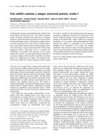
1.4. Ribbon
The ribbon is an element of the user interface which replaces the traditional menu and toolbars
and allows easy managing and customizing the workspace.
The ribbon consists of several panels, grouped on tabs that are named by task or subject. The
ribbon panels include many commands that have been on toolbars and in dialogs so far, such as
icons, drop-down lists, sliders, text fields and other elements characteristic of a given tab. Using
the ribbon, you do not have to display many toolbars; thus the application displays fewer functions
and increases the allowable workspace placing the whole interface on a small area that can be
anytime shown or hidden.
The ribbon displays automatically when a drawing is created or opened using the 2D Drafting or
3D Modeling workspace. You can display the ribbon manually using either of the following
methods:
• select the main menu Tools > Palettes > Ribbon
• type RIBBON in the command line to show the ribbon or RIBBONCLOSE to hide it.
You can customize the ribbon, that is you can add, delete and modify positions of panel elements,
in the Customize User Interface (CUI) editor window. Open this editor using either of the following
methods:
• click
on the Manage tab > Customization > User Interface
• type CUI in the command line.
NOTE:
You can display the ribbon horizontally, vertically or as a floating palette.
Using the editor you can also switch between workspaces (you can select the classic workspace
without the ribbon, for example). To do it, select the Customize tab > Workspaces and select Set
current from the context menu.
To change between workspaces, you can also use the
Workspace Switching icon at the
bottom right corner of the screen.
© 2009 Autodesk, Inc. All rights reserved